ABB RED615 Technical Manual
615 series
Hide thumbs
Also See for RED615:
- Applications manual (116 pages) ,
- Operation manual (116 pages) ,
- Product manual (73 pages)
Table of Contents
Quick Links
Chapters
Table of Contents

Related Manuals for ABB RED615


Summary of Contents for ABB RED615
- Page 1 ® Relion Protection and Control 615 series Technical Manual...
- Page 3 Document ID: 1YHT530004D05 Issued: 2014-09-12 Revision: D Product version: 4.1.1 © Copyright 2014 ABB. All rights reserved...
- Page 4 Copyright This document and parts thereof must not be reproduced or copied without written permission from ABB, and the contents thereof must not be imparted to a third party, nor used for any unauthorized purpose. The software or hardware described in this document is furnished under a license and may be used, copied, or disclosed only in accordance with the terms of such license.
- Page 5 ABB is not liable for any such damages and/or losses.
- Page 6 (EMC Directive 2004/108/EC) and concerning electrical equipment for use within specified voltage limits (Low-voltage directive 2006/95/EC). This conformity is the result of tests conducted by ABB in accordance with the product standards EN 50263 and EN 60255-26 for the EMC directive, and with the product standards EN 60255-1 and EN 60255-27 for the low voltage directive.
-
Page 7: Table Of Contents
Table of contents Table of contents Section 1 Introduction..............25 This manual..................25 Intended audience................25 Product documentation..............26 Product documentation set............26 Document revision history............26 Related documentation..............27 Symbols and conventions..............27 Symbols..................27 Document conventions..............27 Functions, codes and symbols............28 Section 2 615 series overview............33 Overview...................33 Product series version history.............33 PCM600 and IED connectivity package version......35 Local HMI..................35 Display..................36... - Page 8 Table of contents Functionality................71 Fault records..................73 Non-volatile memory.................77 Binary input..................78 Binary input filter time..............78 Binary input inversion..............79 Oscillation suppression..............79 Binary outputs...................79 Power output contacts ..............80 Dual single-pole power outputs PO1 and PO2.......80 Double-pole power outputs PO3 and PO4 with trip circuit supervision..............81 Dual single-pole high-speed power outputs HSO1, HSO2 and HSO3..............82...
- Page 9 Table of contents Function block................99 Functionality................99 Signals..................99 GOOSERCV_INT8 function block..........99 Function block................99 Functionality................99 Signals..................100 GOOSERCV_INTL function block..........100 Function block..............100 Functionality.................100 Signals..................100 GOOSERCV_CMV function block..........101 Function block..............101 Functionality.................101 Signals..................101 GOOSERCV_ENUM function block..........102 Function block..............102 Functionality.................102 Signals..................102 GOOSERCV_INT32 function block...........102 Function block..............102 Functionality.................102 Signals..................103 Type conversion function blocks............103...
- Page 10 Table of contents Settings................107 T_DIR function block..............107 Functionality.................107 Signals..................107 Configurable logic blocks..............108 Standard configurable logic blocks..........108 OR function block..............108 AND function block...............109 XOR function block...............110 NOT function block...............111 MAX3 function block.............112 MIN3 function block..............112 R_TRIG function block............113 F_TRIG function block............114 T_POS_XX function blocks..........115 SWITCHR function block............116 SR function block..............117...
- Page 11 Table of contents Settings................129 Move function block MVGAPC..........129 Function block..............129 Functionality.................129 Signals..................130 Local/remote control function block CONTROL......130 Function block..............130 Functionality.................130 Signals..................131 Settings................132 Monitored data..............133 Generic control points function block SPCGGIO.......134 Function block..............134 Functionality.................134 Signals..................135 Settings................136 Factory settings restoration............138 Section 4 Protection functions............139 Three-phase current protection............139 Three-phase non-directional overcurrent protection PHxPTOC..................139...
- Page 12 Table of contents Monitored data..............175 Technical data..............176 Three-phase directional overcurrent protection DPHxPDOC................176 Identification.................176 Function block..............177 Functionality.................177 Operation principle ..............177 Measurement modes............182 Directional overcurrent characteristics ........183 Application................191 Signals..................193 Settings................195 Monitored data..............198 Technical data..............199 Technical revision history.............200 Three-phase directional overcurrent protection DPH3xPDOC................200 Identification.................200 Function block..............201 Functionality.................201...
- Page 13 Table of contents Function block..............232 Functionality.................232 Operation principle...............233 Application................236 Signals..................238 Settings................239 Monitored data..............239 Technical data..............240 Technical revision history.............240 Motor load jam protection JAMPTOC........240 Identification.................240 Function block..............240 Functionality.................240 Operation principle...............241 Application................242 Signals..................242 Settings................243 Monitored data..............243 Technical data..............243 Loss of load supervision LOFLPTUC........244 Identification.................244 Function block..............244 Functionality.................244...
- Page 14 Table of contents Function block..............263 Functionality.................263 Operation principle...............264 Measurement modes............265 Timer characteristics............266 Application................267 Signals..................268 Settings................269 Monitored data..............271 Technical data..............272 Technical revision history.............272 Directional earth-fault protection DEFxPDEF......273 Identification.................273 Function block..............273 Functionality.................274 Operation principle...............274 Directional earth-fault principles...........279 Measurement modes............285 Timer characteristics............286 Directional earth-fault characteristics........287 Application................295 Signals..................297 Settings................298...
- Page 15 Table of contents Application................330 Signals..................334 Settings................335 Monitored data..............336 Technical data..............336 Harmonic based earth-fault protection HAEFPTOC....336 Identification.................336 Function block..............337 HAEFPTOC functionality............337 Operation principle...............337 Application................341 Signals..................342 Settings................343 Monitored data..............344 Technical data..............344 Differential protection..............345 Line differential protection and related measurements, stabilized and instantaneous stages LNPLDF......345 Identification.................345 Function block..............345 Functionality.................345...
- Page 16 Table of contents Function block..............423 Functionality.................423 Operation principle...............423 Application................427 Signals..................430 Settings................430 Monitored data..............431 Technical data..............431 High-impedance-based restricted earth-fault protection HREFPDIF.................431 Identification.................431 Function block..............432 Functionality.................432 Operation principle...............432 Application................433 The measuring configuration..........436 Recommendations for current transformers ......437 Setting examples..............441 Signals..................444 Settings................445 Monitored data..............445 Technical data..............445 Unbalance protection..............446 Negative-sequence overcurrent protection NSPTOC....446...
- Page 17 Table of contents Technical data..............456 Phase reversal protection PREVPTOC........456 Identification.................456 Function block..............457 Functionality.................457 Operation principle...............457 Application................458 Signals..................458 Settings................458 Monitored data..............459 Technical data..............459 Negative-sequence overcurrent protection for motors MNSPTOC.................459 Identification.................459 Function block..............460 Functionality.................460 Operation principle...............460 Timer characteristics............461 Application................463 Signals..................464 Settings................464 Monitored data..............465 Technical data..............465 Voltage protection................466 Three-phase overvoltage protection PHPTOV......466...
- Page 18 Table of contents Signals..................479 Settings................479 Monitored data..............480 Technical data..............481 Technical revision history.............481 Residual overvoltage protection ROVPTOV......481 Identification.................481 Function block..............481 Functionality.................482 Operation principle...............482 Application................483 Signals..................483 Settings................484 Monitored data..............484 Technical data..............484 Technical revision history.............485 Negative-sequence overvoltage protection NSPTOV....485 Identification.................485 Function block..............485 Functionality.................485 Operation principle...............486 Application................487 Signals..................487...
- Page 19 Table of contents Operation principle...............494 Application................500 Signals..................501 Settings................501 Monitored data..............502 Technical data..............502 Load shedding and restoration LSHDPFRQ......502 Identification.................502 Function block..............503 Functionality.................503 Operation principle...............503 Application................508 Signals..................512 Settings................512 Monitored data..............513 Technical data..............513 Arc protection ARCSARC...............514 Identification................514 Function block................514 Functionality................514 Operation principle..............514 Application.................516 Signals..................519 Settings..................520 Monitored data................520...
- Page 20 Table of contents Settings..................535 Monitored data................536 Technical data................536 Section 5 Protection related functions..........537 Three-phase inrush detector INRPHAR.........537 Identification................537 Function block................537 Functionality................537 Operation principle..............537 Application.................539 Signals..................540 Settings..................540 Monitored data................541 Technical data................541 Circuit breaker failure protection CCBRBRF........541 Identification................541 Function block................541 Functionality................542 Operation principle..............542 Application.................548 Signals..................550 Settings..................550...
- Page 21 Table of contents Technical data................560 Emergency startup ESMGAPC............560 Identification................560 Function block................561 Functionality................561 Operation principle..............561 Application.................562 Signals..................562 Settings..................563 Monitored data................563 Technical data................563 Switch on to fault control CBRSOF..........563 Identification................563 Function block................564 Functionality................564 Principle of operation..............564 Application.................565 Signals..................565 Settings..................566 Monitored data................566 Uncorresponding position startup UPSCBR........566 Identification................566 Function block................566 Functionality................567...
- Page 22 Table of contents Operation principle..............581 Application.................583 Signals..................587 Settings..................588 Monitored data................588 Technical data................588 Protection communication supervision PCSRTPC......588 Identification................588 Function block................589 Functionality................589 Operation principle..............590 Application.................591 Signals..................592 Settings..................592 Monitored data................592 Technical revision history............593 Fuse failure supervision SEQRFUF..........593 Identification................593 Function block................593 Functionality................593 Operation principle..............594 Application.................597 Signals..................598 Settings..................598...
- Page 23 Table of contents Settings..................605 Technical data................605 Section 7 Condition monitoring functions........607 Circuit breaker condition monitoring SSCBR........607 Identification................607 Function block................607 Functionality................607 Operation principle..............608 Circuit breaker status............609 Circuit breaker operation monitoring........609 Breaker contact travel time...........610 Operation counter..............611 Accumulation of I t..............612 Remaining life of circuit breaker...........613 Circuit breaker spring-charged indication......615 Gas pressure supervision.............615 Application.................616...
- Page 24 Table of contents Residual current measurement RESCMMXU......638 Identification.................638 Function block..............638 Signals..................638 Settings................638 Monitored data..............639 Technical data..............639 Technical revision history.............639 Residual voltage measurement RESVMMXU......639 Identification.................639 Function block..............640 Signals..................640 Settings................640 Monitored data..............640 Technical data..............641 Technical revision history.............641 Frequency measurement FMMXU..........641 Identification.................641 Function block..............641 Signals..................641 Settings................642 Monitored data..............642...
- Page 25 Table of contents Monitored data..............648 Technical data..............649 Disturbance recorder..............649 Functionality................649 Recorded analog inputs............650 Triggering alternatives............650 Length of recordings.............651 Sampling frequencies............652 Uploading of recordings............652 Deletion of recordings............653 Storage mode...............653 Pre-trigger and post-trigger data..........654 Operation modes..............654 Exclusion mode..............655 Configuration................655 Application.................656 Settings..................657 Monitored data................660 Technical revision history............660 Tap changer position indicator TPOSSLTC........660 Identification................660...
- Page 26 Table of contents Disconnector position indicator DCSXSWI and earthing switch indication ESSXSWI...............676 Identification................676 Function block................676 Functionality................677 Operation principle..............677 Application.................677 Signals..................677 Settings..................678 Monitored data................678 Synchronism and energizing check SECRSYN......679 Identification................679 Function block................679 Functionality................679 Operation principle..............680 Application.................687 Signals..................689 Settings..................690 Monitored data................691 Technical data................691 Autoreclosing DARREC..............692 Identification................692 Function block................692...
- Page 27 Table of contents Fast trip in Switch on to fault..........720 Signals..................721 Settings..................722 Monitored data................724 Technical data................725 Technical revision history............726 Tap changer control with voltage regulator OLATCC.....726 Identification................726 Function block................726 Functionality................726 Operation principle..............727 Voltage and current measurements..........728 Tap changer position inputs............729 Operation mode selection............730 Manual voltage regulation............731 Automatic voltage regulation of single transformer....732...
- Page 28 Table of contents Functionality................769 Operation principle..............769 Application.................770 Signals..................770 Settings..................771 Monitored data................771 Voltage variation PHQVVR.............772 Identification................772 Function block................772 Functionality................772 Operation principle..............773 Phase mode setting..............773 Variation detection..............774 Variation validation...............775 Duration measurement............778 Three/single-phase selection variation examples....779 Recorded data................781 Application.................783 Signals..................785 Settings..................786 Monitored data................787 Section 11 General function block features........791 Definite time characteristics............791 Definite time operation...............791...
- Page 29 Table of contents IDMT curve saturation of undervoltage protection....838 Frequency measurement and protection........838 Measurement modes..............839 Calculated measurements..............841 Section 12 Requirements for measurement transformers....843 Current transformers..............843 Current transformer requirements for non-directional overcurrent protection..............843 Current transformer accuracy class and accuracy limit factor..................843 Non-directional overcurrent protection.........844 Example for non-directional overcurrent protection....845 Section 13 IED physical connections..........847...
-
Page 31: Section 1 Introduction
Section 1 1YHT530004D05 D Introduction Section 1 Introduction This manual The technical manual contains application and functionality descriptions and lists function blocks, logic diagrams, input and output signals, setting parameters and technical data sorted per function. The manual can be used as a technical reference during the engineering phase, installation and commissioning phase, and during normal service. -
Page 32: Product Documentation
A/2009-09-29 First release B/2010-07-02 Content updated C/2014-05-14 Content updated to correspond to the product series version D/2014-09-12 4.1.1 Content updated to correspond to the product series version Download the latest documents from the ABB Website http://www.abb.com/substationautomation. 615 series Technical Manual... -
Page 33: Related Documentation
Section 1 1YHT530004D05 D Introduction 1.3.3 Related documentation Product series- and product-specific manuals can be downloaded from the ABB Website http://www.abb.com/substationautomation. Symbols and conventions 1.4.1 Symbols The electrical warning icon indicates the presence of a hazard which could result in electrical shock. -
Page 34: Functions, Codes And Symbols
Section 1 1YHT530004D05 D Introduction To navigate between the options, use • HMI menu paths are presented in bold. Select Main menu/Settings. • LHMI messages are shown in Courier font. To save the changes in non-volatile memory, select Yes and press •... - Page 35 Section 1 1YHT530004D05 D Introduction Function IEC 61850 IEC 60617 IEC-ANSI Three-phase directional overcurrent protection that contains three independent phase-segregated timers, DPH3LPDOC2 3I> -> (2) 67-1 (2) low stage, instance 2 Three-phase directional overcurrent protection that contains three independent phase-segregated timers, DPH3HPDOC1 3I>>...
- Page 36 Section 1 1YHT530004D05 D Introduction Function IEC 61850 IEC 60617 IEC-ANSI Negative-sequence overcurrent protection for motors, MNSPTOC1 I2>M (1) 46M (1) instance 1 Negative-sequence overcurrent protection for motors, MNSPTOC2 I2>M (2) 46M (2) instance 2 Loss of load supervision LOFLPTUC1 3I<...
- Page 37 Section 1 1YHT530004D05 D Introduction Function IEC 61850 IEC 60617 IEC-ANSI Tap changer control with voltage regulator OLATCC1 COLTC Synchronism and energizing check SECRSYN1 SYNC Condition monitoring Circuit-breaker condition monitoring SSCBR1 CBCM CBCM Trip circuit supervision, instance 1 TCSSCBR1 TCS (1) TCM (1) Trip circuit supervision, instance 2 TCSSCBR2...
-
Page 39: Section 2 615 Series Overview
RET615 with configurations A, B, C, D, J and K • REM615 with configuration C New configurations: • REF615: E, F and J • RED615: B and C Platform enhancements: • Support for IEC 60870-5-103 • Voltage measurement and protection •... - Page 40 • REF615 A, B, E, F and J • RET615 A, B, C, D, J and K • REM615 C • RED615 B Platform enhancements: • Application configurability support • Analog GOOSE support • Large display with single line diagram •...
-
Page 41: Pcm600 And Ied Connectivity Package Version
PCM600 and IED connectivity package version • Protection and Control IED Manager PCM600 Ver. 2.6 or later • RED615 Connectivity Package Ver. 4.1 or later • REF615 Connectivity Package Ver. 4.1 or later • REM615 Connectivity Package Ver. 4.1 or later •... -
Page 42: Display
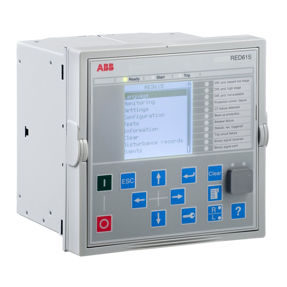
Section 2 1YHT530004D05 D 615 series overview REF615 Overcurrent Dir. earth-fault Voltage protection Phase unbalance Thermal overload Breaker failure Disturb. rec. Triggered CB condition monitoring Supervision Arc detected Autoreclose shot in progr. A070704 V3 EN Figure 2: Example of the LHMI 2.2.1 Display The LHMI includes a graphical display that supports two character sizes. -
Page 43: Leds
Section 2 1YHT530004D05 D 615 series overview The display view is divided into four basic areas. A070705 V3 EN Figure 3: Display layout 1 Header 2 Icon 3 Content 4 Scroll bar (displayed when needed) 2.2.2 LEDs The LHMI includes three protection indicators above the display: Ready, Start and Trip. -
Page 44: Web Hmi
Section 2 1YHT530004D05 D 615 series overview A071176 V1 EN Figure 4: LHMI keypad with object control, navigation and command push- buttons and RJ-45 communication port Web HMI The WHMI allows accessing the IED via a Web browser. The supported Web browser versions are Internet Explorer 7.0, 8.0 and 9.0. -
Page 45: Authorization
Section 2 1YHT530004D05 D 615 series overview A070754 V4 EN Figure 5: Example view of the WHMI The WHMI can be accessed locally and remotely. • Locally by connecting the laptop to the IED via the front communication port. • Remotely over LAN/WAN. -
Page 46: Audit Trail
Section 2 1YHT530004D05 D 615 series overview Table 4: Predefined user categories Username User rights VIEWER Read only access OPERATOR • Selecting remote or local state with (only locally) • Changing setting groups • Controlling • Clearing indications ENGINEER • Changing settings •... - Page 47 Section 2 1YHT530004D05 D 615 series overview Audit trail event Description Setting group local User changed setting group locally Control remote DPC object control remote Control local DPC object control local Test on Test mode on Test off Test mode off Setting commit Settings have been changed Time change...
-
Page 48: Communication
Section 2 1YHT530004D05 D 615 series overview Audit trail event Authority logging level Logout ● Firmware reset ● Audit overflow ● Communication The IED supports a range of communication protocols including IEC 61850, IEC ® 60870-5-103 and Modbus . Operational information and controls are available through these protocols. - Page 49 Section 2 1YHT530004D05 D 615 series overview Client A Client B Network A Network B Managed Ethernet switch Managed Ethernet switch with RSTP support with RSTP support GUID-283597AF-9F38-4FC7-B87A-73BFDA272D0F V3 EN Figure 6: Self-healing Ethernet ring solution The Ethernet ring solution supports the connection of up to 30 IEDs.
-
Page 51: Section 3 Basic Functions
Section 3 1YHT530004D05 D Basic functions Section 3 Basic functions General parameters Table 7: Analog input settings, phase currents Parameter Values (Range) Unit Step Default Description Secondary current 2=1A 2=1A Rated secondary current 3=5A Primary current 1.0...6000.0 100.0 Rated primary current Amplitude corr. - Page 52 Section 3 1YHT530004D05 D Basic functions Parameter Values (Range) Unit Step Default Description Amplitude corr. B 0.900...1.100 0.001 1.000 Phase B Voltage phasor magnitude correction of an external voltage transformer Amplitude corr. C 0.900...1.100 0.001 1.000 Phase C Voltage phasor magnitude correction of an external voltage transformer Division ratio...
- Page 53 Section 3 1YHT530004D05 D Basic functions Table 13: Ethernet front port settings Parameter Values (Range) Unit Step Default Description IP address 192.168.0.254 IP address for front port (fixed) Mac address XX-XX-XX-XX- Mac address for front port XX-XX Table 14: Ethernet rear port settings Parameter Values (Range) Unit...
- Page 54 Section 3 1YHT530004D05 D Basic functions Table 18: General system settings Parameter Values (Range) Unit Step Default Description Rated frequency 1=50Hz 1=50Hz Rated frequency of the network Phase rotation 1=ABC 1=ABC Phase rotation order 2=ACB Blocking mode 1=Freeze timer 1=Freeze timer Behaviour for function BLOCK inputs 2=Block all 3=Block OPERATE...
- Page 55 Section 3 1YHT530004D05 D Basic functions Parameter Values (Range) Unit Step Default Description Class1Priority 1 0=Ev High 0=Ev High Class 1 data sending priority relationship 1=Ev/DR Equal between Events and Disturbance 2=DR High Recorder data. Frame1InUse 1 -1=Not in use 6=Private frame 6 Active Class2 Frame 1 for instance 1 0=User frame...
- Page 56 Section 3 1YHT530004D05 D Basic functions Parameter Values (Range) Unit Step Default Description Class1OvInd 1 0=No indication 2=Rising edge Overflow Indication for instance 1 1=Both edges 2=Rising edge Class1OvFType 1 0...255 Function Type for Class 1 overflow indication for instance 1 Class1OvInfNo 1 0...255 Information Number for Class 1 overflow...
- Page 57 Section 3 1YHT530004D05 D Basic functions Parameter Values (Range) Unit Step Default Description Frame2InUse 2 -1=Not in use -1=Not in use Active Class2 Frame 2 for instance 2 0=User frame 1=Standard frame 2=Standard frame 3=Standard frame 4=Standard frame 5=Standard frame 6=Private frame 6 7=Private frame 7 Frame3InUse 2...
- Page 58 Section 3 1YHT530004D05 D Basic functions Table 21: IEC 61850-8-1 MMS settings Parameter Values (Range) Unit Step Default Description Unit mode 1=Primary 0=Nominal IEC 61850-8-1 unit mode 0=Nominal 2=Primary-Nominal Table 22: Modbus settings Parameter Values (Range) Unit Step Default Description Serial port 1 0=Not in use 0=Not in use...
- Page 59 Section 3 1YHT530004D05 D Basic functions Parameter Values (Range) Unit Step Default Description CtlStructPWd1 **** Password for Modbus control struct 1 CtlStructPWd2 **** Password for Modbus control struct 2 CtlStructPWd3 **** Password for Modbus control struct 3 CtlStructPWd4 **** Password for Modbus control struct 4 CtlStructPWd5 **** Password for Modbus control struct 5...
- Page 60 Section 3 1YHT530004D05 D Basic functions Table 24: Serial communication settings Parameter Values (Range) Unit Step Default Description Fiber mode 0=No fiber 0=No fiber Fiber mode for COM2 2=Fiber optic Serial mode 1=RS485 2Wire 1=RS485 2Wire Serial mode for COM2 2=RS485 4Wire 3=RS232 no handshake...
- Page 61 Section 3 1YHT530004D05 D Basic functions Parameter Values (Range) Unit Step Default Description DST on day 0=Not in use 0=Not in use Daylight savings time on, day of week 1=Mon 2=Tue 3=Wed 4=Thu 5=Fri 6=Sat 7=Sun DST offset -720...720 Daylight savings time offset, in minutes DST off time 02:00 Daylight savings time off, time (hh:mm)
- Page 62 Section 3 1YHT530004D05 D Basic functions Table 28: X110 BIO binary input signals Name Type Description X110-Input 1 BOOLEAN Connectors 1-2 X110-Input 2 BOOLEAN Connectors 3-4 X110-Input 3 BOOLEAN Connectors 5-6c X110-Input 4 BOOLEAN Connectors 7-6c X110-Input 5 BOOLEAN Connectors 8-9c X110-Input 6 BOOLEAN Connectors 10-9c...
- Page 63 Section 3 1YHT530004D05 D Basic functions Table 30: X120 AIM binary input signals Name Type Description X120-Input 1 BOOLEAN Connectors 1-2c X120-Input 2 BOOLEAN Connectors 3-2c X120-Input 3 BOOLEAN Connectors 4-2c X120-Input 4 BOOLEAN Connectors 5-6 Table 31: X120 AIM binary input settings Parameter Values (Range) Unit...
- Page 64 Section 3 1YHT530004D05 D Basic functions Table 34: X130 BIO binary input settings Parameter Values (Range) Unit Step Default Description Input 1 filter time 5...1000 Connectors 1-2c Input 2 filter time 5...1000 Connectors 3-2c Input 3 filter time 5...1000 Connectors 4-5c Input 4 filter time 5...1000 Connectors 6-5c...
-
Page 65: Self-Supervision
Section 3 1YHT530004D05 D Basic functions Self-supervision The IED's extensive self-supervision system continuously supervises the software and the electronics. It handles run-time fault situation and informs the user about a fault via the LHMI and through the communications channels. There are two types of fault indications. •... - Page 66 Figure 7: Output contact The internal fault code indicates the type of internal IED fault. When a fault appears, the code must be recorded so that it can be reported to ABB customer service. Table 37: Internal fault indications and codes...
-
Page 67: Warnings
Section 3 1YHT530004D05 D Basic functions Fault indication Fault code Additional information Internal Fault Card in slot X110 is wrong type, is Conf. error,X110 missing or does not belong to the original composition. Internal Fault Card in slot X120 is wrong type, is Conf. - Page 68 Section 3 1YHT530004D05 D Basic functions If a warning appears, record the name and code so that it can be provided to ABB customer service. Table 38: Warning indications and codes Warning indication Warning code Additional information Warning A watchdog reset has occurred.
-
Page 69: Led Indication Control
Section 3 1YHT530004D05 D Basic functions For further information on warning indications, see the operation manual. LED indication control The IED includes a global conditioning function LEDPTRC that is used with the protection indication LEDs. LED indication control should never be used for tripping purposes. There is a separate trip logic function TRPPTRC available in the IED configuration. - Page 70 Section 3 1YHT530004D05 D Basic functions REF615 Overcurrent Dir. earth-fault Voltage protection Phase unbalance Thermal overload Breaker failure Disturb. rec. Triggered CB condition monitoring Supervision Arc detected Autoreclose shot in progr. A070704 V3 EN Figure 9: Programmable LEDs on the right side of the display All the programmable LEDs in the HMI of the IED have two colors, green and red.
- Page 71 Section 3 1YHT530004D05 D Basic functions The LED status also provides a means for resetting the individual LED via communication. The LED can also be reset from configuration with the RESET input. The resetting and clearing function for all LEDs is under the Clear menu. The menu structure for the programmable LEDs is presented in Figure 10.
-
Page 72: Signals
Section 3 1YHT530004D05 D Basic functions "Latched-S": Latched, ON This mode is a latched function. At the activation of the input signal, the alarm shows a steady light. After acknowledgement, the alarm disappears. Activating signal Acknow. GUID-055146B3-780B-43E6-9E06-9FD8D342E881 V1 EN Figure 13: Operating sequence "Latched-S"... -
Page 73: Settings
Section 3 1YHT530004D05 D Basic functions Name Type Default Description RESET BOOLEAN 0=False Reset input for LED 3 BOOLEAN 0=False Ok input for LED 4 ALARM BOOLEAN 0=False Alarm input for LED 4 RESET BOOLEAN 0=False Reset input for LED 4 BOOLEAN 0=False Ok input for LED 5... - Page 74 Section 3 1YHT530004D05 D Basic functions Parameter Values (Range) Unit Step Default Description Description Programmable Programmable LED description LEDs LED 2 Alarm mode 0=Follow-S 0=Follow-S Alarm mode for programmable LED 3 1=Follow-F 2=Latched-S 3=LatchedAck-F-S Description Programmable Programmable LED description LEDs LED 3 Alarm mode 0=Follow-S 0=Follow-S...
-
Page 75: Monitored Data
Section 3 1YHT530004D05 D Basic functions Parameter Values (Range) Unit Step Default Description Description Programmable Programmable LED description LEDs LED 10 Alarm mode 0=Follow-S 0=Follow-S Alarm mode for programmable LED 11 1=Follow-F 2=Latched-S 3=LatchedAck-F-S Description Programmable Programmable LED description LEDs LED 11 3.4.5 Monitored data Table 41:... -
Page 76: Time Synchronization
Section 3 1YHT530004D05 D Basic functions Time synchronization The IED has an internal real-time clock which can be either free-running or synchronized from an external source. The real-time clock is used for time stamping events, recorded data and disturbance recordings. The IED is provided with a 48-hour capacitor back-up that enables the real-time clock to keep time in case of an auxiliary power failure. -
Page 77: Parameter Setting Groups
IRIG-B time synchronization requires a COM card with an IRIG-B input. When using line differential communication between RED615 IEDs, the time synchronization messages can be received from the other line end IED within the protection telegrams. The IED begins to synchronize its real-time clock with the remote end IEDs time if the Line differential time synchronization source is selected. - Page 78 Section 3 1YHT530004D05 D Basic functions The default value of all inputs is FALSE, which makes it possible to use only the required number of inputs and leave the rest disconnected. The setting group selection is not dependent on the SG_x_ACT outputs. Table 42: Optional operation modes for setting group selection SG operation mode...
-
Page 79: Fault Records
Section 3 1YHT530004D05 D Basic functions The setting group 1 can be copied to any other or all groups from HMI (Copy group 1). Fault records The IED has the capacity to store the records of 128 latest fault events. Fault records include fundamental or RMS current values. - Page 80 Section 3 1YHT530004D05 D Basic functions Table 45: FLTMSTA Non group settings Parameter Values (Range) Unit Step Default Description Operation 1=on 1=on Operation Off / On 5=off Trig mode 0=From all faults 0=From all faults Triggering mode 1=From operate 2=From only start A measurement mode 1=RMS 2=DFT...
- Page 81 Section 3 1YHT530004D05 D Basic functions Name Type Values (Range) Unit Description Bias current Io FLOAT32 0.000...50.000 Bias current residual Max current IL1 FLOAT32 0.000...50.000 Maximum phase A current Max current IL2 FLOAT32 0.000...50.000 Maximum phase B current Max current IL3 FLOAT32 0.000...50.000 Maximum phase C...
- Page 82 Section 3 1YHT530004D05 D Basic functions Name Type Values (Range) Unit Description Current IL2C FLOAT32 0.000...50.000 Phase B current (c) Current IL3C FLOAT32 0.000...50.000 Phase C current (c) Current IoC FLOAT32 0.000...50.000 Residual current (c) Current Io-CalcC FLOAT32 0.000...50.000 Calculated residual current (c) Current Ps-SeqC FLOAT32...
-
Page 83: Non-Volatile Memory
Section 3 1YHT530004D05 D Basic functions Name Type Values (Range) Unit Description Frequency FLOAT32 30.00...80.00 Frequency Frequency gradient FLOAT32 -10.00...10.00 Hz/s Frequency gradient Conductance Yo FLOAT32 -1000.00...1000. Conductance Yo Susceptance Yo FLOAT32 -1000.00...1000. Susceptance Yo Angle Uo - Io FLOAT32 -180.00...180.00 Angle residual voltage - residual current... -
Page 84: Binary Input
Section 3 1YHT530004D05 D Basic functions Binary input 3.9.1 Binary input filter time The filter time eliminates debounces and short disturbances on a binary input. The filter time is set for each binary input of the IED. GUID-13DA5833-D263-4E23-B666-CF38B1011A4B V1 EN Figure 16: Binary input filtering 3 Input signal... -
Page 85: Binary Input Inversion
Section 3 1YHT530004D05 D Basic functions 3.9.2 Binary input inversion The parameter Input # invert is used to invert a binary input. Table 48: Binary input states Control voltage Input # invert State of binary input False (0) True (1) True (0) False (0) When a binary input is inverted, the state of the input is TRUE (1) when no control... -
Page 86: Power Output Contacts
Section 3 1YHT530004D05 D Basic functions Power output contacts are used when the current rating requirements of the contacts are high, for example, for controlling a breaker, such as energizing the breaker trip and closing coils. The contacts used for external signalling, recording and indicating, the signal outputs, need to adjust to smaller currents, but they can require a minimum current (burden) to ensure a guaranteed operation. -
Page 87: Double-Pole Power Outputs Po3 And Po4 With Trip Circuit Supervision
Section 3 1YHT530004D05 D Basic functions X100 GUID-4E1E21B1-BEEC-4351-A7BE-9D2DBA451985 V1 EN Figure 17: Dual single-pole power output contacts PO1 and PO2 3.10.1.2 Double-pole power outputs PO3 and PO4 with trip circuit supervision The power outputs PO3 and PO4 are double-pole normally open/form A power outputs with trip circuit supervision. -
Page 88: Dual Single-Pole High-Speed Power Outputs Hso1, Hso2 And Hso3
Section 3 1YHT530004D05 D Basic functions X100 TCS1 TCS2 GUID-5A0502F7-BDC4-424A-BF19-898025FCCBD7 V1 EN Figure 18: Double-pole power outputs PO3 and PO4 with trip circuit supervision Power outputs PO3 and PO4 are included in the power supply module located in slot X100 of the IED. 3.10.1.3 Dual single-pole high-speed power outputs HSO1, HSO2 and HSO3 HSO1, HSO2 and HSO3 are dual parallel connected, single-pole, normally open/... -
Page 89: Signal Output Contacts
Section 3 1YHT530004D05 D Basic functions X110 HSO1 HSO2 HSO3 GUID-38EDD366-7456-4933-B49E-0F43FE1D6C39 V1 EN Figure 19: High-speed power outputs HSO1, HSO2 and HSO3 The reset time of the high-speed output contacts is longer than that of the conventional output contacts. High-speed power contacts are part of the card BIO0007 with eight binary inputs and three HSOs. -
Page 90: Signal Outputs So1 And So2 In Power Supply Module
Section 3 1YHT530004D05 D Basic functions X100 GUID-C09595E9-3C42-437A-BDB2-B20C35FA0BD2 V1 EN Figure 20: Internal fault signal output IRF 3.10.2.2 Signal outputs SO1 and SO2 in power supply module Signal outputs (normally open/form A or change-over/form C) SO1 (dual parallel form C) and SO2 (single contact/form A) are part of the power supply module of the IED. -
Page 91: Signal Outputs So1, So2 And So3 In Bio0006
Section 3 1YHT530004D05 D Basic functions X110 X110 GUID-CBA9A48A-2549-455B-907D-8261E2259BF4 V1 EN Figure 22: Signal output in BIO0005 3.10.2.4 Signal outputs SO1, SO2 and SO3 in BIO0006 The optional card BIO0006 provides the signal outputs SO1, SO2 and SO3. Signal outputs SO1 and SO2 are dual, parallel form C contacts; SO3 is a single form C contact. -
Page 92: Rtd/Ma Inputs
Section 3 1YHT530004D05 D Basic functions X130 GUID-C5B5FD1C-617B-4F38-A0D4-D98735E69530 V1 EN Figure 23: Signal output in BIO0006 3.11 RTD/mA inputs 3.11.1 Functionality RTD and mA analog input module is used for monitoring and metering milli- ampere (mA), temperature (°C) and resistance (Ω). Each input can be linearly scaled for various applications, for example, transformer’s tap changer position indication. -
Page 93: Selection Of Output Value Format
Section 3 1YHT530004D05 D Basic functions Table 50: Limits for the RTD/mA inputs Input mode Description Not in use Default selection. Used when the corresponding input is not used. 0...20 mA Selection for analog DC milli-ampere current inputs in the input range of 0 – 20 mA. Resistance Selection for RTD inputs in the input range of 0 –... -
Page 94: Measurement Chain Supervision
Section 3 1YHT530004D05 D Basic functions The input scaling can be bypassed by selecting Value unit = "Ohm" when Input mode = "Resistance" is used and by selecting Value unit = "Ampere" when Input mode = "0...20 mA" is used. Example for linear scaling Milli-ampere input is used as tap changer position information. -
Page 95: Calibration
Section 3 1YHT530004D05 D Basic functions sensor type. If the measured offset current deviates from the reference current more than 20%, the sample is discarded and the output is set to invalid. The invalid measure status deactivates as soon as the measured input signal is within the measurement offset. -
Page 96: Deadband Supervision
Section 3 1YHT530004D05 D Basic functions Table 52: Settings for X130 (RTD) analog input limit value supervision Function Settings for limit value supervision X130 (RTD) analog input Out of range Value maximum High-high limit Val high high limit High limit Val high limit Low limit Val low limit... -
Page 97: Rtd Temperature Vs. Resistance
Section 3 1YHT530004D05 D Basic functions Example of X130 (RTD) analog input deadband supervision Temperature sensor Pt100 is used in the temperature range of 15...180 °C. Value unit “Degrees Celsius” is used and the set values Value minimum and Value maximum are set to 15 and 180, respectively. -
Page 98: Rtd/Ma Input Connection
Section 3 1YHT530004D05 D Basic functions Temp Platinum TCR 0.00385 Nickel TCR 0.00618 Copper TCR °C 0.00427 Pt 100 Pt 250 Ni 100 Ni 120 Ni 250 Cu 10 130.89 327.225 148.3 177.96 370.75 12.124 134.7 336.75 154.9 185.88 387.25 138.5 346.25 161.8... - Page 99 Section 3 1YHT530004D05 D Basic functions GUID-2702C0B0-99CF-40D0-925C-BEC0725C0E97 V1 EN Figure 28: Three RTD/resistance sensors connected according to the 2-wire connection X130 Sensor Shunt Transducer (44 Ω) GUID-88E6BD08-06B8-4ED3-B937-4CC549697684 V1 EN Figure 29: mA wiring connection 615 series Technical Manual...
-
Page 100: Signals
Section 3 1YHT530004D05 D Basic functions 3.11.3 Signals Table 55: X130 (RTD/mA) analog input signals Name Type Description ALARM BOOLEAN General alarm WARNING BOOLEAN General warning AI_VAL1 FLOAT32 mA input, Connectors 1-2, instantaneous value AI_VAL2 FLOAT32 mA input, Connectors 3-4, instantaneous value AI_VAL3 FLOAT32 RTD input, Connectors 5-6-11c, instantaneous... - Page 101 Section 3 1YHT530004D05 D Basic functions Parameter Values (Range) Unit Step Default Description Value high limit -10000.0...10000.0 10000.0 Output value high warning limit for supervision Value low limit -10000.0...10000.0 -10000.0 Output value low warning limit for supervision Value low low limit -10000.0...10000.0 -10000.0 Output value low alarm limit for...
- Page 102 Section 3 1YHT530004D05 D Basic functions Table 58: X130 (RTD/mA) monitored data Name Type Values (Range) Unit Description AI_DB1 FLOAT32 -10000.0...10000 mA input, Connectors 1-2, reported value AI_RANGE1 Enum 0=normal mA input, Connectors 1=high 1-2, range 2=low 3=high-high 4=low-low AI_DB2 FLOAT32 -10000.0...10000 mA input, Connectors...
-
Page 103: Goose Function Blocks
Section 3 1YHT530004D05 D Basic functions Name Type Values (Range) Unit Description AI_RANGE7 Enum 0=normal RTD input, Connectors 1=high 15-16-12c, range 2=low 3=high-high 4=low-low AI_DB8 FLOAT32 -10000.0...10000 RTD input, Connectors 17-18-12c, reported value AI_RANGE8 Enum 0=normal RTD input, Connectors 1=high 17-18-12c, range 2=low 3=high-high... -
Page 104: Functionality
Section 3 1YHT530004D05 D Basic functions 3.12.1.2 Functionality The GOOSERCV_BIN function is used to connect the GOOSE binary inputs to the application. 3.12.1.3 Signals Table 59: GOOSERCV_BIN Input signals Name Type Default Description BOOLEAN Input signal Table 60: GOOSERCV_BIN Output signals Name Type Description... -
Page 105: Goosercv_Mv Function Block
Section 3 1YHT530004D05 D Basic functions 3.12.3 GOOSERCV_MV function block 3.12.3.1 Function block GUID-A59BAF25-B9F8-46EA-9831-477AC665D0F7 V1 EN Figure 32: Function block 3.12.3.2 Functionality The GOOSERCV_MV function is used to connect the GOOSE measured value inputs to the application. 3.12.3.3 Signals Table 63: GOOSERCV_MV Input signals Name Type... -
Page 106: Signals
Section 3 1YHT530004D05 D Basic functions 3.12.4.3 Signals Table 65: GOOSERCV_INT8 Input signals Name Type Description INT8 Input signal Table 66: GOOSERCV_INT8 Output signals Name Type Description INT8 Output signal VALID BOOLEAN Output signal 3.12.5 GOOSERCV_INTL function block 3.12.5.1 Function block GUID-241A36E0-1BB9-4323-989F-39668A7B1DAC V1 EN Figure 34: Function block... -
Page 107: Goosercv_Cmv Function Block
Section 3 1YHT530004D05 D Basic functions Table 68: GOOSERCV_INTL Output signals Name Type Description BOOLEAN Position open output signal BOOLEAN Position closed output signal BOOLEAN Position OK output signal VALID BOOLEAN Output signal 3.12.6 GOOSERCV_CMV function block 3.12.6.1 Function block GUID-4C3F3A1A-F5D1-42E1-840F-6106C58CB380 V1 EN Figure 35: Function block... -
Page 108: Goosercv_Enum Function Block
Section 3 1YHT530004D05 D Basic functions 3.12.7 GOOSERCV_ENUM function block 3.12.7.1 Function block GUID-E1AE8AD3-ED99-448A-8C11-558BCA68CDC4 V1 EN Figure 36: Function block 3.12.7.2 Functionality The GOOSERCV_ENUM function block is used to connect GOOSE enumerator inputs to the application. 3.12.7.3 Signals Table 71: GOOSERCV_ENUM Input signals Name Type... -
Page 109: Signals
Section 3 1YHT530004D05 D Basic functions 3.12.8.3 Signals Table 73: GOOSERCV_INT32 Input signals Name Type Default Description INT32 Input signal Table 74: GOOSERCV_INT32 Output signals Name Type Description INT32 Output signal VALID BOOLEAN Output signal 3.13 Type conversion function blocks 3.13.1 QTY_GOOD function block 3.13.1.1... -
Page 110: Qty_Bad Function Block
Section 3 1YHT530004D05 D Basic functions Table 76: QTY_GOOD Output signals Name Type Description BOOLEAN Output signal 3.13.2 QTY_BAD function block 3.13.2.1 Fucntion block GUID-8C120145-91B6-4295-98FB-AE78430EB532 V1 EN Figure 39: Function block 3.13.2.2 Functionality The QTY_BAD function block evaluates the quality bits of the input signal and passes it as a Boolean signal for the application. -
Page 111: Qty_Goose_Comm Function Block
Section 3 1YHT530004D05 D Basic functions 3.13.3 QTY_GOOSE_COMM function block 3.13.3.1 Functionality The QTY_GOOSE_COMM function block evaluates the peer IED communication status from the quality bits of the input signal and passes it as a Boolean signal to the application. The IN input can be connected to any GOOSE application logic output signal, for example, GOOSERCV_BIN. -
Page 112: Signals
Section 3 1YHT530004D05 D Basic functions The outputs OK, WARNING and ALARM are extracted from the enumerated input value. Only one of the outputs can be active at a time. In case the GOOSERCV_ENUM function block doesn't receive the value from the sending IED, the default value (0) is used and the ALARM is activated in the T_HEALTH function block. -
Page 113: Settings
Section 3 1YHT530004D05 D Basic functions Table 84: T_F32_INT8 Output signal Name Type Description INT8 INT8 Output signal 3.13.5.4 Settings The function does not have any parameters available in LHMI or Protection and Control IED Manager (PCM600). 3.13.6 T_DIR function block 3.13.6.1 Functionality The T_DIR function evaluates enumerated data of the FAULT_DIR data attribute... -
Page 114: Configurable Logic Blocks
Section 3 1YHT530004D05 D Basic functions 3.14 Configurable logic blocks 3.14.1 Standard configurable logic blocks 3.14.1.1 OR function block Function block GUID-9D001113-8912-440D-B206-051DED17A23C V1 EN Figure 42: Function blocks Functionality OR and OR6 are used to form general combinatory expressions with Boolean variables. -
Page 115: And Function Block
Section 3 1YHT530004D05 D Basic functions Table 89: OR Output signal Name Type Description BOOLEAN Output signal Table 90: OR6 Output signal Name Type Description BOOLEAN Output signal Settings The function does not have any parameters available in LHMI or Protection and Control IED Manager (PCM600). -
Page 116: Xor Function Block
Section 3 1YHT530004D05 D Basic functions Table 92: AND6 Input signals Name Type Default Description BOOLEAN Input signal 1 BOOLEAN Input signal 2 BOOLEAN Input signal 3 BOOLEAN Input signal 4 BOOLEAN Input signal 5 BOOLEAN Input signal 6 Table 93: AND Output signal Name Type... -
Page 117: Not Function Block
Section 3 1YHT530004D05 D Basic functions Signals Table 95: XOR Input signals Name Type Default Description BOOLEAN Input signal 1 BOOLEAN Input signal 2 Table 96: XOR Output signal Name Type Description BOOLEAN Output signal Settings The function does not have any parameters available in LHMI or Protection and Control IED Manager (PCM600). -
Page 118: Max3 Function Block
Section 3 1YHT530004D05 D Basic functions 3.14.1.5 MAX3 function block Function block GUID-5454FE1C-2947-4337-AD58-39D266E91993 V1 EN Figure 46: Function block Functionality The maximum function MAX3 selects the maximum value from three analog values. The disconnected inputs have the value 0. Signals Table 99: MAX3 Input signals Name... -
Page 119: R_Trig Function Block
Section 3 1YHT530004D05 D Basic functions If the minimum value is to be selected from two signals, connecting one of the inputs to two in MIN3 makes all the inputs to be connected. Signals Table 101: MIN3 Input signals Name Type Default Description... -
Page 120: F_Trig Function Block
Section 3 1YHT530004D05 D Basic functions Table 104: R_TRIG Output signal Name Type Description BOOLEAN Output signal Settings The function does not have any parameters available in LHMI or Protection and Control IED Manager (PCM600). 3.14.1.8 F_TRIG function block Function block GUID-B47152D2-3855-4306-8F2E-73D8FDEC4C1D V1 EN Figure 49: Function block... -
Page 121: T_Pos_Xx Function Blocks
Section 3 1YHT530004D05 D Basic functions 3.14.1.9 T_POS_XX function blocks Function block GUID-4548B304-1CCD-454F-B819-7BC9F404131F V1 EN Figure 50: Function blocks Functionality The circuit breaker position information can be communicated with the IEC 61850 GOOSE messages. The position information is a double binary data type which is fed to the POS input. -
Page 122: Switchr Function Block
Section 3 1YHT530004D05 D Basic functions Table 111: T_POS_CL Output signal Name Type Description CLOSE BOOLEAN Output signal Table 112: T_POS_OP Output signal Name Type Description OPEN BOOLEAN Output signal Table 113: T_POS_OK Output signal Name Type Description BOOLEAN Output signal Settings The function does not have any parameters available in LHMI or Protection and Control IED Manager (PCM600). -
Page 123: Sr Function Block
Section 3 1YHT530004D05 D Basic functions Table 115: SWITCHR Output signals Name Type Description REAL Real switch output 3.14.1.11 SR function block Function block GUID-0B62CAED-F8A4-4738-B546-677DA362FE24 V1 EN Figure 52: Function block Functionality The SR flip-flop output Q can be set or reset from the S or R inputs. S input has a higher priority over the R input. -
Page 124: Minimum Pulse Timer
Section 3 1YHT530004D05 D Basic functions 3.14.2 Minimum pulse timer 3.14.2.1 Minimum pulse timer TPGAPC Function block GUID-809F4B4A-E684-43AC-9C34-574A93FE0EBC V1 EN Figure 53: Function block Functionality The Minimum pulse timer TPGAPC function contains two independent timers. The function has a settable pulse length (in milliseconds). The timers are used for setting the minimum pulse length for example, the signal outputs. -
Page 125: Minimum Pulse Timer Tpsgapc
Section 3 1YHT530004D05 D Basic functions 3.14.2.2 Minimum pulse timer TPSGAPC Function block GUID-F9AACAF7-2183-4315-BE6F-CD53618009C0 V1 EN Figure 55: Function block Functionality The Minimum second pulse timer function TPSGAPC contains two independent timers. The function has a settable pulse length (in seconds). The timers are used for setting the minimum pulse length for example, the signal outputs. -
Page 126: Minimum Pulse Timer Tpmgapc
Section 3 1YHT530004D05 D Basic functions 3.14.2.3 Minimum pulse timer TPMGAPC Function block GUID-AB26B298-F7FA-428F-B498-6605DB5B0661 V1 EN Figure 57: Function block Functionality The Minimum minute pulse timer function TPMGAPC contains two independent timers. The function has a settable pulse length (in minutes). The timers are used for setting the minimum pulse length for example, the signal outputs. -
Page 127: Pulse Timer Function Block Ptgapc
Section 3 1YHT530004D05 D Basic functions 3.14.3 Pulse timer function block PTGAPC 3.14.3.1 Function block GUID-2AA275E8-31D4-4CFE-8BDA-A377213BBA89 V1 EN Figure 59: Function block 3.14.3.2 Functionality The pulse timer function block PTGAPC contains eight independent timers. The function has a settable pulse length. Once the input is activated, the output is set for a specific duration using the Pulse delay time setting. -
Page 128: Settings
Section 3 1YHT530004D05 D Basic functions Table 126: PTGAPC Output signals Name Type Description BOOLEAN Output 1 status BOOLEAN Output 2 status BOOLEAN Output 3 status BOOLEAN Output 4 status BOOLEAN Output 5 status BOOLEAN Output 6 status BOOLEAN Output 7 status BOOLEAN Output 8 status 3.14.3.4... -
Page 129: Time-Delay-Off Function Block Tofgapc
Section 3 1YHT530004D05 D Basic functions 3.14.4 Time-delay-off function block TOFGAPC 3.14.4.1 Function block GUID-6BFF6180-042F-4526-BB80-D53B2458F376 V1 EN Figure 61: Function block 3.14.4.2 Functionality The time-delay-off function block TOFGAPC can be used, for example, for a drop- off-delayed output related to the input signal. TOFGAPC contains eight independent timers. -
Page 130: Settings
Section 3 1YHT530004D05 D Basic functions Name Type Default Description BOOLEAN 0=False Input 6 status BOOLEAN 0=False Input 7 status BOOLEAN 0=False Input 8 status Table 130: TOFGAPC Output signals Name Type Description BOOLEAN Output 1 status BOOLEAN Output 2 status BOOLEAN Output 3 status BOOLEAN... -
Page 131: Time-Delay-On Function Block Tongapc
Section 3 1YHT530004D05 D Basic functions 3.14.5 Time-delay-on function block TONGAPC 3.14.5.1 Function block GUID-B694FC27-E6AB-40FF-B1C7-A7EB608D6866 V1 EN Figure 63: Function block 3.14.5.2 Functionality The time-delay-on function block TONGAPC can be used, for example, for time- delaying the output related to the input signal. TONGAPC contains eight independent timers. -
Page 132: Settings
Section 3 1YHT530004D05 D Basic functions Name Type Default Description BOOLEAN 0=False Input 6 BOOLEAN 0=False Input 7 BOOLEAN 0=False Input 8 Table 134: TONGAPC Output signals Name Type Description BOOLEAN Output 1 BOOLEAN Output 2 BOOLEAN Output 3 BOOLEAN Output 4 BOOLEAN Output 5... -
Page 133: Set-Reset Function Block Srgapc
Section 3 1YHT530004D05 D Basic functions 3.14.6 Set-reset function block SRGAPC 3.14.6.1 Function block GUID-93136D07-FDC4-4356-95B5-54D3B2FC9B1C V1 EN Figure 65: Function block 3.14.6.2 Functionality The SRGAPC function block is a simple SR flip-flop with a memory that can be set or that can reset an output from the S# or R# inputs, respectively. SRGAPC contains eight independent set-reset flip-flop latches where the SET input has the higher priority over the RESET input. -
Page 134: Signals
Section 3 1YHT530004D05 D Basic functions 3.14.6.3 Signals Table 138: SRGAPC Input signals Name Type Default Description BOOLEAN 0=False Set Q1 output when set BOOLEAN 0=False Resets Q1 output when set BOOLEAN 0=False Set Q2 output when set BOOLEAN 0=False Resets Q2 output when set BOOLEAN 0=False... -
Page 135: Settings
Section 3 1YHT530004D05 D Basic functions 3.14.6.4 Settings Table 140: SRGAPC Non group settings Parameter Values (Range) Unit Step Default Description Reset Q1 0=Cancel 0=Cancel Resets Q1 output when set 1=Reset Reset Q2 0=Cancel 0=Cancel Resets Q2 output when set 1=Reset Reset Q3 0=Cancel... -
Page 136: Signals
Section 3 1YHT530004D05 D Basic functions 3.14.7.3 Signals Table 141: MVGAPC Output signals Name Type Description BOOLEAN Q1 status BOOLEAN Q2 status BOOLEAN Q3 status BOOLEAN Q4 status BOOLEAN Q5 status BOOLEAN Q6 status BOOLEAN Q7 status BOOLEAN Q8 status 3.14.8 Local/remote control function block CONTROL 3.14.8.1... -
Page 137: Signals
Section 3 1YHT530004D05 D Basic functions Table 142: Truth table for CONTROL Input Output CTRL_OFF CTRL_LOC CTRL_REM CTRL_STA TRUE OFF = TRUE FALSE TRUE LOCAL = TRUE FALSE FALSE TRUE STATION = TRUE FALSE FALSE FALSE TRUE REMOTE = TRUE FALSE FALSE FALSE... -
Page 138: Settings
Section 3 1YHT530004D05 D Basic functions 3.14.8.4 Settings Table 145: CONTROL settings Parameter Values (Range) Unit Step Default Description LR control 1 = "LR key" 1 = "LR key" LR control 2 = "Binary through LR input" key or binary input Station 1 = "Not used"... -
Page 139: Monitored Data
Section 3 1YHT530004D05 D Basic functions 3.14.8.5 Monitored data Table 146: CONTROL Monitored data Parameter Type Values (Range) Unit Description Command ENUM 1 = "Select open" Latest command response 2 = "Select close" response 3 = "Operate open" 4 = "Operate close"... -
Page 140: Generic Control Points Function Block Spcggio
Section 3 1YHT530004D05 D Basic functions 3.14.9 Generic control points function block SPCGGIO 3.14.9.1 Function block GUID-B1380341-22B1-4C7E-A57B-39DBBB9D7B92 V1 EN Figure 68: Function block 3.14.9.2 Functionality The generic control points function SPCGGIO contains 16 independent control points. SPCGGIO offers the capability to activate its outputs through a local or remote control. -
Page 141: Signals
Section 3 1YHT530004D05 D Basic functions 3.14.9.3 Signals Table 147: SPCGGIO Input signals Name Type Default Description BLOCK BOOLEAN 0=False Block signal for activating the blocking mode BOOLEAN 0=False Input of control point 1 BOOLEAN 0=False Input of control point 2 BOOLEAN 0=False Input of control point 3... -
Page 142: Settings
Section 3 1YHT530004D05 D Basic functions 3.14.9.4 Settings Table 149: SPCGGIO Non group settings Parameter Values (Range) Unit Step Default Description Loc Rem restriction 0=False 1=True Local remote switch restriction 1=True Operation mode 0=Pulsed -1=Off Operation mode for generic control point 1=Toggle -1=Off Pulse length... - Page 143 Section 3 1YHT530004D05 D Basic functions Parameter Values (Range) Unit Step Default Description Operation mode 0=Pulsed -1=Off Operation mode for generic control point 1=Toggle -1=Off Pulse length 10...3600000 1000 Pulse length for pulsed operation mode Description SPCGGIO1 Generic control point description Output 8 Operation mode 0=Pulsed...
-
Page 144: Factory Settings Restoration
Section 3 1YHT530004D05 D Basic functions Parameter Values (Range) Unit Step Default Description Operation mode 0=Pulsed -1=Off Operation mode for generic control point 1=Toggle -1=Off Pulse length 10...3600000 1000 Pulse length for pulsed operation mode Description SPCGGIO1 Generic control point description Output 16 3.15 Factory settings restoration... -
Page 145: Section 4 Protection Functions
Section 4 1YHT530004D05 D Protection functions Section 4 Protection functions Three-phase current protection 4.1.1 Three-phase non-directional overcurrent protection PHxPTOC 4.1.1.1 Identification Function description IEC 61850 IEC 60617 ANSI/IEEE C37.2 identification identification device number Three-phase non-directional PHLPTOC 3I> 51P-1 overcurrent protection - Low stage Three-phase non-directional PHHPTOC 3I>>... -
Page 146: Operation Principle
Section 4 1YHT530004D05 D Protection functions In the DT mode, the function operates after a predefined operate time and resets when the fault current disappears. The IDMT mode provides current-dependent timer characteristics. The function contains a blocking functionality. It is possible to block function outputs, timers or the function itself, if desired. - Page 147 Section 4 1YHT530004D05 D Protection functions A070554 V1 EN Figure 71: Start value behavior with ENA_MULT input activated Phase selection logic If the fault criteria are fulfilled in the level detector, the phase selection logic detects the phase or phases in which the measured current exceeds the setting. If the phase information matches the Num of start phases setting, the phase selection logic activates the timer module.
-
Page 148: Measurement Modes
Section 4 1YHT530004D05 D Protection functions causes an immediate reset. With the reset curve type "Def time reset", the reset time depends on the Reset delay time setting. With the reset curve type "Inverse reset", the reset time depends on the current during the drop-off situation. The START output is deactivated when the reset timer has elapsed. -
Page 149: Timer Characteristics
IEEE C37.112 and six with the IEC 60255-3 standard. Two curves follow the special characteristics of ABB praxis and are referred to as RI and RD. In addition to this, a user programmable curve can be used if none of the standard curves are applicable. -
Page 150: Application
Section 4 1YHT530004D05 D Protection functions Operating curve type Supported by PHLPTOC PHHPTOC (11) IEC Inverse (12) IEC Extremely Inverse (13) IEC Short Time Inverse (14) IEC Long Time Inverse (15) IEC Definite Time (17) User programmable (18) RI type (19) RD type PHIPTOC supports only definite time characteristic. - Page 151 Section 4 1YHT530004D05 D Protection functions • Selective overcurrent and short-circuit protection of feeders in distribution and subtransmission systems • Backup overcurrent and short-circuit protection of power transformers and generators • Overcurrent and short-circuit protection of various devices connected to the power system, for example shunt capacitor banks, shunt reactors and motors •...
- Page 152 Section 4 1YHT530004D05 D Protection functions possible taking into account the selectivity requirements, switching-in currents, and the thermal and mechanical withstand of the transformer and outgoing feeders. Traditionally, overcurrent protection of the transformer has been arranged as shown in Figure 72.
- Page 153 Section 4 1YHT530004D05 D Protection functions busbar and transformer LV-side faults without impairing the selectivity. Also, the security degree of busbar protection is increased, because there is now a dedicated, selective and fast busbar protection functionality which is based on the blockable overcurrent protection principle.
- Page 154 Section 4 1YHT530004D05 D Protection functions A070980 V2 EN Figure 73: Numerical overcurrent protection functionality for a typical sub- transmission/distribution substation (feeder protection not shown). Blocking output = digital output signal from the start of a protection stage, Blocking in = digital input signal to block the operation of a protection stage The operating times of the time selective stages are very short, because the grading margins between successive protection stages can be kept short.
- Page 155 Section 4 1YHT530004D05 D Protection functions levels along the protected line, selectivity requirements, inrush currents and the thermal and mechanical withstand of the lines to be protected. In many cases the above requirements can be best fulfilled by using multiple-stage overcurrent units.
- Page 156 Section 4 1YHT530004D05 D Protection functions A070982 V1 EN Figure 74: Functionality of numerical multiple-stage overcurrent protection The coordination plan is an effective tool to study the operation of time selective operation characteristics. All the points mentioned earlier, required to define the overcurrent protection parameters, can be expressed simultaneously in a coordination plan.
-
Page 157: Signals
Section 4 1YHT530004D05 D Protection functions A070984 V2 EN Figure 75: Example coordination of numerical multiple-stage overcurrent protection 4.1.1.8 Signals Table 154: PHLPTOC Input signals Name Type Default Description SIGNAL Phase A current SIGNAL Phase B current SIGNAL Phase C current BLOCK BOOLEAN 0=False... -
Page 158: Settings
Section 4 1YHT530004D05 D Protection functions Table 156: PHIPTOC Input signals Name Type Default Description SIGNAL Phase A current SIGNAL Phase B current SIGNAL Phase C current BLOCK BOOLEAN 0=False Block signal for activating the blocking mode ENA_MULT BOOLEAN 0=False Enable signal for current multiplier Table 157: PHLPTOC Output signals... - Page 159 Section 4 1YHT530004D05 D Protection functions Parameter Values (Range) Unit Step Default Description Operate delay time 40...200000 Operate delay time Operating curve type 1=ANSI Ext. inv. 15=IEC Def. Time Selection of time delay curve type 2=ANSI Very inv. 3=ANSI Norm. inv. 4=ANSI Mod.
- Page 160 Section 4 1YHT530004D05 D Protection functions Table 162: PHHPTOC Group settings Parameter Values (Range) Unit Step Default Description Start value 0.10...40.00 0.01 0.10 Start value Start value Mult 0.8...10.0 Multiplier for scaling the start value Time multiplier 0.05...15.00 0.01 1.00 Time multiplier in IEC/ANSI IDMT curves Operate delay time 40...200000...
-
Page 161: Monitored Data
Section 4 1YHT530004D05 D Protection functions Table 165: PHIPTOC Non group settings Parameter Values (Range) Unit Step Default Description Operation 1=on 1=on Operation Off / On 5=off Num of start phases 1=1 out of 3 1=1 out of 3 Number of phases required for operate 2=2 out of 3 activation 3=3 out of 3... -
Page 162: Technical Data
Section 4 1YHT530004D05 D Protection functions 4.1.1.11 Technical data Table 169: PHxPTOC Technical data Characteristic Value Operation accuracy Depending on the frequency of the current measured: f ±2 Hz PHLPTOC ±1.5% of the set value or ±0.002 x I PHHPTOC ±1.5% of set value or ±0.002 x I (at currents in the range of 0.1…10 x I PHIPTOC... -
Page 163: Three-Phase Non-Directional Overcurrent Protection Ph3Xptoc
Section 4 1YHT530004D05 D Protection functions Table 171: PHHPTOC Technical revision history Technical revision Change Measurement mode "P-to-P + backup" replaced with "Peak-to-Peak" Step value changed from 0.05 to 0.01 for the Time multiplier setting. Table 172: PHLPTOC Technical revision history Technical revision Change Minimum and default values changed to 40 ms... -
Page 164: Operation Principle
Section 4 1YHT530004D05 D Protection functions The function starts when the current exceeds the set limit. Each phase has its own timer. The operating time characteristics for low-stage PH3LPTOC and high-stage PH3HPTOC can be selected to be either definite time (DT) or inverse definite minimum time (IDMT). - Page 165 Section 4 1YHT530004D05 D Protection functions GUID-07A8AE81-64A6-496E-AE20-2894B5474046-CN V1 EN Figure 77: Functional module diagram Level detector The measured phase currents are compared phasewise to the set Start value. If the measured value exceeds the set Start value, the level detector reports the exceeding of the value to the phase selection logic.
- Page 166 Section 4 1YHT530004D05 D Protection functions A070554 V1 EN Figure 78: Start value behavior with the ENA_MULT input activated Phase selection logic The phase selection logic detects the faulty phase or phases and controls the timers according to the set value of the Num of start phases setting. 615 series Technical Manual...
- Page 167 Section 4 1YHT530004D05 D Protection functions GUID-BCAA40B6-AFC8-439D-BFC6-754280F0000E-CN V1 EN Figure 79: Logic diagram for phase selection module When the Number of start phases setting is set to "1 out of 3" and the fault is in one or several phases, the phase selection logic sends an enabling signal to the faulty phase timers.
- Page 168 Section 4 1YHT530004D05 D Protection functions Once activated, the timer activates the START output. Depending on the value of the Operating curve type setting, the time characteristics are according to DT or IDMT. When the operation timer has reached the value of Operate delay time in the DT mode or the maximum value defined by the inverse time curve, the OPERATE output is activated.
-
Page 169: Timer Characteristics
IEEE C37.112 and six with the IEC 60255-3 standard. Two curves follow the special characteristics of ABB praxis and are referred to as RI and RD. In addition, a programmable curve can be used if none of the standard curves are applicable. -
Page 170: Application
Section 4 1YHT530004D05 D Protection functions Operating curve type Supported by PH3LPTOC PH3HPTOC (10) IEC Very Inverse (11) IEC Inverse (12) IEC Extremely Inverse (13) IEC Short Time Inverse (14) IEC Long Time Inverse (17) Programmable PH3IPTOC supports only definite time characteristic. A detailed description of the timers can be found in the General function block features... - Page 171 Section 4 1YHT530004D05 D Protection functions • Selective overcurrent and short circuit protection of feeders in distribution and subtransmission systems • Backup overcurrent and short circuit protection of power transformers and generators • Overcurrent and short circuit protection of various devices connected to the power system, for example shunt capacitor banks, shunt reactors and motors •...
- Page 172 Section 4 1YHT530004D05 D Protection functions in transformer and LV-side busbar faults. The high-set stage PH3HPTOC operates instantaneously, making use of current selectivity only in the transformer HV-side faults. If there is a possibility that the fault current can also be fed from the LV-side up to the HV-side, the transformer must also be equipped with an LV-side overcurrent protection.
- Page 173 Section 4 1YHT530004D05 D Protection functions the transformer HV- and LV-sides provide increased security degree of backup protection for the transformer, busbar and also for the outgoing feeders. Depending on the overcurrent stage in question, the selectivity of the scheme in Figure 73 is based on the operating current, operating time or blockings between successive overcurrent stages.
- Page 174 Section 4 1YHT530004D05 D Protection functions PH3LPTOC PH3LPTOC PH3HPTOC PH3HPTOC PH3IPTOC PH3IPTOC CCBRBRF CCBRBRF HV-side HV-side INRPHAR INRPHAR Blocking output Blocking output (PH3HPTOC (PH3HPTOC START) START) PH3LPTOC PH3LPTOC LV-side LV-side PH3HPTOC PH3HPTOC PH3IPTOC PH3IPTOC CCBRBRF CCBRBRF MEASUREMENT MEASUREMENT INCOMING INCOMING PH3LPTOC PH3HPTOC PH3IPTOC...
- Page 175 Section 4 1YHT530004D05 D Protection functions Radial outgoing feeder overcurrent protection The basic requirements for feeder overcurrent protection are adequate sensitivity and operation speed taking into account the minimum and maximum fault current levels along the protected line, selectivity requirements, inrush currents and the thermal and mechanical withstand of the lines to be protected.
- Page 176 Section 4 1YHT530004D05 D Protection functions PH3LPTOC PH3HPTOC PH3IPTOC CCBRBRF INRPHAR OUTGOING OUTGOING INCOMING PH3LPTOC PH3HPTOC PH3IPTOC CCBRBRF INRPHAR Line type 2 Line type 1 GUID-0A032F35-2E27-4AAE-B698-D33E1893B3EA V1 EN Figure 82: Functionality of numerical multiple-stage overcurrent protection The coordination plan is an effective tool to study the operation of time-selective operation characteristics.
-
Page 177: Signals
Section 4 1YHT530004D05 D Protection functions A070984 V2 EN Figure 83: Example coordination of numerical multiple-stage overcurrent protection 4.1.2.7 Signals Table 176: PH3LPTOC Input signals Name Type Default Description BLOCK BOOLEAN 0=False Block signal for activating the blocking mode ENA_MULT BOOLEAN 0=False Enable signal for current multiplier... -
Page 178: Settings
Section 4 1YHT530004D05 D Protection functions Name Type Description ST_A BOOLEAN Start phase A ST_B BOOLEAN Start phase B ST_C BOOLEAN Start phase C Table 180: PH3HPTOC Output signals Name Type Description OPERATE BOOLEAN Operate OPR_A BOOLEAN Operate phase A OPR_B BOOLEAN Operate phase B... - Page 179 Section 4 1YHT530004D05 D Protection functions Parameter Values (Range) Unit Step Default Description Operate delay time 40...200000 Operate delay time Operating curve type 1=ANSI Ext. inv. 15=IEC Def. Time Selection of time delay curve type 2=ANSI Very inv. 3=ANSI Norm. inv. 4=ANSI Mod.
- Page 180 Section 4 1YHT530004D05 D Protection functions Table 184: PH3HPTOC Group settings Parameter Values (Range) Unit Step Default Description Start value 0.10...40.00 0.01 0.10 Start value Start value Mult 0.8...10.0 Multiplier for scaling the start value Time multiplier 0.05...15.00 0.05 1.00 Time multiplier in IEC/ANSI IDMT curves Operate delay time 40...200000...
-
Page 181: Monitored Data
Section 4 1YHT530004D05 D Protection functions Table 187: PH3IPTOC Non group settings Parameter Values (Range) Unit Step Default Description Operation 1=on 1=on Operation Off / On 5=off Num of start phases 1=1 out of 3 1=1 out of 3 Number of phases required for operate 2=2 out of 3 activation 3=3 out of 3... -
Page 182: Technical Data
Section 4 1YHT530004D05 D Protection functions 4.1.2.10 Technical data Table 191: PH3xPTOC Technical data Characteristic Value Operation PH3LPTOC Depending on the frequency of the current measured: f ±2 accuracy ±1.5% of the set value or ±0.002 x I PH3HPTOC and ±1.5% of set value or ±0.002 x I (at currents in the range PH3IPTOC... -
Page 183: Function Block
Section 4 1YHT530004D05 D Protection functions 4.1.3.2 Function block GUID-9EB77066-518A-4CCC-B973-7EEE31FAE4F1 V3 EN Figure 84: Function block 4.1.3.3 Functionality The three-phase overcurrent protection DPHxPDOC is used as one-phase, two- phase or three-phase directional overcurrent and short-circuit protection for feeders. DPHxPDOC starts up when the value of the current exceeds the set limit and directional criterion is fulfilled. - Page 184 Section 4 1YHT530004D05 D Protection functions GUID-C5892F3E-09D9-462E-A963-023EFC18DDE7 V3 EN Figure 85: Functional module diagram Directional calculation The directional calculation compares the current phasors to the polarizing phasor. A suitable polarization quantity can be selected from the different polarization quantities, which are the positive sequence voltage, negative sequence voltage, self- polarizing (faulted) voltage and cross-polarizing voltages (healthy voltages).
- Page 185 Section 4 1YHT530004D05 D Protection functions Reliable operation requires both the operating and polarizing quantities to exceed certain minimum amplitude levels. The minimum amplitude level for the operating quantity (current) is set with the Min operate current setting. The minimum amplitude level for the polarizing quantity (voltage) is set with the Min operate voltage setting.
- Page 186 Section 4 1YHT530004D05 D Protection functions DPHxPDOC can be forced to the non-directional operation with the NON_DIR input. When the NON_DIR input is active, DPHxPDOC operates as a non- directional overcurrent protection, regardless of the Directional mode setting. GUID-718D61B4-DAD0-4F43-8108-86F7B44E7E2D V1 EN Figure 86: Operating zones at minimum magnitude levels Level detector...
- Page 187 Section 4 1YHT530004D05 D Protection functions A070554 V1 EN Figure 87: Start value behavior with ENA_MULT input activated Phase selection logic If the fault criteria are fulfilled in the level detector and the directional calculation, the phase selection logic detects the phase or phases in which the measured current exceeds the setting.
-
Page 188: Measurement Modes
Section 4 1YHT530004D05 D Protection functions causes an immediate reset. With the reset curve type "Def time reset", the reset time depends on the Reset delay time setting. With the reset curve type "Inverse reset", the reset time depends on the current during the drop-off situation. The START output is deactivated when the reset timer has elapsed. -
Page 189: Directional Overcurrent Characteristics
Section 4 1YHT530004D05 D Protection functions Table 193: Measurement modes supported by DPHxPDOC stages Measurement mode Supported measurement modes DPHLPDOC DPHHPDOC Peak-to-Peak 4.1.3.6 Directional overcurrent characteristics The forward and reverse sectors are defined separately. The forward operation area is limited with the Min forward angle and Max forward angle settings. The reverse operation area is limited with the Min reverse angle and Max reverse angle settings. - Page 190 Section 4 1YHT530004D05 D Protection functions GUID-CD0B7D5A-1F1A-47E6-AF2A-F6F898645640 V2 EN Figure 88: Configurable operating sectors Table 194: Momentary per phase direction value for monitored data view Criterion for per phase direction information The value for DIR_A/_B/_C The ANGLE_X is not in any of the defined 0 = unknown sectors, or the direction cannot be defined due too low amplitude...
- Page 191 Section 4 1YHT530004D05 D Protection functions FAULT_DIR gives the detected direction of the fault during fault situations, that is, when the START output is active. Self-polarizing as polarizing method Table 196: Equations for calculating angle difference for self-polarizing method Faulted Used fault Used Angle difference...
- Page 192 Section 4 1YHT530004D05 D Protection functions In an example case of a two-phase short-circuit failure where the fault is between phases B and C, the angle difference is measured between the polarizing quantity and operating quantity I in the self-polarizing method. GUID-65CFEC0E-0367-44FB-A116-057DD29FEB79 V1 EN Figure 90: Two-phase short circuit, short circuit is between phases B and C...
- Page 193 Section 4 1YHT530004D05 D Protection functions the faulted phase is phase A. The polarizing quantity is rotated with 90 degrees. The characteristic angle is assumed to be ~ 0 degrees. GUID-6C7D1317-89C4-44BE-A1EB-69BC75863474 V1 EN Figure 91: Single-phase earth fault, phase A In an example of the phasors in a two-phase short-circuit failure where the fault is between the phases B and C, the angle difference is measured between the polarizing quantity U...
- Page 194 Section 4 1YHT530004D05 D Protection functions GUID-C2EC2EF1-8A84-4A32-818C-6D7620EA9969 V1 EN Figure 92: Two-phase short circuit, short circuit is between phases B and C The equations are valid when network rotating direction is counter- clockwise, that is, ABC. If the network rotating direction is reversed, 180 degrees is added to the calculated angle difference.
- Page 195 Section 4 1YHT530004D05 D Protection functions This means that the actuating polarizing quantity is -U GUID-027DD4B9-5844-4C46-BA9C-54784F2300D3 V2 EN Figure 93: Phasors in a single-phase earth fault, phases A-N, and two-phase short circuit, phases B and C, when the actuating polarizing quantity is the negative-sequence voltage -U2 Positive sequence voltage as polarizing quantity Table 198:...
- Page 196 Section 4 1YHT530004D05 D Protection functions -90° GUID-1937EA60-4285-44A7-8A7D-52D7B66FC5A6 V3 EN Figure 94: Phasors in a single-phase earth fault, phase A to ground, and a two- phase short circuit, phases B-C, are short-circuited when the polarizing quantity is the positive-sequence voltage U Network rotation direction Typically, the network rotating direction is counter-clockwise and defined as "ABC".
-
Page 197: Application
Section 4 1YHT530004D05 D Protection functions GUID-BF32C1D4-ECB5-4E96-A27A-05C637D32C86 V1 EN Figure 95: Examples of network rotating direction 4.1.3.7 Application DPHxPDOC is used as short-circuit protection in three-phase distribution or sub transmission networks operating at 50 or 60 Hz. In radial networks, phase overcurrent IEDs are often sufficient for the short circuit protection of lines, transformers and other equipment. - Page 198 Section 4 1YHT530004D05 D Protection functions there is a risk that the fault situation in one part of the feeding system can de- energize the whole system connected to the LV side. GUID-1A2BD0AD-B217-46F4-A6B4-6FC6E6256EB3 V2 EN Figure 96: Overcurrent protection of parallel lines using directional IEDs DPHxPDOC can be used for parallel operating transformer applications.
-
Page 199: Signals
Section 4 1YHT530004D05 D Protection functions arrows define the non-directional functionality where faults can be detected in both directions. GUID-276A9D62-BD74-4335-8F20-EC1731B58889 V1 EN Figure 98: Closed ring network topology where feeding lines are protected with directional overcurrent IEDs 4.1.3.8 Signals Table 199: DPHLPDOC Input signals Name Type... - Page 200 Section 4 1YHT530004D05 D Protection functions Name Type Default Description BLOCK BOOLEAN 0=False Block signal for activating the blocking mode ENA_MULT BOOLEAN 0=False Enabling signal for current multiplier NON_DIR BOOLEAN 0=False Forces protection to non-directional Table 200: DPHHPDOC Input signals Name Type Default...
-
Page 201: Settings
Section 4 1YHT530004D05 D Protection functions 4.1.3.9 Settings Table 203: DPHLPDOC Group settings Parameter Values (Range) Unit Step Default Description Start value 0.05...5.00 0.01 0.05 Start value Start value Mult 0.8...10.0 Multiplier for scaling the start value Time multiplier 0.05...15.00 0.01 1.00 Time multiplier in IEC/ANSI IDMT curves... - Page 202 Section 4 1YHT530004D05 D Protection functions Table 204: DPHLPDOC Non group settings Parameter Values (Range) Unit Step Default Description Operation 1=on 1=on Operation Off / On 5=off Num of start phases 1=1 out of 3 1=1 out of 3 Number of phases required for operate 2=2 out of 3 activation 3=3 out of 3...
- Page 203 Section 4 1YHT530004D05 D Protection functions Parameter Values (Range) Unit Step Default Description Max forward angle 0...90 Maximum phase angle in forward direction Max reverse angle 0...90 Maximum phase angle in reverse direction Min forward angle 0...90 Minimum phase angle in forward direction Min reverse angle 0...90 Minimum phase angle in reverse direction...
-
Page 204: Monitored Data
Section 4 1YHT530004D05 D Protection functions 4.1.3.10 Monitored data Table 207: DPHLPDOC Monitored data Name Type Values (Range) Unit Description START_DUR FLOAT32 0.00...100.00 Ratio of start time / operate time FAULT_DIR Enum 0=unknown Detected fault direction 1=forward 2=backward 3=both DIRECTION Enum 0=unknown Direction information... -
Page 205: Technical Data
Section 4 1YHT530004D05 D Protection functions Name Type Values (Range) Unit Description DIR_A Enum 0=unknown Direction phase A 1=forward 2=backward 3=both DIR_B Enum 0=unknown Direction phase B 1=forward 2=backward 3=both DIR_C Enum 0=unknown Direction phase C 1=forward 2=backward 3=both ANGLE_A FLOAT32 -180.00...180.00 Calculated angle... -
Page 206: Technical Revision History
Section 4 1YHT530004D05 D Protection functions Characteristic Value Operate time accuracy in definite time mode ±1.0% of the set value or ±20 ms Operate time accuracy in inverse time mode ±5.0% of the theoretical value or ±20 ms Suppression of harmonics DFT: -50 dB at f = n x f , where n = 2, 3, 4, 5,…... -
Page 207: Function Block
Section 4 1YHT530004D05 D Protection functions 4.1.4.2 Function block GUID-22B2621B-5B78-4C71-97F8-4BD477A50D51 V1 EN Figure 99: Function block 4.1.4.3 Functionality The three-phase overcurrent protection DPH3xPDOC is used as one-phase, two- phase or three-phase directional overcurrent and short circuit protection for feeders. DPH3xPDOC starts when the value of the current exceeds the set limit and directional criterion is fulfilled. - Page 208 Section 4 1YHT530004D05 D Protection functions GUID-347973B8-AB04-40ED-B985-3F36A6305066 V1 EN Figure 100: Functional module diagram Directional calculation The directional calculation compares the current phasors to the polarizing phasor. A suitable polarization quantity can be selected from the different polarization quantities, which are the positive-sequence voltage, negative-sequence voltage, self- polarizing (faulted) voltage and cross-polarizing voltages (healthy voltages).
- Page 209 Section 4 1YHT530004D05 D Protection functions The Characteristic angle setting is used to turn the directional characteristic. The value of Characteristic angle should be chosen in such a way that all the faults in the operating direction are seen in the operating zone and all the faults in the opposite direction are seen in the non-operating zone.
- Page 210 Section 4 1YHT530004D05 D Protection functions • The fictive voltage is discarded if the fault current disappears while the fictive voltage is in use • The phase angle cannot be reliably measured before the fault situation. DPH3xPDOC can be forced to non-directional operation with the NON_DIR input. When the NON_DIR input is active, DPH3xPDOC operates as a non-directional overcurrent protection regardless of the Directional mode setting.
- Page 211 Section 4 1YHT530004D05 D Protection functions The start value multiplication is normally done when the inrush detection function (INRPHAR) is connected to the ENA_MULT input. A070554 V1 EN Figure 102: Start value behavior with the ENA_MULT input activated Phase selection logic The phase selection logic detects the faulty phase or phases and controls the timers according to the set value of the Num of start phases setting.
- Page 212 Section 4 1YHT530004D05 D Protection functions GUID-55DB779A-4F3D-4E2D-AF39-E1F2F5ED9CAA V1 EN Figure 103: Logic diagram for phase selection module When the Number of start phase setting is set to "1 out of 3" and the fault is in one or several phases, the phase selection logic sends an enabling signal to the faulty phase timers.
- Page 213 Section 4 1YHT530004D05 D Protection functions Each phase has its own phase-specific starting and operating outputs: ST_A, ST_B, ST_C, OPR_A, OPR_B and OPR_C. Once activated, each timer activates its START output. Depending on the value of the Operating curve type setting, the time characteristics are according to DT or IDMT.
-
Page 214: Timer Characteristics
IEEE C37.112 and six with the IEC 60255-3 standard. Two curves follow the special characteristics of the ABB praxis and are referred to as RI and RD. In addition to this, a programmable curve can be used if none of the standard curves are applicable. -
Page 215: Directional Overcurrent Characteristics
Section 4 1YHT530004D05 D Protection functions Curve name Supported by DPH3LPDOC DPH3HPDOC (6) Long Time Extremely Inverse (7) Long Time Very Inverse (8) Long Time Inverse (9) IEC Normal Inverse (10) IEC Very Inverse (11) IEC Inverse (12) IEC Extremely Inverse (13) IEC Short Time Inverse (14) IEC Long Time Inverse (17) Programmable... - Page 216 Section 4 1YHT530004D05 D Protection functions clockwise sector, a measurement from the Characteristic angle setting that has been rotated 180 degrees. Relay characteristic angle (RCA) is set positive if the operating current lags the polarizing quantity and negative if the operating current leads the polarizing quantity. GUID-CD0B7D5A-1F1A-47E6-AF2A-F6F898645640 V2 EN Figure 104: Configurable operating sectors...
- Page 217 Section 4 1YHT530004D05 D Protection functions Table 215: Momentary phase-combined direction value for monitored data view Criterion for phase combined direction information The value for DIRECTION The direction information (DIR_X) for all phases 0 = unknown is unknown The direction information (DIR_X) for at least one 1 = forward phase is forward, none being in reverse The direction information (DIR_X) for at least one...
- Page 218 Section 4 1YHT530004D05 D Protection functions GUID-C648173C-D8BB-4F37-8634-5D4DC7D366FF V1 EN Figure 105: Single-phase earth fault, phase A In an example case of a two-phase short circuit failure where the fault is between phases B and C, the angle difference is measured between the polarizing quantity and operating quantity I in the self-polarizing method.
- Page 219 Section 4 1YHT530004D05 D Protection functions Cross-polarizing as polarizing quantity Table 217: Equations for calculating angle difference for cross-polarizing method Faulte Used Used Angle difference fault polarizing phase current voltage ANGLE A ϕ ϕ ϕ GUID-4F0D1491-3679-4B1F-99F7-3704BC15EF9D V3 EN ANGLE B ϕ...
- Page 220 Section 4 1YHT530004D05 D Protection functions In an example of the phasors in a two-phase short circuit failure where the fault is between the phases B and C, the angle difference is measured between the polarizing quantity U and operating quantity I marked as φ.
- Page 221 Section 4 1YHT530004D05 D Protection functions Negative-sequence voltage as polarizing quantity When the negative voltage is used as the polarizing quantity, the angle difference between the operating and polarizing quantity is calculated with the same formula for all fault types: −...
- Page 222 Section 4 1YHT530004D05 D Protection functions -90° GUID-1937EA60-4285-44A7-8A7D-52D7B66FC5A6 V3 EN Figure 110: Phasors in a single-phase earth fault, phase A to ground, and a two- phase short circuit, phases B-C, are short-circuited when the polarizing quantity is the positive-sequence voltage U Network rotation direction Typically, the network rotatiion direction is counterclockwise and defined as "ABC".
-
Page 223: Application
Section 4 1YHT530004D05 D Protection functions GUID-BF32C1D4-ECB5-4E96-A27A-05C637D32C86 V1 EN Figure 111: Examples of network rotation direction 4.1.4.7 Application DPH3xPDOC is used as short circuit protection in three-phase distribution or sub transmission networks operating at 50 Hz. In radial networks, phase overcurrent IEDs are often sufficient for the short circuit protection of lines, transformers and other equipment. - Page 224 Section 4 1YHT530004D05 D Protection functions is a risk that the fault situation in one part of the feeding system can de-energize the whole system connected to the LV-side. GUID-1A2BD0AD-B217-46F4-A6B4-6FC6E6256EB3 V2 EN Figure 112: Overcurrent protection of parallel lines using directional IEDs DPH3xPDOC can be used for parallel operating transformer applications.
-
Page 225: Signals
Section 4 1YHT530004D05 D Protection functions arrows define the non-directional functionality where faults can be detected in both directions. GUID-276A9D62-BD74-4335-8F20-EC1731B58889 V1 EN Figure 114: Closed-ring network topology where feeding lines are protected with directional overcurrent IEDs 4.1.4.8 Signals Table 219: DPH3LPDOC Input signals Name Type... -
Page 226: Settings
Section 4 1YHT530004D05 D Protection functions Table 221: DPH3LPDOC Output signals Name Type Description OPERATE BOOLEAN Operate START BOOLEAN Start OPR_A BOOLEAN Operate phase A OPR_B BOOLEAN Operate phase B OPR_C BOOLEAN Operate phase C ST_A BOOLEAN Start phase A ST_B BOOLEAN Start phase B... - Page 227 Section 4 1YHT530004D05 D Protection functions Parameter Values (Range) Unit Step Default Description Operating curve type 1=ANSI Ext. inv. 15=IEC Def. Time Selection of time delay curve type 2=ANSI Very inv. 3=ANSI Norm. inv. 4=ANSI Mod. inv. 5=ANSI Def. Time 6=L.T.E.
- Page 228 Section 4 1YHT530004D05 D Protection functions Parameter Values (Range) Unit Step Default Description Curve parameter C 0.02...2.00 2.00 Parameter C for customer programmable curve Curve parameter D 0.46...30.00 29.10 Parameter D for customer programmable curve Curve parameter E 0.0...1.0 Parameter E for customer programmable curve Allow Non Dir 0=False...
-
Page 229: Monitored Data
Section 4 1YHT530004D05 D Protection functions Table 226: DPH3HPDOC Non group settings Parameter Values (Range) Unit Step Default Description Operation 1=on 1=on Operation Off / On 5=off Reset delay time 0...60000 Reset delay time Minimum operate time 20...60000 Minimum operate time for IDMT curves Allow Non Dir 0=False 0=False... - Page 230 Section 4 1YHT530004D05 D Protection functions Name Type Values (Range) Unit Description DIR_C Enum 0=unknown Direction phase C 1=forward 2=backward 3=both ANGLE_A FLOAT32 -180.00...180.00 Calculated angle difference, Phase A ANGLE_B FLOAT32 -180.00...180.00 Calculated angle difference, Phase B ANGLE_C FLOAT32 -180.00...180.00 Calculated angle difference, Phase C DPH3LPDOC...
-
Page 231: Technical Data
Section 4 1YHT530004D05 D Protection functions 4.1.4.11 Technical data Table 229: DPH3xPDOC Technical data Characteristic Value Operation DPH3LPDOC Depending on the frequency of the current measured: f ±2 accuracy Current: ±1.5% of the set value or ±0.002 x I Voltage: ±1.5% of the set value or ±0.002 x U Phase angle: ±2°... -
Page 232: Function Block
Section 4 1YHT530004D05 D Protection functions 4.1.5.2 Function block A070691 V2 EN Figure 115: Function block 4.1.5.3 Functionality The increased utilization of power systems closer to the thermal limits has generated a need for a thermal overload function also for power lines. A thermal overload is in some cases not detected by other protection functions, and the introduction of the thermal overload function T1PTTR allows the protected circuit to operate closer to the thermal limits. - Page 233 Section 4 1YHT530004D05 D Protection functions START Temperature current estimator OPERATE selector Thermal ALARM counter ENA_MULT BLK_CLOSE BLK_OPR AMB_TEMP A070747 V3 EN Figure 116: Functional module diagram. I_A, I_B and I_C represent phase currents. Max current selector The max current selector of the function continuously checks the highest measured TRMS phase current value.
- Page 234 Section 4 1YHT530004D05 D Protection functions ∆ − Θ Θ Θ − Θ ⋅ − τ − final − (Equation 4) A070781 V2 EN Θ calculated present temperature Θ calculated temperature at previous time step Θ...
-
Page 235: Application
Section 4 1YHT530004D05 D Protection functions Θ − Θ final lockout release = − ⋅ τ lockout release Θ − Θ final (Equation 6) A070783 V3 EN Here the final temperature is equal to the set or measured ambient temperature. In some applications, the measured current can involve a number of parallel lines. -
Page 236: Signals
Section 4 1YHT530004D05 D Protection functions The thermal overload protection provides information that makes temporary overloading of cables and lines possible. The thermal overload protection estimates the conductor temperature continuously. This estimation is made by using a thermal model of the line/cable that is based on the current measurement. If the temperature of the protected object reaches a set warning level, a signal is given to the operator. -
Page 237: Monitored Data
Section 4 1YHT530004D05 D Protection functions Parameter Values (Range) Unit Step Default Description Maximum temperature 20.0...200.0 °C 90.0 Temperature level for operate Alarm value 20.0...150.0 °C 80.0 Temperature level for start (alarm) Reclose temperature 20.0...150.0 °C 70.0 Temperature for reset of block reclose after operate Table 233: T1PTTR Non group settings... -
Page 238: Technical Revision History
Section 4 1YHT530004D05 D Protection functions 4.1.5.10 Technical revision history Table 236: T1PTTR Technical revision history Technical revision Change Sensor available setting parameter Removed the Added the AMB_TEMP input 4.1.6 Three-phase thermal overload protection for power transformers, two time constants T2PTTR 4.1.6.1 Identification Function description... -
Page 239: Operation Principle
Section 4 1YHT530004D05 D Protection functions 4.1.6.4 Operation principle The function can be enabled and disabled with the Operation setting. The corresponding parameter values are "On" and "Off". The operation of the three-phase thermal overload, two time constant protection for power transformers can be described using a module diagram. - Page 240 Section 4 1YHT530004D05 D Protection functions The Temperature rise setting is used when the value of the reference temperature rise corresponds to the Current reference value. The temperature values with the corresponding transformer load currents are usually given by transformer manufacturers.
- Page 241 Section 4 1YHT530004D05 D Protection functions GUID-E040FFF4-7FE3-4736-8E5F-D96DB1F1B16B V1 EN Figure 119: Effect of the Weighting factor p factor and the difference between the two time constants and one time constant models The actual temperature of the transformer is calculated by adding the ambient temperature to the calculated temperature.
-
Page 242: Application
Section 4 1YHT530004D05 D Protection functions Clear menu. The temperature is stored in a nonvolatile memory and restored if the IED is restarted. The Max temperature setting defines the maximum temperature of the transformer in degrees Celsius (°C). The value of the Max temperature setting is usually given by transformer manufacturers. - Page 243 Section 4 1YHT530004D05 D Protection functions • ONAN: The air is naturally circulated to the coolers without fans, and the oil is naturally circulated without pumps. • OFAF: The coolers have fans to force air for cooling, and pumps to force the circulation of the transformer oil.
-
Page 244: Signals
Section 4 1YHT530004D05 D Protection functions Short time constant (min) Long time constant (min) Weighting factor p Single time constant (min) The default Max temperature setting is 105°C. This value is chosen since even though the IEC 60076-7 standard recommends 98°C as the maximum allowable temperature in long-time loading, the standard also states that a transformer can withstand the emergency loading for weeks or even months, which may produce the winding temperature of 140°C. -
Page 245: Settings
Section 4 1YHT530004D05 D Protection functions 4.1.6.7 Settings Table 240: T2PTTR Group settings Parameter Values (Range) Unit Step Default Description Env temperature Set -50...100 °C Ambient temperature used when no external temperature measurement available Current reference 0.05...4.00 0.01 1.00 The load current leading to Temperature raise temperature Temperature rise 0.0...200.0... -
Page 246: Technical Data
Section 4 1YHT530004D05 D Protection functions 4.1.6.9 Technical data Table 243: T2PTTR Technical data Characteristic Value Operation accuracy Depending on the frequency of the current measured: f ±2 Hz Current measurement: ±1.5% of the set value or ±0.002 x I (at currents in the range of 0.01...4.00 x I ±2.0% of the theoretical value or ±0.50 s... -
Page 247: Operation Principle
Section 4 1YHT530004D05 D Protection functions The function starts when the measured current exceeds the breakdown torque level, that is, above the set limit. The operation characteristic is definite time. The function contains a blocking functionality. It is possible to block the function outputs. -
Page 248: Application
Section 4 1YHT530004D05 D Protection functions Blocking logic There are three operation modes in the blocking functionality. The operation modes are controlled by the BLOCK input and the global setting "Configuration/System/ Blocking mode" which selects the blocking mode. The BLOCK input can be controlled by a binary input, a horizontal communication input or an internal signal of the IED program. -
Page 249: Settings
Section 4 1YHT530004D05 D Protection functions Table 246: JAMPTOC Output signals Name Type Description OPERATE BOOLEAN Operate 4.1.7.7 Settings Table 247: JAMPTOC Non group settings Parameter Values (Range) Unit Step Default Description Operation 1=on 1=on Operation Off / On 5=off Start value 0.10...10.00 0.01... -
Page 250: Identification
Section 4 1YHT530004D05 D Protection functions 4.1.8 Loss of load supervision LOFLPTUC 4.1.8.1 Identification Function description IEC 61850 IEC 60617 ANSI/IEEE C37.2 identification identification device number Loss of load supervision LOFLPTUC 3I< 4.1.8.2 Function block GUID-B7774D44-24DB-48B1-888B-D9E3EA741F23 V2 EN Figure 122: Function block 4.1.8.3 Functionality... -
Page 251: Application
Section 4 1YHT530004D05 D Protection functions Level detector 1 This module compares the phase currents (RMS value) to the set Start value high setting. If all the phase current values are less than the set Start value high value, the loss of load condition is detected and an enable signal is sent to the timer. This signal is disabled after one or several phase currents have exceeded the set Start value high value of the element. -
Page 252: Signals
Section 4 1YHT530004D05 D Protection functions and interprets that the motor is de-energized and disables the function to prevent unnecessary trip events. 4.1.8.6 Signals Table 250: LOFLPTUC Input signals Name Type Default Description SIGNAL Phase A current SIGNAL Phase B current SIGNAL Phase C current BLOCK... -
Page 253: Technical Data
Section 4 1YHT530004D05 D Protection functions 4.1.8.9 Technical data Table 255: LOFLPTUC Technical data Characteristic Value Operation accuracy Depending on the frequency of the current measured: f ±2 Hz ±1.5% of the set value or ±0.002 x I Start time Typical 300 ms Reset time <... -
Page 254: Operation Principle
Section 4 1YHT530004D05 D Protection functions drawing excessive current and overheating, which causes the premature insulation failures of the windings and, in worst cases, burning out of the motors. 4.1.9.4 Operation principle The function can be enabled and disabled with the Operation setting. The corresponding parameter values are "On"... - Page 255 Section 4 1YHT530004D05 D Protection functions Env temperature mode setting is on "Use input" mode, the internal FLC is calculated from temperature data available through resistance temperature detectors (RTDs) using the AMB_TEMP input. Table 256: Modification of internal FLC Ambient Temperature T Internal FLC <20°C FLC x 1.09...
- Page 256 Section 4 1YHT530004D05 D Protection functions TRMS value of the measured max of phase currents Rated current , FLC or internal FLC measured negative sequence current Overload factor set value of Negative Seq factor set value of set value of Weighting factor time constant The equation θ...
- Page 257 Section 4 1YHT530004D05 D Protection functions and are set through the Time constant start, Time constant normal and Time constant stop settings. Only one time constant is valid at a time. Table 257: Time constant and the respective phase current values Time constant (tau) in use Phase current Time constant start...
- Page 258 Section 4 1YHT530004D05 D Protection functions When the thermal content reaches 100 percent, the OPERATE output is activated. The OPERATE output is deactivated when the value of the measured current falls below 12 percent of Rated current or the thermal content drops below 100 percent. The activation of the BLOCK input blocks the ALARM, BLK_RESTART and OPERATE outputs.
- Page 259 Section 4 1YHT530004D05 D Protection functions 3840 1920 GUID-F3D1E6D3-86E9-4C0A-BD43-350003A07292 V1 EN Figure 127: Trip curves when no prior load and p=20...100 %. Overload factor = 1.05. 615 series Technical Manual...
- Page 260 Section 4 1YHT530004D05 D Protection functions 3840 1920 160 320 480 640 GUID-44A67C51-E35D-4335-BDBD-5CD0D3F41EF1 V1 EN Figure 128: Trip curves at prior load 1 x FLC and p=100 %, Overload factor = 1.05. 615 series Technical Manual...
- Page 261 Section 4 1YHT530004D05 D Protection functions 3840 1920 GUID-5CB18A7C-54FC-4836-9049-0CE926F35ADF V1 EN Figure 129: Trip curves at prior load 1 x FLC and p=50 %. Overload factor = 1.05. 615 series Technical Manual...
-
Page 262: Application
Section 4 1YHT530004D05 D Protection functions 4.1.9.5 Application MPTTR is intended to limit the motor thermal level to predetermined values during the abnormal motor operating conditions. This prevents a premature motor insulation failure. The abnormal conditions result in overheating and include overload, stalling, failure to start, high ambient temperature, restricted motor ventilation, reduced speed operation, frequent starting or jogging, high or low line voltage or frequency, mechanical failure of the driven load, improper installation and unbalanced line... - Page 263 Section 4 1YHT530004D05 D Protection functions When protecting the objects without hot spot tendencies, for example motors started with soft starters, and cables, the value of Weighting factor p is set to 100 percent. With the value of Weighting factor p set to 100 percent, the thermal level decreases slowly after a heavy load condition.
- Page 264 Section 4 1YHT530004D05 D Protection functions 4000 3000 2000 1000 Cold curve 1.05 GUID-B6F9E655-4FFC-4B06-841A-68DADE785BF2 V1 EN Figure 130: The influence of Weighting factor p at prior load 1xFLC, timeconstant = 640 sec, and Overload factor = 1.05 615 series Technical Manual...
- Page 265 Section 4 1YHT530004D05 D Protection functions Setting the overload factor The value of Overload factor defines the highest permissible continuous load. The recommended value is 1.05. Setting the negative sequence factor During the unbalance condition, the symmetry of the stator currents is disturbed and a counter-rotating negative sequence component current is set up.
-
Page 266: Signals
Section 4 1YHT530004D05 D Protection functions Setting the thermal restart level The restart disable level can be calculated as follows: startup time of the motor θ i − × 0 0 % + margin operate time when no prior load ... -
Page 267: Settings
Section 4 1YHT530004D05 D Protection functions 4.1.9.7 Settings Table 260: MPTTR Group settings Parameter Values (Range) Unit Step Default Description Overload factor 1.00...1.20 0.01 1.05 Overload factor (k) Alarm thermal value 50.0...100.0 95.0 Thermal level above which function gives an alarm Restart thermal Val 20.0...80.0 40.0... -
Page 268: Monitored Data
Section 4 1YHT530004D05 D Protection functions 4.1.9.8 Monitored data Table 262: MPTTR Monitored data Name Type Values (Range) Unit Description TEMP_RL FLOAT32 0.00...9.99 The calculated temperature of the protected object relative to the operate level THERMLEV_ST FLOAT32 0.00...9.99 Thermal level at beginning of motor startup THERMLEV_END... -
Page 269: Identification
Section 4 1YHT530004D05 D Protection functions Earth-fault protection 4.2.1 Non-directional earth-fault protection EFxPTOC 4.2.1.1 Identification Function description IEC 61850 IEC 60617 ANSI/IEEE C37.2 identification identification device number Non-directional earth-fault protection - EFLPTOC Io> 51N-1 Low stage Non-directional earth-fault protection - EFHPTOC Io>>... -
Page 270: Operation Principle
Section 4 1YHT530004D05 D Protection functions 4.2.1.4 Operation principle The function can be enabled and disabled with the Operation setting. The corresponding parameter values are "On" and "Off". The operation of non-directional earth-fault protection can be described by using a module diagram. -
Page 271: Measurement Modes
Section 4 1YHT530004D05 D Protection functions the IDMT curves are selected, the Type of reset curve setting can be set to "Immediate", "Def time reset" or "Inverse reset". The reset curve type "Immediate" causes an immediate reset. With the reset curve type "Def time reset", the reset time depends on the Reset delay time setting. -
Page 272: Timer Characteristics
IEEE C37.112 and six with the IEC 60255-3 standard. Two curves follow the special characteristics of ABB praxis and are referred to as RI and RD. In addition to this, a user programmable curve can be used if none of the standard curves are applicable. -
Page 273: Application
Section 4 1YHT530004D05 D Protection functions Operating curve type Supported by EFLPTOC EFHPTOC (12) IEC Extremely Inverse (13) IEC Short Time Inverse (14) IEC Long Time Inverse (15) IEC Definite Time (17) User programmable curve (18) RI type (19) RD type EFIPTOC supports only definite time characteristics. -
Page 274: Signals
Section 4 1YHT530004D05 D Protection functions Many applications require several steps using different current start levels and time delays. EFxPTOC consists of three different protection stages. • Low EFLPTOC • High EFHPTOC • Instantaneous EFIPTOC EFLPTOC contains several types of time-delay characteristics. EFHPTOC and EFIPTOC are used for fast clearance of serious earth faults. -
Page 275: Settings
Section 4 1YHT530004D05 D Protection functions Table 273: EFIPTOC Output signals Name Type Description OPERATE BOOLEAN Operate START BOOLEAN Start 4.2.1.9 Settings Table 274: EFLPTOC Group settings Parameter Values (Range) Unit Step Default Description Start value 0.010...5.000 0.005 0.010 Start value Start value Mult 0.8...10.0 Multiplier for scaling the start value... - Page 276 Section 4 1YHT530004D05 D Protection functions Parameter Values (Range) Unit Step Default Description Curve parameter C 0.02...2.00 2.00 Parameter C for customer programmable curve Curve parameter D 0.46...30.00 29.10 Parameter D for customer programmable curve Curve parameter E 0.0...1.0 Parameter E for customer programmable curve Io signal Sel 1=Measured Io...
-
Page 277: Monitored Data
Section 4 1YHT530004D05 D Protection functions Table 278: EFIPTOC Group settings Parameter Values (Range) Unit Step Default Description Start value 1.00...40.00 0.01 1.00 Start value Start value Mult 0.8...10.0 Multiplier for scaling the start value Operate delay time 20...200000 Operate delay time Table 279: EFIPTOC Non group settings Parameter... -
Page 278: Technical Data
Section 4 1YHT530004D05 D Protection functions 4.2.1.11 Technical data Table 283: EFxPTOC Technical data Characteristic Value Operation accuracy Depending on the frequency of the current measured: f ±2 Hz EFLPTOC ±1.5% of the set value or ±0.002 x I EFHPTOC ±1.5% of set value or ±0.002 x I (at currents in the range of 0.1…10 x I EFIPTOC... -
Page 279: Identification
Section 4 1YHT530004D05 D Protection functions Table 285: EFHPTOC Technical revision history Technical revision Change Minimum and default values changed to 40 ms Operate delay time setting for the Added a setting parameter for the "Measured Io" or "Calculated Io" selection Step value changed from 0.05 to 0.01 for the Time multiplier setting. -
Page 280: Functionality
Section 4 1YHT530004D05 D Protection functions 4.2.2.3 Functionality The earth-fault function DEFxPDEF is used as directional earth-fault protection for feeders. The function starts and operates when the operating quantity (current) and polarizing quantity (voltage) exceed the set limits and the angle between them is inside the set operating sector. - Page 281 Section 4 1YHT530004D05 D Protection functions the polarizing quantity is compared to the set Voltage start value. If both limits are exceeded, the level detector sends an enabling signal to the timer module. When the Enable voltage limit setting is set to "False", Voltage start value has no effect and the level detection is purely based on the operating quantity.
- Page 282 Section 4 1YHT530004D05 D Protection functions Table 287: Operation modes Operation mode Description Phase angle The operating sectors for forward and reverse Min forward angle , are defined with the settings Max forward angle , Min reverse angle and Max reverse angle .
- Page 283 Section 4 1YHT530004D05 D Protection functions The Characteristic angle setting is used in the "Phase angle" mode to adjust the operation according to the method of neutral point earthing so that in an isolated network the Characteristic angle (φ ) = -90° and in a compensated network φ...
- Page 284 Section 4 1YHT530004D05 D Protection functions Timer Once activated, the timer activates the START output. Depending on the value of the Operating curve type setting, the time characteristics are according to DT or IDMT. When the operation timer has reached the value of Operate delay time in the DT mode or the maximum value defined by the inverse time curve, the OPERATE output is activated.
- Page 285 Section 4 1YHT530004D05 D Protection functions controlled by a binary input, a horizontal communication input or an internal signal of the IED program. The influence of the BLOCK signal activation is preselected with the global setting Blocking mode. The Blocking mode setting has three blocking methods. In the "Freeze timers" mode, the operation timer is frozen to the prevailing value.
- Page 286 Section 4 1YHT530004D05 D Protection functions GUID-829C6CEB-19F0-4730-AC98-C5528C35A297 V2 EN Figure 135: Definition of the relay characteristic angle, RCA=0 degrees in a compensated network Example 2 The "Phase angle" mode is selected, solidly earthed network (φRCA = +60 deg) => Characteristic angle = +60 deg 615 series Technical Manual...
- Page 287 Section 4 1YHT530004D05 D Protection functions GUID-D72D678C-9C87-4830-BB85-FE00F5EA39C2 V2 EN Figure 136: Definition of the relay characteristic angle, RCA=+60 degrees in a solidly earthed network Example 3 The "Phase angle" mode is selected, isolated network (φRCA = -90 deg) => Characteristic angle = -90 deg 615 series Technical Manual...
- Page 288 Section 4 1YHT530004D05 D Protection functions GUID-67BE307E-576A-44A9-B615-2A3B184A410D V2 EN Figure 137: Definition of the relay characteristic angle, RCA=–90 degrees in an isolated network Directional earth-fault protection in an isolated neutral network In isolated networks, there is no intentional connection between the system neutral point and earth.
- Page 289 Section 4 1YHT530004D05 D Protection functions A070441 V1 EN Figure 138: Earth-fault situation in an isolated network Directional earth-fault protection in a compensated network In compensated networks, the capacitive fault current and the inductive resonance coil current compensate each other. The protection cannot be based on the reactive current measurement, since the current of the compensation coil would disturb the operation of the IEDs.
- Page 290 Section 4 1YHT530004D05 D Protection functions coil in compensated networks. As a result the characteristic angle is set automatically to suit the earthing method used. The RCA_CTL input can be used to change the operation criteria as described in Table 289 Table 290.
-
Page 291: Measurement Modes
Section 4 1YHT530004D05 D Protection functions A070443 V3 EN Figure 140: Extended operation area in directional earth-fault protection 4.2.2.6 Measurement modes The function operates on three alternative measurement modes: "RMS", "DFT" and "Peak-to-Peak". The measurement mode is selected with the Measurement mode setting. -
Page 292: Timer Characteristics
IEEE C37.112 and six with the IEC 60255-3 standard. Two curves follow the special characteristics of ABB praxis and are referred to as RI and RD. In addition to this, a user programmable curve can be used if none of the standard curves are applicable. - Page 293 Section 4 1YHT530004D05 D Protection functions Table 293: Reset time characteristics supported by different stages Reset curve type Supported by DEFLPDEF DEFHPDEF Note (1) Immediate Available for all operate time curves (2) Def time reset Available for all operate time curves (3) Inverse reset Available only for ANSI and user...
- Page 294 Section 4 1YHT530004D05 D Protection functions GUID-92004AD5-05AA-4306-9574-9ED8D51524B4 V2 EN Figure 141: Configurable operating sectors in phase angle characteristic Table 294: Momentary operating direction Fault direction The value for DIRECTION Angle between the polarizing and operating 0 = unknown quantity is not in any of the defined sectors. Angle between the polarizing and operating 1= forward quantity is in the forward sector.
- Page 295 Section 4 1YHT530004D05 D Protection functions function is allowed to operate in the directional mode as non-directional, since the directional information is invalid. Iosin(φ) and Iocos(φ) criteria A more modern approach to directional protection is the active or reactive current measurement.
- Page 296 Section 4 1YHT530004D05 D Protection functions Iosin(φ) criterion selected, forward-type fault => FAULT_DIR = 1 GUID-560EFC3C-34BF-4852-BF8C-E3A2A7750275 V2 EN Figure 142: Operating characteristic Iosin(φ) in forward fault The operating sector is limited by Angle correction, that is, the operating sector is 180 degrees - 2*(Angle correction).
- Page 297 Section 4 1YHT530004D05 D Protection functions GUID-10A890BE-8C81-45B2-9299-77DD764171E1 V2 EN Figure 143: Operating characteristic Iosin(φ) in reverse fault Example 3. Iocos(φ) criterion selected, forward-type fault => FAULT_DIR = 1 GUID-11E40C1F-6245-4532-9199-2E2F1D9B45E4 V2 EN Figure 144: Operating characteristic Iocos(φ) in forward fault Example 4. 615 series Technical Manual...
- Page 298 Section 4 1YHT530004D05 D Protection functions Iocos(φ) criterion selected, reverse-type fault => FAULT_DIR = 2 GUID-54ACB854-F11D-4AF2-8BDB-69E5F6C13EF1 V2 EN Figure 145: Operating characteristic Iocos(φ) in reverse fault Phase angle 80 The operation criterion phase angle 80 is selected with the Operation mode setting by using the value "Phase angle 80".
- Page 299 Section 4 1YHT530004D05 D Protection functions GUID-EFC9438D-9169-4733-9BE9-6B343F37001A V2 EN Figure 146: Operating characteristic for phase angle 80 Io / % of I Min forward angle 80 deg Operating zone 3% of In 70 deg Non- 1% of In operating zone GUID-49D23ADF-4DA0-4F7A-8020-757F32928E60 V2 EN Figure 147: Phase angle 80 amplitude (Directional mode = Forward)
- Page 300 Section 4 1YHT530004D05 D Protection functions Phase angle 88 implements the same functionality as the phase angle but with the following differences: • The Max forward angle and Max reverse angle settings cannot be set but they have a fixed value of 88 degrees •...
-
Page 301: Application
Section 4 1YHT530004D05 D Protection functions Io / % of I 88 deg 100% of In Min forward angle 85 deg 20% of In 73 deg 1% of In GUID-F9F1619D-E1B5-4650-A5CB-B62A7F6B0A90 V2 EN Figure 149: Phase angle 88 amplitude (Directional mode = Forward) 4.2.2.9 Application The directional earth-fault protection DEFxPDEF is designed for protection and... - Page 302 Section 4 1YHT530004D05 D Protection functions the protection settings to stay the same when the resonance coil is disconnected from between the neutral point and earth. System neutral earthing is meant to protect personnel and equipment and to reduce interference for example in telecommunication systems. The neutral earthing sets challenges for protection systems, especially for earth-fault protection.
-
Page 303: Signals
Section 4 1YHT530004D05 D Protection functions when using core balance current transformers. The following figure describes how measuring transformers can be connected to the IED. A070697 V2 EN Figure 150: Connection of measuring transformers 4.2.2.10 Signals Table 296: DEFLPDEF Input signals Name Type Default... -
Page 304: Settings
Section 4 1YHT530004D05 D Protection functions Table 298: DEFLPDEF Output signals Name Type Description OPERATE BOOLEAN Operate START BOOLEAN Start Table 299: DEFHPDEF Output signals Name Type Description OPERATE BOOLEAN Operate START BOOLEAN Start 4.2.2.11 Settings Table 300: DEFLPDEF Group settings Parameter Values (Range) Unit... - Page 305 Section 4 1YHT530004D05 D Protection functions Parameter Values (Range) Unit Step Default Description Max reverse angle 0...180 Maximum phase angle in reverse direction Min forward angle 0...180 Minimum phase angle in forward direction Min reverse angle 0...180 Minimum phase angle in reverse direction Voltage start value 0.010...1.000 0.001...
- Page 306 Section 4 1YHT530004D05 D Protection functions Table 302: DEFHPDEF Group settings Parameter Values (Range) Unit Step Default Description Start value 0.10...40.00 0.01 0.10 Start value Start value Mult 0.8...10.0 Multiplier for scaling the start value Directional mode 1=Non-directional 2=Forward Directional mode 2=Forward 3=Reverse Time multiplier...
-
Page 307: Monitored Data
Section 4 1YHT530004D05 D Protection functions Parameter Values (Range) Unit Step Default Description Pol reversal 0=False 0=False Rotate polarizing quantity 1=True Curve parameter A 0.0086...120.0000 28.2000 Parameter A for customer programmable curve Curve parameter B 0.0000...0.7120 0.1217 Parameter B for customer programmable curve Curve parameter C 0.02...2.00... -
Page 308: Technical Data
Section 4 1YHT530004D05 D Protection functions Table 305: DEFHPDEF Monitored data Name Type Values (Range) Unit Description FAULT_DIR Enum 0=unknown Detected fault direction 1=forward 2=backward 3=both START_DUR FLOAT32 0.00...100.00 Ratio of start time / operate time DIRECTION Enum 0=unknown Direction information 1=forward 2=backward 3=both... -
Page 309: Technical Revision History
Section 4 1YHT530004D05 D Protection functions Characteristic Value 1)2) Minimum Typical Maximum Start time DEFHPDEF Start = 2 x set 42 ms 44 ms 46 ms Fault value DEFLPDEF 61 ms 64 ms 66 ms = 2 x set Start Fault value Reset time... - Page 310 Section 4 1YHT530004D05 D Protection functions Table 308: DEFLPDEF Technical revision history Technical revision Change Maximum value changed to 180 deg for the forward angle setting. Start value step changed to 0.005 Added a setting parameter for the "Measured Io" or "Calculated Io"...
-
Page 311: Operation Principle
Section 4 1YHT530004D05 D Protection functions 4.2.3.4 Operation principle The function can be enabled and disabled with the Operation setting. The corresponding parameter values are "On" and "Off". The operation of transient/intermittent earth-fault protection can be described with a module diagram. All the modules in the diagram are explained in the next sections. Timer 1 Fault OPERATE... - Page 312 Section 4 1YHT530004D05 D Protection functions earth faults. The "Intermittent EF" mode is dedicated for detecting intermittent earth faults in cable networks. Traditional earth fault protection should always be used in parallel with the INTRPTEF function. The Fault indication logic module determines the direction of the fault. When Directional mode setting "Forward"...
-
Page 313: Application
Section 4 1YHT530004D05 D Protection functions Blocking logic There are three operation modes in the blocking functionality. The operation modes are controlled by the BLOCK input and the global setting Configuration/System/ Blocking mode which selects the blocking mode. The BLOCK input can be controlled by a binary input, a horizontal communication input or an internal signal of the IED program. - Page 314 Section 4 1YHT530004D05 D Protection functions Residual current Io and residual voltage Uo COMP. COIL (Healthy Feeder) FEEDER MEAS FEEDER INCOMER ctot -0.1 Pulse width 400 - 800 s Fault -0.2 U tres Point U tres Pulse interval 5 - 300 ms (Faulty Feeder) -0.3...
-
Page 315: Signals
Section 4 1YHT530004D05 D Protection functions GUID-CC4ADDEA-EE11-4011-B184-F873473EBA9F V1 EN Figure 154: Example of earth-fault transients, including discharge and charge transient components, when a permanent fault occurs in a 20 kV network in phase C 4.2.3.6 Signals Table 309: INTRPTEF Input signals Name Type Default... -
Page 316: Monitored Data
Section 4 1YHT530004D05 D Protection functions Table 312: INTRPTEF Non group settings Parameter Values (Range) Unit Step Default Description Operation 1=on 1=on Operation Off / On 5=off Operation mode 1=Intermittent EF 1=Intermittent EF Operation criteria 2=Transient EF Reset delay time 40...60000 Reset delay time Peak counter limit... -
Page 317: Technical Revision History
Section 4 1YHT530004D05 D Protection functions 4.2.3.10 Technical revision history Table 315: INTRPTEF Technical revision history Technical revision Change Minimum and default values changed to 40 ms Operate delay time setting for the Minimum operate current setting is added. Correction in IEC61850 mapping: DO BlkEF renamed to InhEF. -
Page 318: Operation Principle
Section 4 1YHT530004D05 D Protection functions Yo Io − / (Equation 15) GUID-F8BBC6A4-47BB-4FCB-A2E0-87FD46073AAF V1 EN The measured admittance is compared to the admittance characteristic boundaries in the admittance plane. The supported characteristics include overadmittance, oversusceptance, overconductance or any combination of the three. The directionality of the oversusceptance and overconductance criteria can be defined as forward, reverse or non-directional, and the boundary lines can be tilted if required by the application. - Page 319 Section 4 1YHT530004D05 D Protection functions When the residual voltage exceeds the set threshold Voltage start value, an earth fault is detected and the neutral admittance calculation is released. To ensure a sufficient accuracy for the Io and Uo measurements, it is required that the residual voltage exceeds the value set by Min operate voltage.
- Page 320 Section 4 1YHT530004D05 D Protection functions Traditionally, admittance calculation is done with the calculation mode "Normal", that is, with the current and voltage values directly measured during the fault. As an alternative, by selecting the calculation mode "Delta", the prefault zero- sequence asymmetry of the network can be removed from the admittance calculation.
- Page 321 Section 4 1YHT530004D05 D Protection functions Due to inaccuracies in voltage and current measurement, the small real part of the calculated neutral admittance may appear as positive, which brings the measured admittance in the fourth quadrant in the admittance plane. This should be considered when setting the admittance characteristic.
- Page 322 Section 4 1YHT530004D05 D Protection functions For example, in a 15 kV compensated network with the magnitude of the earth- fault current in the protected feeder being 10 A (Rf = 0 ohm), the theoretical value for the measured admittance during an earth fault in the reverse direction, that is, outside the protected feeder, can be calculated: ≈...
- Page 323 Section 4 1YHT530004D05 D Protection functions + ⋅ − eTot ≈ (Equation 26) GUID-CAA0C492-20CF-406C-80AC-8301375AB454 V1 EN Sum of the phase-to-earth admittances (Y ) of the background network Bgtot Admittance of the earthing arrangement (compensation coil and parallel resistor) Rated current of the parallel resistor Magnitude of the earth-fault current of the protected feeder when the fault resistance is zero ohm Magnitude of the uncompensated earth-fault current of the network when Rf is zero ohm eTot...
- Page 324 Section 4 1YHT530004D05 D Protection functions A B C Protected feeder Forward Fault eTot Background network eTot Forward fault, high resistance earthed network: Yo ≈ (I +j*(I ))/U eTot Im(Yo) Forward fault, unearthed network: Yo ≈ j*(I eTot Under-comp. (K<1) Re(Yo) Resonance (K=1) Reverse fault:...
- Page 325 Section 4 1YHT530004D05 D Protection functions selectivity is achieved when the compensated network is operated either in the undercompensated or overcompensated mode. For example, in a 15 kV compensated network, the magnitude of the earth fault current of the protected feeder is 10 A (Rf = 0 ohm) and the magnitude of the network is 100 A (Rf = 0 ohm).
- Page 326 Section 4 1YHT530004D05 D Protection functions Table 316: Operation criteria Operation mode Description Admittance criterion Susceptance criterion Conductance criterion Yo, Go Admittance criterion combined with the conductance criterion Yo, Bo Admittance criterion combined with the susceptance criterion Go, Bo Conductance criterion combined with the susceptance criterion Yo, Go, Bo Admittance criterion combined with the...
- Page 327 Section 4 1YHT530004D05 D Protection functions Operation mode Im(Yo) Im(Yo) Im(Yo) Re(Yo) Re(Yo) Re(Yo) Settings: Settings: Settings: •Circle conductance •Susceptance forward •Conductance forward •Circle susceptance •Susceptance reverse •Conductance reverse •Circle radius •Susceptance tilt Ang •Conductance tilt Ang Not applicable in Not applicable in high resistance earthed unearthed systems!
- Page 328 Section 4 1YHT530004D05 D Protection functions Operation mode Im(Yo) Im(Yo) Im(Yo) Re(Yo) Re(Yo) Re(Yo) Settings: Settings: Settings: •Circle conductance •Susceptance forward •Conductance forward •Circle susceptance •Susceptance tilt Ang •Conductance tilt Ang •Circle radius Not applicable in Not applicable in high resistance earthed unearthed systems! or compensated systems!
- Page 329 Section 4 1YHT530004D05 D Protection functions Operation mode Im(Yo) Im(Yo) Im(Yo) Re(Yo) Re(Yo) Re(Yo) Settings: Settings: Settings: •Circle conductance •Susceptance reverse •Conductance reverse •Circle susceptance •Susceptance tilt Ang •Conductance tilt Ang •Circle radius Not applicable in Not applicable in high resistance earthed unearthed systems! or compensated systems!
-
Page 330: Neutral Admittance Characteristics
Section 4 1YHT530004D05 D Protection functions disappears before the module operates, the reset timer is activated. If the reset timer reaches the value set with the Reset delay time setting, the operation timer resets and the START output is deactivated. The timer calculates the start duration value START_DUR, which indicates the percentage ratio of the start situation and the set operation time. - Page 331 Section 4 1YHT530004D05 D Protection functions Im(Yo) Im(Yo) OPERATE OPERATE OPERATE OPERATE Circle radius Re(Yo) Re(Yo) Circle susceptance Circle radius Circle conductance OPERATE OPERATE OPERATE OPERATE GUID-AD789221-4073-4587-8E82-CD9BBD672AE0 V1 EN Figure 162: Overadmittance characteristic. Left figure: classical origin-centered admittance circle. Right figure: admittance circle is set off from the origin.
- Page 332 Section 4 1YHT530004D05 D Protection functions Im(Yo) Im(Yo) Im(Yo) OPERATE OPERATE Conductance tilt Ang <0 Conductance tilt Ang >0 OPERATE OPERATE OPERATE OPERATE Conductance reverse Conductance reverse Conductance reverse Re(Yo) Re(Yo) Re(Yo) Conductance forward Conductance forward Conductance forward OPERATE OPERATE OPERATE OPERATE OPERATE...
- Page 333 Section 4 1YHT530004D05 D Protection functions Forward directional oversusceptance characteristic The forward directional oversusceptance criterion is enabled with the Operation mode setting set to "Bo" and Directional mode to "Forward". The characteristic is defined by one oversusceptance boundary line with the Susceptance forward setting.
- Page 334 Section 4 1YHT530004D05 D Protection functions In case of the non-directional conductance criterion, the Conductance reverse setting must be set to a smaller value than Conductance forward. If this rule is not followed, a conflict situation is declared in the monitored data CONFLICT. Operation is achieved when the measured admittance moves outside the characteristic.
- Page 335 Section 4 1YHT530004D05 D Protection functions For the sake of application flexibility, the boundary lines can be tilted by the angle defined with the Conductance tilt Ang and Susceptance tilt Ang settings. By default, the tilt angles are zero degrees, that is, the boundary lines are straight lines in the admittance plane.
-
Page 336: Application
Section 4 1YHT530004D05 D Protection functions Im(Yo) OPERATE OPERATE Conductance tilt Ang >0 Conductance reverse Susceptance forward Susceptance tilt Ang <0 Re(Yo) Susceptance reverse OPERATE OPERATE Conductance forward GUID-0A34B498-4FDB-44B3-A539-BAE8F10ABDF0 V1 EN Figure 168: Combined non-directional overconductance and non-directional oversusceptance characteristic The non-directional overconductance and non-directional oversusceptance characteristic provides a good sensitivity and selectivity when the characteristic is set to cover the total... - Page 337 Section 4 1YHT530004D05 D Protection functions during normal operation with a proper margin. It should consider all possible operation conditions and configuration changes in the network. In unearthed systems, the healthy-state Uo is typically less than 1%xUph (Uph = nominal phase- to-earth voltage).
- Page 338 Section 4 1YHT530004D05 D Protection functions Unearthed Resonance, K = 1 Over/Under-Compensated, K = 1.2/0.8 Rf = 500 ohm Rf = 2500 ohm Rf = 5000 ohm Rf = 10000 ohm 0 10 20 30 40 50 60 70 80 90 100 0 10 20 30 40 50 60 70 80 90 100 0 10 20 30 40 50 60 70 80 90 100 Total earth f ault current (A), Rf = 0 ohm...
- Page 339 Section 4 1YHT530004D05 D Protection functions Example In a 15 kV, 50 Hz compensated network, the maximum value for Uo during the healthy state is 10%xUph. Maximum earth-fault current of the system is 100 A. The maximum earth fault current of the protected feeder is 10 A (Rf = 0 ohm). The applied active current forcing scheme uses a 15 A resistor, which is connected in parallel to the coil during the fault after a 1.0 second delay.
-
Page 340: Signals
Section 4 1YHT530004D05 D Protection functions The admittance characteristic is set to cover the total admittance of the protected feeder with a proper margin, see Figure 172. Conductance forward = 1.73 mS · 0.2 ≈ 0.35 mS Conductance reverse = -1.0 mS (valid range apprx. 0.5 · 1.15 - 1.2 · 1.73 = -0.6...-2.1) Susceptance forward = 0.1 mS Susceptance reverse = -1.15 mS ·... -
Page 341: Settings
Section 4 1YHT530004D05 D Protection functions 4.2.4.8 Settings Table 319: EFPADM Group settings Parameter Values (Range) Unit Step Default Description Voltage start value 0.01...2.00 0.01 0.15 Voltage start value Directional mode 1=Non-directional 2=Forward Directional mode 2=Forward 3=Reverse Operation mode 1=Yo 1=Yo Operation criteria 2=Go... -
Page 342: Monitored Data
Section 4 1YHT530004D05 D Protection functions 4.2.4.9 Monitored data Table 321: EFPADM Monitored data Name Type Values (Range) Unit Description START_DUR FLOAT32 0.00...100.00 Ratio of start time / operate time FAULT_DIR Enum 0=unknown Detected fault direction 1=forward 2=backward 3=both COND_RES FLOAT32 -1000.00...1000. -
Page 343: Function Block
Section 4 1YHT530004D05 D Protection functions 4.2.5.2 Function block HAEFPTOC OPERATE I_REF_RES START BLOCK GUID-A27B40F5-1E7D-4880-BBC4-3B07B73E9067 V2 EN Figure 173: Function block 4.2.5.3 HAEFPTOC functionality The harmonics earth-fault protection HAEFPTOC is used instead of a traditional earth-fault protection in networks where a fundamental frequency component of the earth-fault current is low due to compensation. - Page 344 Section 4 1YHT530004D05 D Protection functions GUID-DFEDB90A-4ECE-4BAA-9987-87F02BA0798A V2 EN Figure 174: Functional module diagram Harmonics calculation This module feeds the measured residual current to the high-pass filter, where the frequency range is limited to start from two times the fundamental frequency of the network (for example, in a 50 Hz network the cutoff frequency is 100 Hz), that is, summing the harmonic components of the network from the second harmonic.
- Page 345 Section 4 1YHT530004D05 D Protection functions Frequency GUID-F05BA8C4-AC2B-420C-AE9D-946E815682D5 V1 EN Figure 175: High-pass filter Level detector The harmonics current is compared to the Start value setting. If the value exceeds the value of the Start value setting, Level detector sends an enabling signal to the Timer module.
- Page 346 Section 4 1YHT530004D05 D Protection functions Table 323: Values of the Enable reference use setting Enable reference use Functionality Standalone In the standalone mode, depending on the value of the Operating curve type setting, the time characteristics are according to DT or IDMT. When the operation timer has reached the value of the Operate delay time setting in the DT mode or the value defined by the inverse time...
-
Page 347: Application
Section 4 1YHT530004D05 D Protection functions operating curve type is selected, an immediate reset occurs during the drop-off situation. The setting Time multiplier is used for scaling the IDMT operation and reset times. The setting parameter Minimum operate time defines the minimum desired operation time for IDMT. -
Page 348: Signals
Section 4 1YHT530004D05 D Protection functions Analogue GOOSE receive Analogue GOOSE receive HAEFPTOC START Analogue OPERATE I_REF_RES GOOSE I_HARM_RES BLOCK send BLKD_I_REF Analogue GOOSE receive GUID-4F4792F0-B311-4EB2-8EC8-56F062592158 V1 EN Figure 176: Protection scheme based on the analog GOOSE communication with three analog GOOSE receivers 4.2.5.6 Signals Table 324:... -
Page 349: Settings
Section 4 1YHT530004D05 D Protection functions 4.2.5.7 Settings Table 326: HAEFPTOC Group settings Parameter Values (Range) Unit Step Default Description Start value 0.05...5.00 0.01 0.10 Start value Time multiplier 0.05...15.00 0.01 1.00 Time multiplier in IEC/ANSI IDMT curves Operate delay time 100...200000 Operate delay time Minimum operate time... -
Page 350: Monitored Data
Section 4 1YHT530004D05 D Protection functions 4.2.5.8 Monitored data Table 328: HAEFPTOC Monitored data Name Type Values (Range) Unit Description START_DUR FLOAT32 0.00...100.00 Ratio of start time / operate time I_HARM_RES FLOAT32 0.0...30000.0 Calculated harmonics current BLKD_I_REF BOOLEAN 0=False Current comparison 1=True status indicator HAEFPTOC... - Page 351 Section 4 1YHT530004D05 D Protection functions Differential protection 4.3.1 Line differential protection and related measurements, stabilized and instantaneous stages LNPLDF 4.3.1.1 Identification Function description IEC 61850 IEC 60617 ANSI/IEEE C37.2 identification identification device number Line differential protection and related LNPLDF 3dI>L measurements, stabilized and instantaneous stages...
-
Page 352: Operation Principle
Section 4 1YHT530004D05 D Protection functions 4.3.1.4 Operation principle The function can be enabled and disabled with the Operation setting. The corresponding parameter values are “On” and “Off”. The function can also be set into test mode by setting the Operation setting to “test/ blocked”. - Page 353 Section 4 1YHT530004D05 D Protection functions • Small steady state line charging current • In-zone transformer no load current • Impact of tap changer positions The timer is activated according to the calculated differential, stabilizing current and the set differential characteristic. GUID-C5DA7D40-A17A-473F-A73D-6B291716C4A3 V2 EN Figure 179: Operation logic of the stabilized low stage...
- Page 354 Section 4 1YHT530004D05 D Protection functions The slope of the operating characteristic curve of the differential function varies in the different sections of the range: • Section 1 where 0.0 < I < End section 1. The differential current required for tripping is constant.
- Page 355 Section 4 1YHT530004D05 D Protection functions parameter value. When the internal blocking of the stabilized low stage is activated, the RSTD2H_LOC and RSTD2H_REM outputs will also be activated at the same time depending on whether the inrush has been detected on local or remote end or on both ends.
- Page 356 Section 4 1YHT530004D05 D Protection functions − (Equation 30) GUID-6014FAFC-12CB-4DB3-85A9-0EF254D1729D V2 EN Depending on the location of the star points of the current transformers, the polarity of the local end remote currents may be different causing malfunction of the calculation algorithms. The CT transformation ratio may be different and this needs to be compensated to provide a correct differential current calculation result on both ends.
- Page 357 Section 4 1YHT530004D05 D Protection functions × (Equation 31) GUID-B2130C43-E82B-4617-9FC4-79AB2F735CD9 V1 EN rated load of the power transformer rated power of the power transformer rated phase-to-phase voltage Next, the settings for the CT ratio correction can be calculated with the formula: CT ratio correction (Equation 32) GUID-F950DE9C-6AFB-4DF9-B299-6631693C55C0 V1 EN...
- Page 358 Section 4 1YHT530004D05 D Protection functions LV side (A): I = 5 MVA / (1.732 × 10.5 kV) = 274.9 A nT_B So the settings for CT ratio Corrections at HV (A) and LV (B) side are: CT ratio Correction (A) = 200 A / 144.3 A = 1.386 CT ratio Correction (B) = 300 A / 274.9 A = 1.091 CT connections The connections of the primary current transformers are designated as “Type 1”...
- Page 359 Section 4 1YHT530004D05 D Protection functions GUID-CED6A87F-980C-408D-B069-99ACDF1ACE86 V2 EN Figure 185: Connection example of current transformers of Type 1 615 series Technical Manual...
- Page 360 Section 4 1YHT530004D05 D Protection functions GUID-BFA25E96-B9FC-49F8-A8E2-23F2B5548490 V2 EN Figure 186: Connection example of current transformers of Type 1 615 series Technical Manual...
- Page 361 Section 4 1YHT530004D05 D Protection functions GUID-C49F5640-2FBD-4758-8C8B-7292130648CF V2 EN Figure 187: Connection example of current transformers of Type 2 615 series Technical Manual...
- Page 362 Section 4 1YHT530004D05 D Protection functions GUID-11ABD3BA-877D-411A-A970-3B6D5BA05803 V2 EN Figure 188: Connection example of current transformers of Type 2 Transformer vector group matching Before differential and bias currents can be calculated, the phase difference of the currents must be vector group matched based on the transformer connection type. The vector group of the power transformer is numerically matched on the high voltage and low voltage sides by means of the Winding selection, Winding 1 type, Winding 2 type and Clock number settings.
- Page 363 Section 4 1YHT530004D05 D Protection functions component can be selected for that winding by setting the Zro A elimination parameter. Winding selection setting defines the IED location respect to the transformer. If the IED is situated at the HV side of the transformer, then IED location setting is set to “Winding 1”...
- Page 364 Section 4 1YHT530004D05 D Protection functions − − − − L mLV (Equation 36) GUID-AFF5341B-32F8-457B-86A2-6A05B950FF29 V1 EN − − − − L mLV (Equation 37) GUID-FE2E9619-077C-4E9A-99A7-C6DD02A34590 V1 EN − − − − L mLV (Equation 38) GUID-99D25F61-7857-4410-86E4-E1DC1B3D5F40 V1 EN The “Y” side currents stay untouched, while the “d” side currents are compensated to match the currents actually flowing in the windings.
- Page 365 Section 4 1YHT530004D05 D Protection functions Vector group of the Winding 1 type Winding 2 type Phase shift Zero sequence transformer current elimination Yy10 Not needed YNy10 (Automatic) YNyn10 (Automatic) Yyn10 (Automatic) Not needed YNd1 (Automatic) Not needed YNd5 (Automatic) Not needed YNd7 (Automatic)
- Page 366 Section 4 1YHT530004D05 D Protection functions Vector group of the Winding 1 type Winding 2 type Phase shift Zero sequence transformer current elimination YNz11 (Automatic) YNzn11 LV side Yzn11 (Automatic) Not needed Zyn1 (Automatic) ZNyn1 HV side ZNy1 (Automatic) Not needed Zyn5 (Automatic) ZNyn5...
- Page 367 Section 4 1YHT530004D05 D Protection functions Vector group of the Winding 1 type Winding 2 type Phase shift Zero sequence transformer current elimination Not needed ZNd8 (Automatic) Zd10 Not needed ZNd10 (Automatic) Not needed ZNz0 HV side ZNzn0 HV & LV side Zzn0 LV side Not needed...
- Page 368 Section 4 1YHT530004D05 D Protection functions before the differential current and the biasing current are calculated. This is why the vector group matching is almost always made on the star connected side of the “Ynd” and “Dyn” connected transformers. If Clock number is “Clk Num 0” or “Clk Num 6”, the zero-sequence component of the phase currents is not eliminated automatically on either side.
- Page 369 Section 4 1YHT530004D05 D Protection functions GUID-010E1FF3-D7B0-42C8-9179-09F753D7DFC3 V1 EN Figure 189: Operation logic of the fail safe function The function can also be set into “test/blocked” state with the Operation setting. This can also be utilized during the commissioning. The BLOCK input is provided for blocking the function with the logic. When the function is blocked, the monitored data and measured values are still available but the binary outputs are blocked.
- Page 370 Section 4 1YHT530004D05 D Protection functions high stage operates immediately when the differential current amplitude is higher than the set value of the High operate value setting. If the ENA_MULT_HS input is active, the High operate value setting is internally multiplied by the High Op value Mult setting.
- Page 371 Section 4 1YHT530004D05 D Protection functions OPERATE START OPR_HS_A Inst. OPR_HS_B OPR_HS_LOC SEND high stage OPR_HS_C OPR_LS_A OPR_LS_B OPR_LS_LOC SEND OPR_LS_C Stabilized low stage STR_LS_A STR_LS_B STR_LS_LOC SEND STR_LS_C OPR_HS_A OPR_HS_B OPR_HS_REM RECEIVE OPR_HS_C OPR_LS_A OPR_LS_B OPR_LS_REM RECEIVE OPR_LS_C STR_LS_A STR_LS_B STR_LS_REM RECEIVE...
- Page 372 Section 4 1YHT530004D05 D Protection functions corresponding stage are ignored (received direct inter-trip signals from the remote end). The binary signal transfer functionality should therefore be used for transferring the possible additional blocking information between the local and remote terminals whenever the blocking logic behavior needs to be the same on both line ends.
- Page 373 Section 4 1YHT530004D05 D Protection functions GUID-FC28C85A-6199-4249-8E01-C8693B005D3D V3 EN Figure 193: Operation during test operation of the line differential protection 4.3.1.5 Commissioning The commissioning of the line differential protection scheme would be difficult without any support features in the functionality because of the relatively long distance between the IEDs.
- Page 374 Section 4 1YHT530004D05 D Protection functions and outputs. Therefore, before testing, check that the available terminal diagram corresponds to the IED. The circuit diagrams of the application are recommended to be available. These are required for checking the terminal block numbers of the current, trip, alarm and possibly other auxiliary circuits.
- Page 375 Section 4 1YHT530004D05 D Protection functions essential test for the proper operation of the directional function, protection or measurement in the IED. • CT secondary loop resistance measurement to confirm that the current transformer secondary loop DC resistance is within specification and that there are no high resistance joints in the CT winding or wiring.
- Page 376 Section 4 1YHT530004D05 D Protection functions accordance with the IED specifications. However, attention must be paid to the electrical safety instructions. Checking optical connections Check that the Tx and Rx optical connections are correct. An IED equipped with optical connections requires a minimum depth of 180 mm for plastic fiber cables and 275 mm for glass fiber cables.
- Page 377 Section 4 1YHT530004D05 D Protection functions GUID-F1F4E199-8B6A-4066-ACCB-07FE4F887417 V3 EN Figure 194: Example of connections to test the line differential IED Secondary current injection There are two alternative modes to check the operation of a line differential IED. These are not exclusive methods for each other and can be used for various test on the IED.
- Page 378 Section 4 1YHT530004D05 D Protection functions Before the test, the trip signal to the circuit breaker shall be blocked, for example by breaking the trip circuit by opening the terminal block or by using some other suitable method. When injecting current to one phase in the local end IED, the current is seen as a differential current at both ends.
-
Page 379: Application
Section 4 1YHT530004D05 D Protection functions GUID-6F26D761-CB1D-4D86-80AA-CEC95CEBC1A9 V2 EN Figure 195: An example of a test mode situation where three-phase currents are injected to the local end IED GUID-21BCDEC5-2A22-4AEE-831E-BC8A72E40A64 V2 EN Figure 196: Local and remote end currents presented in a web HMI of the IED 4.3.1.6 Application LNPLDF is designed for the differential protection of overhead line and cable... - Page 380 Section 4 1YHT530004D05 D Protection functions networks. In a typical network configuration where the line differential protection scheme is applied, the protected zone, that is, the line or cable, is fed from two directions. GUID-E9D80758-16A2-4748-A08C-94C33997E603 V2 EN Figure 197: Line protection with phase segregated line differential with in-zone transformer LNPLDF can be utilized for various types of network configurations or topologies.
- Page 381 Section 4 1YHT530004D05 D Protection functions GUID-64A6AADE-275F-43DA-B7D9-2B1340166A4D V2 EN Figure 198: Line differential applications Communication supervision A typical line differential protection application includes LNPLDF as the main protection. Backup over current functions is needed if a protection communication failure occurs. When the communication supervision function detects a failure in the communication between the protective units, the safe operation of the line is still guaranteed by blocking the line differential protection and unblocking the over current functions.
- Page 382 Section 4 1YHT530004D05 D Protection functions GUID-01A2A41E-2813-448D-953F-F9690578DEDE V1 EN Figure 199: Protection communication supervision detects failures on communication In-zone transformer GUID-52FC4852-C9D1-4DD1-B2D7-62FCE98B7FD7 V1 EN Figure 200: In-zone transformer example about CT ratio correction calculation The CT ratio correction calculation starts with the rated load current calculation for HV and LV sides.
- Page 383 Section 4 1YHT530004D05 D Protection functions Τ × (Equation 43) GUID-0024F590-C940-4636-A56B-A8C13A5F1BBA V1 EN The rated load current of the transformer on the HV side is 209.9 A (40 MW / (√3 × 110 kV)) and the rated load current of the transformer on the LV side is 1154.7 A (40 MW / (√3 ×...
- Page 384 Section 4 1YHT530004D05 D Protection functions transformer impedance providing significantly higher fault currents when the fault is located on the line. GUID-F9600D18-75B9-4EA5-8F9B-656FCB1FC938 V1 EN Figure 202: Influence of the short circuit current at LV side of the tapped transformer to the differential current Detection of the inrush current during transformer start-up When the line is energized, the transformer magnetization inrush current is seen as differential current by the line differential protection and may cause malfunction of...
-
Page 385: Signals
Section 4 1YHT530004D05 D Protection functions GUID-0383F2EF-18CC-45A0-A9BC-E04658981495 V2 EN Figure 203: Blocking of line differential functions during detected transformer startup current If the protection stage is allowed to start during the inrush situation, the time delay can be selected so that the stabilized stage does not operate in the inrush situation. 4.3.1.7 Signals Table 331:... -
Page 386: Settings
Section 4 1YHT530004D05 D Protection functions Table 332: LNPLDF Output signals Name Type Description OPERATE BOOLEAN Operate, local or remote, stabilized or instantaneous stage START BOOLEAN Start, local or remote STR_LS_LOC BOOLEAN Start stabilized stage local STR_LS_REM BOOLEAN Start stabilized stage remote OPR_LS_LOC BOOLEAN Operate stabilized stage local... - Page 387 Section 4 1YHT530004D05 D Protection functions Table 334: LNPLDF Non group settings (Basic) Parameter Values (Range) Unit Step Default Description Operation 1=on 1=on Operation mode of the function 4=test/blocked 5=off Winding selection 1=Not in use 1=Not in use IED location respect to transformer, HV 2=Winding 1 (Winding 1) side or LV (Winding 2) side 3=Winding 2...
-
Page 388: Monitored Data
Section 4 1YHT530004D05 D Protection functions 4.3.1.9 Monitored Data Table 336: LNPLDF Monitored data Name Type Values (Range) Unit Description START_DUR FLOAT32 0.00...100.00 Ratio of start time / operate time I_AMPL_LOC_A FLOAT32 0.00...40.00 Local phase A amplitude after correction I_AMPL_LOC_B FLOAT32 0.00...40.00 Local phase B amplitude... -
Page 389: Technical Data
Section 4 1YHT530004D05 D Protection functions 4.3.1.10 Technical data Table 337: LNPLDF Technical data Characteristics Value Depending on the frequency of the measured Operation accuracy current: f ±2 Hz Low stage ±2.5% of the set value High stage ±2.5% of the set value Minimum Typical Maximum... -
Page 390: Function Block
Section 4 1YHT530004D05 D Protection functions 4.3.2.2 Function block GUID-134E8524-738D-4232-A6BD-4C9BD2A62F8D V1 EN Figure 204: Function block 4.3.2.3 Functionality The transformer differential protection TR2PTDF is designed to protect two- winding transformers and generator-transformer blocks. TR2PTDF includes low biased and high instantaneous stages. The biased low stage provides a fast clearance of faults while remaining stable with high currents passing through the protected zone increasing errors on current measuring. - Page 391 Section 4 1YHT530004D05 D Protection functions GUID-3A506E19-4E77-4866-8EDC-6264823E1090 V1 EN Figure 205: Functional module diagram. I_x1 and I_x2 represent the phase currents of winding 1 and winding 2 Differential calculation TR2PTDF operates phase-wise on a difference of incoming and outgoing currents. The positive direction of the currents is towards the protected object.
- Page 392 Section 4 1YHT530004D05 D Protection functions In a normal situation, no fault occurs in the area protected by TR2PTDF. Then the currents are equal and the differential current I is zero. In practice, however, the differential current deviates from zero in normal situations. In the power transformer protection, the differential current is caused by CT inaccuracies, variations in tap changer position (if not compensated), transformer no-load current and instantaneous transformer inrush currents.
- Page 393 Section 4 1YHT530004D05 D Protection functions by giving winding 1 internal compensation value +30° and winding 2 internal compensation value 0°: − L mHV − L mHV − L mHV (Equation 46) GUID-633921A4-D973-4BD2-BFDF-E9FF73C3B9E3 V1 EN Example 2 But if vector group is Yd11 and CT connection type is according to type 1, the compensation is a little different.
- Page 394 Section 4 1YHT530004D05 D Protection functions group matching is almost always made on the star connected side of the "Ynd" and "Dyn" connected transformers. If Clock number is "Clk Num 0" or "Clk Num 6", the zero-sequence component of the phase currents is not eliminated automatically on either side. Therefore, the zero- sequence component on the star connected side that is earthed at its star point has to be eliminated by using the Zro A elimination parameter.
- Page 395 Section 4 1YHT530004D05 D Protection functions The Tap nominal parameter tells the number of the tap, which results in the nominal voltage (and current). When the current tap position deviates from this value, the input current values on the side where the tap changer resides are scaled to match the currents on the other side.
- Page 396 Section 4 1YHT530004D05 D Protection functions Second harmonic blocking The transformer magnetizing inrush currents occur when energizing the transformer after a period of de-energization. The inrush current can be many times the rated current and the halving time can be up to several seconds. To the differential protection, the inrush current represents a differential current, which would cause the differential protection to operate almost always when the transformer is connected to the network.
- Page 397 Section 4 1YHT530004D05 D Protection functions If the peak value of the differential current is very high, that is I > 12 xIn, the limit for the second harmonic blocking is desensitized (in the phase in question) by increasing it proportionally to the peak value of the differential current. The connection of the power transformer against a fault inside the protected area does not delay the operation of the tripping, because in such a situation the blocking based on the second harmonic of the differential current is prevented by a...
- Page 398 Section 4 1YHT530004D05 D Protection functions The fifth harmonic blocking has a hysteresis to avoid rapid fluctuation between "TRUE" and "FALSE". The blocking also has a counter, which counts the required consecutive fulfillments of the condition. When the condition is not fulfilled, the counter is decreased (if >0).
- Page 399 Section 4 1YHT530004D05 D Protection functions Charact. (from Differential calculation) OPERATE OPR_LS (from Differential calculation) BLOCK bias BLOCK_OPR_LS Slope section 2 End section 2 Low operate value BLKD2H Fault in protected area (from Differential calculation) BLKD2HPHAR_A (from Second harmonic blocking) BLKD2HPHAR_A (from Second harmonic blocking) BLKD5H...
- Page 400 Section 4 1YHT530004D05 D Protection functions faults. When the operation of the biased low stage is blocked by the second harmonic blocking functionality, the BLKD2H output is activated. When operation of the biased low stage is blocked by the fifth harmonic blocking functionality, the BLKD5H output is activated.
- Page 401 Section 4 1YHT530004D05 D Protection functions • In section 1, where 0 percent Ir < Ib < End section 1, End section 1 being fixed to 50 percent Ir, the differential current required for tripping is constant. The value of the differential current is the same as the Low operate value selected for the function.
- Page 402 Section 4 1YHT530004D05 D Protection functions If the biasing current is small compared to the differential current of the phase angle between the winding 1 and winding 2 phase currents is close to zero (in a normal situation, the phase difference is 180 degrees), a fault has most likely occurred in the area protected by TR2PTDF.
-
Page 403: Application
Section 4 1YHT530004D05 D Protection functions outputs of the instantaneous high stage can be blocked by the BLK_OPR_HS and BLOCK external control signals. GUID-9AACAC66-BF72-430C-AAC7-2E52C3DC4487 V1 EN Figure 213: Operation logic of instantaneous high stage Reset of the blocking signals (de-block) All three blocking signals, that is, waveform and second and fifth harmonic, have a counter, which holds the blocking on for a certain time after the blocking conditions have ceased to be fulfilled. - Page 404 Section 4 1YHT530004D05 D Protection functions protection includes the transformer, the bus-work or the cables between the current transformer and the power transformer. When bushing current transformers are used for the differential IED, the protective zone does not include the bus work or cables between the circuit breaker and the power transformer.
- Page 405 Section 4 1YHT530004D05 D Protection functions points is relatively long in line protection, interposing CTs can be required to reduce the burden of the CTs. GUID-B326703C-3645-4256-96AD-DA87FC9E9C67 V1 EN Figure 214: Differential protection of a generator-transformer block and short cable/line TR2PTDF can also be used in three-winding transformer applications or two- winding transformer applications with two output feeders.
- Page 406 Section 4 1YHT530004D05 D Protection functions GUID-799588E3-C63F-4687-98C5-FF48284676DF V1 EN Figure 215: Differential protection of a three-winding transformer and a transformer with two output feeders TR2PTDF can also be used for the protection of the power transformer feeding the frequency converter. An interposing CT is required for matching the three-winding transformer currents to a two-winding protection relay.
- Page 407 Section 4 1YHT530004D05 D Protection functions GUID-46FDF23A-7E78-4B17-A888-8501484AB57A V1 EN Figure 216: Protection of the power transformer feeding the frequency converter Transforming ratio correction of CTs The CT secondary currents often differ from the rated current at the rated load of the power transformer.
- Page 408 Section 4 1YHT530004D05 D Protection functions CT ratio correction = (Equation 52) GUID-F5F45645-C809-4F99-B783-751C8CC822BF V1 EN nominal primary current of the CT After the CT ratio correction, the measured currents and corresponding setting values of TR2PTDF are expressed in multiples of the rated power transformer current I ) or percentage value of I Example...
- Page 409 Section 4 1YHT530004D05 D Protection functions differential current. The elimination of the zero-sequence component can be selected for that winding by setting the Zro A elimination parameter. Table 339: TR2PTDF settings corresponding to the power transformer vector groups and zero- sequence elimination Vector group of the Winding 1 type...
- Page 410 Section 4 1YHT530004D05 D Protection functions Vector group of the Winding 1 type Winding 2 type Clock number Zro A Elimination transformer Clk Num 6 Not needed Clk Num 8 Not needed Dd10 Clk Num 10 Not needed Clk Num 1 Not needed Dyn1 Clk Num 1...
- Page 411 Section 4 1YHT530004D05 D Protection functions Vector group of the Winding 1 type Winding 2 type Clock number Zro A Elimination transformer Zy11 Clk Num 11 Not needed Zyn11 Clk Num 11 Not needed ZNyn11 Clk Num 11 HV side ZNy11 Clk Num 11 Not needed...
- Page 412 Section 4 1YHT530004D05 D Protection functions Vector group of the Winding 1 type Winding 2 type Clock number Zro A Elimination transformer Zzn4 Clk Num 4 Not needed Clk Num 6 Not needed ZNz6 Clk Num 6 HV side ZNzn6 Clk Num 6 HV &...
- Page 413 Section 4 1YHT530004D05 D Protection functions Vector group of the Winding 1 type Winding 2 type Clock number Zro A Elimination transformer Clk Num 5 Not needed YNd5 Clk Num 5 Not needed Clk Num 7 Not needed YNd7 Clk Num 7 Not needed Yd11 Clk Num 11...
- Page 414 Section 4 1YHT530004D05 D Protection functions Vector group of the Winding 1 type Winding 2 type Clock number Zro A Elimination transformer ZNy1 Clk Num 1 Not needed Clk Num 5 Not needed Zyn5 Clk Num 5 Not needed ZNyn5 Clk Num 5 HV side ZNy5...
- Page 415 Section 4 1YHT530004D05 D Protection functions When injecting the currents in the high voltage winding, the angle values I_ANGL_A1_B1, I_ANGL_B1_C1, I_ANGL_C1_A1, I_ANGL_A2_B2, I_ANGL_B2_C2 and I_ANGL_C2_A2 have to show +120 deg. Otherwise the phase order can be wrong or the polarity of a current transformer differs from the polarities of the other current transformers on the same side.
- Page 416 Section 4 1YHT530004D05 D Protection functions limit factor F at the rated burden, the rated burden S , the internal burden S the actual burden S of the current transformer. × (Equation 53) GUID-26DEE538-9E1A-49A2-9C97-F69BD44591C9 V2 EN The approximate value of the accuracy limit factor (ALF) corresponding to the actual CT burden The rated accuracy limit factor at the rated burden of the current transformer The rated burden of the current transformer The internal burden of the current transformer...
- Page 417 Section 4 1YHT530004D05 D Protection functions ω The angular frequency, that is, 2*π*fn The time-to-saturate, that is, the duration of the saturation free transformation The remanence factor 1/(1-r), where r is the maximum remanence flux in p.u. from saturation flux The accuracy limit factors corresponding to the actual burden of the phase current transformer is used in differential protection.
- Page 418 Section 4 1YHT530004D05 D Protection functions The protection must be stable also during re-energization against a fault on the line. In this case, the existence of remanence is very probable. It is assumed to be 40 percent here. On the other hand, the fault current is now smaller and since the ratio of the resistance and reactance is greater in this location, having a full DC offset is not possible.
- Page 419 Section 4 1YHT530004D05 D Protection functions In TR2PTDF, it is important that the accuracy limit factors F of the phase current transformers at both sides correspond with each other, that is, the burdens of the current transformers on both sides are to be as equal as possible. If high inrush or start currents with high DC components pass through the protected object when it is connected to the network, special attention is required for the performance and the burdens of the current transformers and for the settings of the function block.
- Page 420 Section 4 1YHT530004D05 D Protection functions X120 1/5A 1/5A 1/5A X120 1/5A IL1B 1/5A IL2B 1/5A IL3B GUID-53F7DCB6-58B8-418C-AB83-805B4B0DCCAE V2 EN Figure 219: Connection example of current transformers of Type 1 615 series Technical Manual...
- Page 421 Section 4 1YHT530004D05 D Protection functions X120 1/5A 1/5A 1/5A X120 1/5A IL1B 1/5A IL2B 1/5A IL3B GUID-24C391DC-D767-4848-AE98-FE33C1548DEE V1 EN Figure 220: Alternative connection example of current transformers of Type 1 615 series Technical Manual...
- Page 422 Section 4 1YHT530004D05 D Protection functions X120 1/5A 1/5A 1/5A X120 1/5A IL1B 1/5A IL2B 1/5A IL3B GUID-66D375DD-BF49-43C5-A7B5-BFA2BEAD035C V2 EN Figure 221: Connection of current transformers of Type 2 and example of the currents during an external fault 615 series Technical Manual...
-
Page 423: Signals
Section 4 1YHT530004D05 D Protection functions X120 1/5A 1/5A 1/5A X120 1/5A IL1B 1/5A IL2B 1/5A IL3B GUID-5E0D15BA-ADA9-4FE0-A85D-5C6E86D7E32B V1 EN Figure 222: Alternative connection example of current transformers of Type 2 The CT secondary currents often differ from the rated current at the rated load of the power transformer. -
Page 424: Settings
Section 4 1YHT530004D05 D Protection functions Name Type Default Description I_C2 SIGNAL Phase C secondary current BLOCK BOOLEAN 0=False Block BLK_OPR_LS BOOLEAN 0=False Blocks operate outputs from biased stage BLK_OPR_HS BOOLEAN 0=False Blocks operate outputs from instantaneous stage Table 341: TR2PTDF Output signals Name Type... - Page 425 Section 4 1YHT530004D05 D Protection functions Table 343: TR2PTDF Non group settings Parameter Values (Range) Unit Step Default Description Operation 1=on 1=on Operation Off/On 5=off CT connection type 1=Type 1 1=Type 1 CT connection type. Determined by the 2=Type 2 directions of the connected current transformers Winding 1 type...
-
Page 426: Monitored Data
Section 4 1YHT530004D05 D Protection functions 4.3.2.9 Monitored data Table 344: TR2PTDF Monitored data Name Type Values (Range) Unit Description OPR_A BOOLEAN 0=False Operate phase A 1=True OPR_B BOOLEAN 0=False Operate phase B 1=True OPR_C BOOLEAN 0=False Operate phase C 1=True BLKD2H_A BOOLEAN... - Page 427 Section 4 1YHT530004D05 D Protection functions Name Type Values (Range) Unit Description I_AMPL_A1 FLOAT32 0.00...40.00 Connection group compensated primary current phase A I_AMPL_B1 FLOAT32 0.00...40.00 Connection group compensated primary current phase B I_AMPL_C1 FLOAT32 0.00...40.00 Connection group compensated primary current phase C I_AMPL_A2 FLOAT32 0.00...40.00...
-
Page 428: Technical Data
Section 4 1YHT530004D05 D Protection functions Name Type Values (Range) Unit Description I_ANGL_B1_B2 FLOAT32 -180.00...180.00 Current phase angle diff between winding 1 and 2, phase B I_ANGL_C1_C2 FLOAT32 -180.00...180.00 Current phase angle diff between winding 1 and 2, phase C I_5H_RAT_A FLOAT32 0.00...1.00... -
Page 429: Function Block
Section 4 1YHT530004D05 D Protection functions 4.3.3.2 Function block GUID-A04FED1B-8424-4A84-A327-262E4CC5628F V2 EN Figure 223: Function block 4.3.3.3 Functionality The stabilized restricted low-impedance earth-fault protection LREFPNDF for a two- winding transformer is based on the numerically stabilized differential current principle. No external stabilizing resistor or non-linear resistor are required. The fundamental components of the currents are used for calculating the residual current of the phase currents, the neutral current, differential currents and stabilizing currents. - Page 430 Section 4 1YHT530004D05 D Protection functions Earth-fault detector The operation is based on comparing the amplitude and the phase difference between the sum of the fundamental frequency component of the phase currents (ΣI, residual current) and the fundamental frequency component of the neutral current (Io) flowing in the conductor between the transformer or generator's neutral point and earth.
- Page 431 Section 4 1YHT530004D05 D Protection functions (Equation 57) GUID-E162EE11-DEDF-49BA-B60F-E22ECF1ACAE8 V2 EN GUID-9D592151-7598-479B-9285-7FB7C09F0FAB V1 EN Figure 225: Operating characteristics of the stabilized earth-fault protection function GUID-552423CA-6FE9-4F69-8341-FFE0FF1943D4 V1 EN Figure 226: Setting range of the operating characteristics for the stabilized differential current principle of the earth-fault protection function The Operate value setting is used for defining the characteristics of the function.
- Page 432 Section 4 1YHT530004D05 D Protection functions To calculate the directional differential current ID_COSPHI, the fundamental frequency amplitude of both the residual and neutral currents has to be above 4 percent of In. If neither or only one condition is fulfilled at a time, the cosφ term is forced to 1.
-
Page 433: Application
Section 4 1YHT530004D05 D Protection functions 4.3.3.5 Application An earth-fault protection using an overcurrent element does not adequately protect the transformer winding in general and the star-connected winding in particular. The restricted earth-fault protection is mainly used as a unit protection for the transformer windings. - Page 434 Section 4 1YHT530004D05 D Protection functions GUID-124047A0-9B33-4D2F-9519-75D98C0A4534 V1 EN Figure 228: Connection of the current transformers of Type 2. The phase currents and the neutral current have equal directions at an external earth-fault situation. Internal and external faults LREFPNDF does not respond to any faults outside the protected zone. An external fault is detected by checking the phase angle difference of the neutral current and the sum of the phase currents.
- Page 435 Section 4 1YHT530004D05 D Protection functions zone of protection a = 0 b = 0 c = 0 Ifault For internal fault Reference is Neutral Current Restrain for Operate for external fault internal fault GUID-D5D712D4-2291-4C49-93DE-363F9F10801C V2 EN Figure 230: Current flow in all the CTs for an internal fault LREFPNDF does not respond to phase-to-phase faults either, as in this case the fault current flows between the two line CTs and so the neutral CT does not experience this fault current.
-
Page 436: Signals
Section 4 1YHT530004D05 D Protection functions 4.3.3.6 Signals Table 346: LREFPNDF Input signals Name Type Default Description SIGNAL Phase A current SIGNAL Phase B current SIGNAL Phase C current SIGNAL Residual current BLOCK BOOLEAN 0=False Block signal for activating the blocking mode Table 347: LREFPNDF Output signals Name... -
Page 437: Monitored Data
Section 4 1YHT530004D05 D Protection functions 4.3.3.8 Monitored data Table 350: LREFPNDF Monitored data Name Type Values (Range) Unit Description START_DUR FLOAT32 0.00...100.00 Ratio of start time / operate time RES2H BOOLEAN 0=False 2nd harmonic restraint 1=True ID_COSPHI FLOAT32 0.00...80.00 Directional differential current Id cosphi FLOAT32... -
Page 438: Function Block
Section 4 1YHT530004D05 D Protection functions 4.3.4.2 Function block GUID-0B400966-B2D9-4027-A2B3-786BA559A4A4 V3 EN Figure 231: Function block 4.3.4.3 Functionality The high-impedance-based restricted earth-fault protection HREFPDIF is used for the restricted earth-fault protection of generators and power transformers. HREFPDIF starts when the IDo, the differential neutral current, exceeds the set limit. -
Page 439: Application
Section 4 1YHT530004D05 D Protection functions operate time, the OPERATE output is activated. If the fault disappears before the module operates, the reset timer is activated. If the reset timer reaches the value set by Reset delay time, the operation timer resets and the START output is deactivated. The timer calculates the start duration value START_DUR, which indicates the ratio of the start situation and the set operation time. - Page 440 Section 4 1YHT530004D05 D Protection functions Stabilizing Resistor High impedance protection (HREFPDIF) GUID-367BDBC9-D2E8-48D3-B98F-623F7CD70D99 V3 EN Figure 233: Connection scheme for the restricted earth-fault protection according to the high-impedance principle High-impedance principle High-impedance principle is stable for all types of faults outside the zone of protection.
- Page 441 Section 4 1YHT530004D05 D Protection functions GUID-80DC5CFE-118C-4C5C-A15F-13DCB1708C0E V1 EN Figure 234: High-impedance principle The stability of the protection is based on the use of the stabilizing resistor (Rs) and the fact that the impedance of the CT secondary quickly decreases as the CT saturates.
-
Page 442: The Measuring Configuration
Section 4 1YHT530004D05 D Protection functions At internal fault, the secondary circuit voltage can easily exceed the isolation voltage of the CTs, connection wires and IED. To limit this voltage, a voltage- dependent resistor VDR is used as shown in Figure 234. -
Page 443: Recommendations For Current Transformers
Section 4 1YHT530004D05 D Protection functions 4.3.4.7 Recommendations for current transformers The sensitivity and reliability of the protection depends a lot on the characteristics of the current transformers. The CTs must have an identical transformation ratio. It is recommended that all current transformers have an equal burden and characteristics and are of same type, preferably from the same manufacturing batch, that is, an identical construction should be used. - Page 444 Section 4 1YHT530004D05 D Protection functions (Equation 62) GUID-EA4FE2BC-4E93-4093-BD14-F20A4F33AEF2 V1 EN the resistance of the stabilizing resistor the stabilizing voltage of the IED Operate value setting in secondary amps. the value of the The stabilizing resistor should be capable to dissipate high energy within a very short time;...
- Page 445 Section 4 1YHT530004D05 D Protection functions In principle, the highest through-fault should be known. However, when the necessary data are not available, approximates can be used: • Small power transformers: I = 16 x I (corresponds to z = 6% and kmax infinite grid) •...
- Page 446 Section 4 1YHT530004D05 D Protection functions The need for the VDR depends on certain conditions. First, voltage U , ignoring the CT saturation during the fault, is calculated with the equation × ≈ × (Equation 66) GUID-CB54C30A-C69D-4C59-B9B3-44530319D1CE V1 EN the maximum fault current inside the zone, in primary amps kmaxin the turns ration of the CT the internal resistance of the CT in ohms...
-
Page 447: Setting Examples
Section 4 1YHT530004D05 D Protection functions 4.3.4.8 Setting examples Example 1 GUID-AB960DE4-4DD2-4312-9921-0D6E7CD001AA V1 EN Figure 236: Restricted earth-fault protection of a transformer The data for the protected power transformer are: = 20 MVA = 11 kV The longest distance of the secondary circuit is 50 m (the whole loop is 100 m) and the area of the cross section is 10 mm / (√3 ·... - Page 448 Section 4 1YHT530004D05 D Protection functions 12600 × 0 26 0 18 ≈ GUID-7AA079B9-4E11-48BD-A474-B7A06BA3976B V1 EN According to the criterion, the value of U should be 2 · U = 2 · 23 V = 46 V. It depends on if the stability of the scheme is achieved with U = 40 V.
- Page 449 Section 4 1YHT530004D05 D Protection functions Example 2a GUID-787D9DE6-961E-454A-B97A-FAFC6F9701F0 V1 EN Figure 237: Restricted earth-fault protection of a generator In the protected generator: = 8 MVA = 6 kV. = 770 A = 6 · I = 6 · 770 A = 4620 A kmax In this example, the CT type is KOFD 12 A 21 with: = 1000 A (value given by the manufacturer).
-
Page 450: Signals
Section 4 1YHT530004D05 D Protection functions The required knee-point voltage can be calculated using Equation = 2 · ( 4620 A / 1000 ) · ( 15.3 + 1.46 ) ≈ 155 V. The value 155 V is lower than the value 323 V, which means that the value of U high enough. -
Page 451: Settings
Section 4 1YHT530004D05 D Protection functions Table 353: HREFPDIF Output signals Name Type Description OPERATE BOOLEAN Operate START BOOLEAN Start 4.3.4.10 Settings Table 354: HREFPDIF Group settings Parameter Values (Range) Unit Step Default Description Operate value 1.0...50.0 Low operate value, percentage of the nominal current Minimum operate time 40...300000... -
Page 452: Unbalance Protection
Section 4 1YHT530004D05 D Protection functions Characteristic Value Reset time < 40 ms Reset ratio Typical 0.96 Retardation time < 35 ms Operate time accuracy in definite time mode ±1.0% of the set value or ±20 ms 1) Current before fault = 0.0, f = 50 Hz, results based on statistical distribution of 1000 measurements 2) Includes the delay of the signal output contact Unbalance protection... -
Page 453: Operation Principle
Section 4 1YHT530004D05 D Protection functions operates after a predefined operate time and resets when the fault current disappears. The IDMT mode provides current-dependent timer characteristics. The function contains a blocking functionality. It is possible to block function outputs, timers or the function itself, if desired. 4.4.1.4 Operation principle The function can be enabled and disabled with the Operation setting. - Page 454 Section 4 1YHT530004D05 D Protection functions If a drop-off situation happens, that is, a fault suddenly disappears before the operate delay is exceeded, the timer reset state is activated. The functionality of the timer in the reset state depends on the combination of the Operating curve type, Type of reset curve and Reset delay time settings.
-
Page 455: Application
Section 4 1YHT530004D05 D Protection functions 4.4.1.5 Application Since the negative sequence current quantities are not present during normal, balanced load conditions, the negative sequence overcurrent protection elements can be set for faster and more sensitive operation than the normal phase- overcurrent protection for fault conditions occurring between two phases. -
Page 456: Settings
Section 4 1YHT530004D05 D Protection functions 4.4.1.7 Settings Table 360: NSPTOC Group settings Parameter Values (Range) Unit Step Default Description Start value 0.01...5.00 0.01 0.30 Start value Start value Mult 0.8...10.0 Multiplier for scaling the start value Time multiplier 0.05...15.00 0.01 1.00 Time multiplier in IEC/ANSI IDMT curves... -
Page 457: Monitored Data
Section 4 1YHT530004D05 D Protection functions 4.4.1.8 Monitored data Table 362: NSPTOC Monitored data Name Type Values (Range) Unit Description START_DUR FLOAT32 0.00...100.00 Ratio of start time / operate time NSPTOC Enum 1=on Status 2=blocked 3=test 4=test/blocked 5=off 4.4.1.9 Technical data Table 363: NSPTOC Technical data Characteristic... -
Page 458: Phase Discontinuity Protection Pdnsptoc
Section 4 1YHT530004D05 D Protection functions 4.4.2 Phase discontinuity protection PDNSPTOC 4.4.2.1 Identification Function description IEC 61850 IEC 60617 ANSI/IEEE C37.2 identification identification device number Phase discontinuity protection PDNSPTOC I2/I1> 46PD 4.4.2.2 Function block A070688 V1 EN Figure 240: Function block 4.4.2.3 Functionality The phase discontinuity protection PDNSPTOC is used for detecting unbalance... - Page 459 Section 4 1YHT530004D05 D Protection functions A070687 V2 EN Figure 241: Functional module diagram. I and I represent positive and negative phase sequence currents. I_A, I_B and I_C represent phase currents. The I module calculates the ratio of the negative and positive sequence current. It reports the calculated value to the level detector.
-
Page 460: Application
Section 4 1YHT530004D05 D Protection functions of the IED program. The influence of the BLOCK signal activation is preselected with the global setting Blocking mode. The Blocking mode setting has three blocking methods. In the "Freeze timers" mode, the operation timer is frozen to the prevailing value. In the "Block all" mode, the whole function is blocked and the timers are reset. -
Page 461: Signals
Section 4 1YHT530004D05 D Protection functions IECA070698 V1 EN Figure 243: Three-phase current quantities during the broken conductor fault in phase A with the ratio of negative-sequence and positive-sequence currents 4.4.2.6 Signals Table 365: PDNSPTOC Input signals Name Type Default Description SIGNAL Positive sequence current... -
Page 462: Monitored Data
Section 4 1YHT530004D05 D Protection functions Table 368: PDNSPTOC Non group settings Parameter Values (Range) Unit Step Default Description Operation 1=on 1=on Operation Off / On 5=off Reset delay time 0...60000 Reset delay time Min phase current 0.05...0.30 0.01 0.10 Minimum phase current 4.4.2.8 Monitored data... -
Page 463: Function Block
Section 4 1YHT530004D05 D Protection functions 4.4.3.2 Function block GUID-AA794558-EF3A-4E9A-AA39-BCE9FB7253FD V1 EN Figure 244: Function block 4.4.3.3 Functionality The phase reversal protection PREVPTOC is used to detect the reversed connection of the phases to a three-phase motor by monitoring the negative phase sequence current I of the motor. -
Page 464: Application
Section 4 1YHT530004D05 D Protection functions the fault disappears before the module operates, the reset timer is activated. If the reset timer reaches the value of 200 ms, the operation timer resets and the START output is deactivated. The timer calculates the start duration value START_DUR, which indicates the percentage ratio of the start situation and the set operation time. -
Page 465: Monitored Data
Section 4 1YHT530004D05 D Protection functions Table 374: PREVPTOC Non group settings Parameter Values (Range) Unit Step Default Description Operation 1=on 1=on Operation Off / On 5=off 4.4.3.8 Monitored data Table 375: PREVPTOC Monitored data Name Type Values (Range) Unit Description START_DUR FLOAT32... -
Page 466: Function Block
Section 4 1YHT530004D05 D Protection functions 4.4.4.2 Function block GUID-5B6B4705-1EF3-4E12-B1A6-92A5D9D71218 V2 EN Figure 246: Function block 4.4.4.3 Functionality The unbalance protection based on the negative-sequence overcurrent protection for motors MNSPTOC protects electric motors from phase unbalance. A small voltage unbalance can produce a large negative-sequence current flow in the motor. For example, a 5 percent voltage unbalance produces a stator negative-sequence current of 30 percent of the full load current, which can severely heat the motor. -
Page 467: Timer Characteristics
Section 4 1YHT530004D05 D Protection functions Timer Once activated, the timer activates the START output. Depending on the value of the set Operating curve type, the time characteristics are according to DT or IDMT. When the operation timer has reached the value set by Operate delay time in the DT mode or the maximum value defined by the inverse time curve, the OPERATE output is activated. - Page 468 Section 4 1YHT530004D05 D Protection functions Current-based inverse definite minimum time curve (IDMT) In inverse-time modes, the operate time depends on the momentary value of the current: the higher the current, the shorter the operate time. The operate time calculation or integration starts immediately when the current exceeds the set Start value and the START output is activated.
-
Page 469: Application
Section 4 1YHT530004D05 D Protection functions detected, the operate timer is reset and the saved values of start time and integration are cleared. Inv. curve B The inverse time equation for curve type B is: − ... -
Page 470: Signals
Section 4 1YHT530004D05 D Protection functions open circuit in any phase, a negative-sequence current flows and it is equal and opposite to the previous load current in a healthy phase. The combination of positive and negative-sequence currents produces phase currents approximately 1.7 times the previous load in each healthy phase and zero current in the open phase. -
Page 471: Monitored Data
Section 4 1YHT530004D05 D Protection functions Table 380: MNSPTOC Non group settings Parameter Values (Range) Unit Step Default Description Operation 1=on 1=on Operation Off / On 5=off Rated current 0.30...2.00 0.01 1.00 Rated current (Ir) of the machine (used only in the IDMT) Maximum operate time 500000...7200000 1000... -
Page 472: Voltage Protection
Section 4 1YHT530004D05 D Protection functions Voltage protection 4.5.1 Three-phase overvoltage protection PHPTOV 4.5.1.1 Identification Function description IEC 61850 IEC 60617 ANSI/IEEE C37.2 identification identification device number Three-phase overvoltage protection PHPTOV 3U> 4.5.1.2 Function block GUID-871D07D7-B690-48FD-8EA1-73A7169AE8BD V1 EN Figure 248: Function block 4.5.1.3 Functionality... - Page 473 Section 4 1YHT530004D05 D Protection functions Timer U_A_AB Phase Level U_B_BC selection OPERATE detector U_C_CA logic START Blocking BLOCK logic GUID-D71B1772-3503-4150-B3FE-6FFD92DE5DB7 V2 EN Figure 249: Functional module diagram Level detector The fundamental frequency component of the measured three-phase voltages are compared phase-wise to the set value of the Start value setting.
- Page 474 Section 4 1YHT530004D05 D Protection functions When the operation timer has reached the value set by Operate delay time in the DT mode or the maximum value defined by the IDMT, the OPERATE output is activated. When the user-programmable IDMT curve is selected, the operate time characteristics are defined by the parameters Curve parameter A, Curve parameter B, Curve parameter C, Curve parameter D and Curve parameter E.
- Page 475 Section 4 1YHT530004D05 D Protection functions GUID-504A5E09-8D82-4B57-9B3A-2BAE7F84FC0D V2 EN Figure 250: Behavior of different IDMT reset modes. The value for Type of reset curve is “Def time reset”. Also other reset modes are presented for the time integrator. The Time multiplier setting is used for scaling the IDMT operate times. The Minimum operate time setting parameter defines the minimum desired operate time for IDMT.
-
Page 476: Timer Characteristics
Section 4 1YHT530004D05 D Protection functions The timer calculates the start duration value START_DUR, which indicates the percentage ratio of the start situation and the set operation time. The value is available in the monitored data view. Blocking logic There are three operation modes in the blocking functionality. The operation modes are controlled by the BLOCK input and the global setting Configuration/System/ Blocking mode which selects the blocking mode. -
Page 477: Signals
Section 4 1YHT530004D05 D Protection functions • The defective operation of the automatic voltage regulator when the generator is in isolated operation. • Operation under manual control with the voltage regulator out of service. A sudden variation of load, in particular the reactive power component, gives rise to a substantial change in voltage because of the inherent large voltage regulation of a typical alternator. -
Page 478: Settings
Section 4 1YHT530004D05 D Protection functions 4.5.1.8 Settings Table 387: PHPTOV Group settings Parameter Values (Range) Unit Step Default Description Start value 0.05...1.60 0.01 1.10 Start value Time multiplier 0.05...15.00 0.01 1.00 Time multiplier in IEC/ANSI IDMT curves Operate delay time 40...300000 Operate delay time Operating curve type... -
Page 479: Monitored Data
Section 4 1YHT530004D05 D Protection functions 4.5.1.9 Monitored data Table 389: PHPTOV Monitored data Name Type Values (Range) Unit Description START_DUR FLOAT32 0.00...100.00 Ratio of start time / operate time PHPTOV Enum 1=on Status 2=blocked 3=test 4=test/blocked 5=off 4.5.1.10 Technical data Table 390: PHPTOV Technical data Characteristic... -
Page 480: Three-Phase Undervoltage Protection Phptuv
Section 4 1YHT530004D05 D Protection functions 4.5.2 Three-phase undervoltage protection PHPTUV 4.5.2.1 Identification Function description IEC 61850 IEC 60617 ANSI/IEEE C37.2 identification identification device number Three-phase undervoltage protection PHPTUV 3U< 4.5.2.2 Function block GUID-B4A78A17-67CA-497C-B2F1-BC4F1DA415B6 V1 EN Figure 251: Function block 4.5.2.3 Functionality The three-phase undervoltage protection PHPTUV is used to disconnect from the... - Page 481 Section 4 1YHT530004D05 D Protection functions Level detector The fundamental frequency component of the measured three phase voltages are compared phase-wise to the set Start value. If the measured value is lower than the set value of the Start value setting, the level detector enables the phase selection logic module.
- Page 482 Section 4 1YHT530004D05 D Protection functions When the user-programmable IDMT curve is selected, the operate time characteristics are defined by the parameters Curve parameter A, Curve parameter B, Curve parameter C, Curve parameter D and Curve parameter E. If a drop-off situation occurs, that is, a fault suddenly disappears before the operate delay is exceeded, the reset state is activated.
- Page 483 Section 4 1YHT530004D05 D Protection functions Example GUID-111E2F60-2BFC-4D9B-B6C3-473F7689C142 V2 EN Figure 253: Behavior of different IDMT reset modes. The value for Type of reset curve is “Def time reset”. Also other reset modes are presented for the time integrator. The Time multiplier setting is used for scaling the IDMT operate times. The Minimum operate time setting parameter defines the minimum desired operate time for IDMT.
-
Page 484: Timer Characteristics
Section 4 1YHT530004D05 D Protection functions The timer calculates the start duration value START_DUR, which indicates the percentage ratio of the start situation and the set operation time. The value is available in the monitored data view. Blocking logic There are three operation modes in the blocking functionality. The operation modes are controlled by the BLOCK input and the global setting Configuration/System/ Blocking mode which selects the blocking mode. -
Page 485: Signals
Section 4 1YHT530004D05 D Protection functions PHPTUV can be used to disconnect from the network devices, such as electric motors, which are damaged when subjected to service under low voltage conditions. PHPTUV deals with low voltage conditions at power system frequency. Low voltage conditions can be caused by: •... -
Page 486: Monitored Data
Section 4 1YHT530004D05 D Protection functions Table 397: PHPTUV Non group settings Parameter Values (Range) Unit Step Default Description Operation 1=on 1=on Operation Off / On 5=off Num of start phases 1=1 out of 3 1=1 out of 3 Number of phases required for operate 2=2 out of 3 activation 3=3 out of 3... -
Page 487: Technical Data
Section 4 1YHT530004D05 D Protection functions 4.5.2.10 Technical data Table 399: PHPTUV Technical data Characteristic Value Operation accuracy Depending on the frequency of the voltage measured: fn ±2 Hz ±1.5% of the set value or ±0.002 x U 1)2) Minimum Typical Maximum Start time... -
Page 488: Functionality
Section 4 1YHT530004D05 D Protection functions 4.5.3.3 Functionality The residual overvoltage protection ROVPTOV is used in distribution networks where the residual overvoltage can reach non-acceptable levels in, for example, high impedance earthing. The function starts when the residual voltage exceeds the set limit. ROVPTOV operates with the definite time (DT) characteristic. -
Page 489: Application
Section 4 1YHT530004D05 D Protection functions Blocking logic There are three operation modes in the blocking functionality. The operation modes are controlled by the BLOCK input and the global setting "Configuration/System/ Blocking mode" which selects the blocking mode. The BLOCK input can be controlled by a binary input, a horizontal communication input or an internal signal of the IED program. -
Page 490: Settings
Section 4 1YHT530004D05 D Protection functions Table 402: ROVPTOV Output signals Name Type Description OPERATE BOOLEAN Operate START BOOLEAN Start 4.5.3.7 Settings Table 403: ROVPTOV Group settings Parameter Values (Range) Unit Step Default Description Start value 0.010...1.000 0.001 0.030 Residual overvoltage start value Operate delay time 40...300000 Operate delay time... -
Page 491: Technical Revision History
Section 4 1YHT530004D05 D Protection functions Characteristic Value Reset time < 40 ms Reset ratio Typical 0.96 Retardation time < 35 ms Operate time accuracy in definite time mode ±1.0% of the set value or ±20 ms Suppression of harmonics DFT: -50 dB at f = n x f , where n = 2, 3, 4, 5,…... -
Page 492: Operation Principle
Section 4 1YHT530004D05 D Protection functions 4.5.4.4 Operation principle The function can be enabled and disabled with the Operation setting. The corresponding parameter values are "On" and "Off". The operation of the negative-sequence overvoltage protection can be described using a module diagram. All the modules in the diagram are explained in the next sections. -
Page 493: Application
Section 4 1YHT530004D05 D Protection functions OPERATE output" mode, the function operates normally but the OPERATE output is not activated. 4.5.4.5 Application A continuous or temporary voltage unbalance can appear in the network for various reasons. The voltage unbalance mainly occurs due to broken conductors or asymmetrical loads and is characterized by the appearance of a negative-sequence component of the voltage. -
Page 494: Settings
Section 4 1YHT530004D05 D Protection functions Table 409: NSPTOV Output signals Name Type Description OPERATE BOOLEAN Operate START BOOLEAN Start 4.5.4.7 Settings Table 410: NSPTOV Group settings Parameter Values (Range) Unit Step Default Description Start value 0.010...1.000 0.001 0.030 Start value Operate delay time 40...120000 Operate delay time... -
Page 495: Technical Revision History
Section 4 1YHT530004D05 D Protection functions Characteristic Value Reset ratio Typical 0.96 Retardation time < 35 ms Operate time accuracy in definite time mode ±1.0% of the set value or ±20 ms Suppression of harmonics DFT: -50 dB at f = n × f , where n = 2, 3, 4, 5,…... -
Page 496: Operation Principle
Section 4 1YHT530004D05 D Protection functions The function contains a blocking functionality. It is possible to block function outputs, the definite timer or the function itself, if desired. 4.5.5.4 Operation principle The function can be enabled and disabled with the Operation setting. The corresponding parameter values are "On"... -
Page 497: Application
Section 4 1YHT530004D05 D Protection functions Blocking mode" which selects the blocking mode. The BLOCK input can be controlled by a binary input, a horizontal communication input or an internal signal of the IED program. The influence of the BLOCK signal activation is preselected with the global setting Blocking mode. -
Page 498: Signals
Section 4 1YHT530004D05 D Protection functions PSPTUV complements other loss-of-grid protection principles based on the frequency and voltage operation. Motor stalling and failure to start can lead to a continuous undervoltage. The positive- sequence undervoltage is used as a backup protection against the motor stall condition. -
Page 499: Monitored Data
Section 4 1YHT530004D05 D Protection functions 4.5.5.8 Monitored data Table 419: PSPTUV Monitored data Name Type Values (Range) Unit Description START_DUR FLOAT32 0.00...100.00 Ratio of start time / operate time PSPTUV Enum 1=on Status 2=blocked 3=test 4=test/blocked 5=off 4.5.5.9 Technical data Table 420: PSPTUV Technical data Characteristic... -
Page 500: Frequency Protection
Section 4 1YHT530004D05 D Protection functions Frequency protection 4.6.1 Frequency protection FRPFRQ 4.6.1.1 Identification Function description IEC 61850 IEC 60617 ANSI/IEEE C37.2 identification identification device number Frequency protection FRPFRQ f>/f<, df/dt 81O/81U, 81R 4.6.1.2 Function block GUID-744529D8-E976-4AFD-AA77-85D6ED2C3B70 V1 EN Figure 260: Function block 4.6.1.3 Functionality... - Page 501 Section 4 1YHT530004D05 D Protection functions OPERATE Freq>/< START detection OPR_OFRQ Operate OPR_UFRQ logic ST_OFRQ ST_UFRQ df/dt dF/dt detection OPR_FRG ST_FRG Blocking BLOCK logic GUID-76692C3F-8B09-4C69-B598-0288CB946300 V1 EN Figure 261: Functional module diagram Freq>/< detection The frequency detection module includes an overfrequency or underfrequency detection based on the Operation mode setting.
- Page 502 Section 4 1YHT530004D05 D Protection functions Table 422: Operation modes for operation logic Operation mode Description Freq< The function operates independently as the underfrequency ("Freq<") protection function. When the measured frequency is below the set value of the Start value Freq< setting, the module activates the START and STR_UFRQ outputs.
- Page 503 Section 4 1YHT530004D05 D Protection functions Operation mode Description Freq< + df/dt A consecutive operation is enabled between the protection methods. When the measured Start frequency is below the set value of the value Freq< setting, the frequency gradient protection is enabled. After the frequency has dropped below the set value, the frequency Start gradient is compared to the set value of the...
- Page 504 Section 4 1YHT530004D05 D Protection functions Operation mode Description Freq> + df/dt A consecutive operation is enabled between the protection methods. When the measured Start frequency exceeds the set value of the value Freq> setting, the frequency gradient protection is enabled. After the frequency exceeds the set value, the frequency gradient is Start value df/dt compared to the set value of the...
- Page 505 Section 4 1YHT530004D05 D Protection functions Operation mode Description Freq> OR df/dt A parallel operation between the protection methods is enabled. The START output is activated when either of the measured values of the protection module exceeds its set value. A detailed information from the active module is available at the STR_OFRQ and STR_FRG outputs.
-
Page 506: Application
Section 4 1YHT530004D05 D Protection functions 4.6.1.5 Application The frequency protection function uses the positive phase-sequence voltage to measure the frequency reliably and accurately. The system frequency stability is one of the main principles in the distribution and transmission network maintenance. To protect all frequency-sensitive electrical apparatus in the network, the departure from the allowed band for a safe operation should be inhibited. -
Page 507: Signals
Section 4 1YHT530004D05 D Protection functions 4.6.1.6 Signals Table 424: FRPFRQ Input signals Name Type Default Description SIGNAL Measured frequency dF/dt SIGNAL Rate of change of frequency BLOCK BOOLEAN 0=False Block signal for activating the blocking mode Table 425: FRPFRQ Output signals Name Type Description... -
Page 508: Monitored Data
Section 4 1YHT530004D05 D Protection functions 4.6.1.8 Monitored data Table 428: FRPFRQ Monitored data Name Type Values (Range) Unit Description START_DUR FLOAT32 0.00...100.00 Start duration ST_DUR_OFRQ FLOAT32 0.00...100.00 Start duration ST_DUR_UFRQ FLOAT32 0.00...100.00 Start duration ST_DUR_FRG FLOAT32 0.00...100.00 Start duration FRPFRQ Enum 1=on... -
Page 509: Function Block
Section 4 1YHT530004D05 D Protection functions 4.6.2.2 Function block GUID-1B46D13E-4F26-4CFA-9655-E979E0E05D67 V2 EN Figure 262: Function block 4.6.2.3 Functionality The load shedding and restoration function LSHDPFRQ is capable of performing load shedding based on underfrequency and the rate of change of the frequency. The load that is shed during the frequency disturbance can be restored once the frequency has stabilized to the normal level. - Page 510 Section 4 1YHT530004D05 D Protection functions GUID-17F7A604-487F-4D45-8150-AE041BB939B1 V2 EN Figure 263: Functional module diagram Underfrequency detection The underfrequency detection measures the input frequency calculated from the voltage signal. An underfrequency is detected when the measured frequency drops below the set value of the Start Value Freq setting. The underfrequency detection module includes a timer with the definite time (DT) characteristics.
- Page 511 Section 4 1YHT530004D05 D Protection functions gradient to the Start value df/dt setting.The df/dt detection is activated when the frequency gradient decreases at a faster rate than the set value of Start value df/dt. The df/dt detection module includes a timer with the DT characteristics. Upon detection of df/dt, operation timer activates the ST_FRG output.
- Page 512 Section 4 1YHT530004D05 D Protection functions Frequency Start value Freq set at 0.975 xFn [Hz] Start value df/dt set at -0.020 xFn/s 50 Hz Operate Tm df/dt = 500ms Operate Tm Freq = 1000ms Load shed mode = Freq< AND df/dt 49 Hz 48.75 Hz Time [s]...
- Page 513 Section 4 1YHT530004D05 D Protection functions Frequency Start value Freq set at 0.975 xFn [Hz] Start value df/dt set at -0.020 xFn/s Operate Tm df/dt = 500ms 50 Hz Operate Tm Freq = 1000ms Load shed mode = Freq< AND df/dt 49 Hz Time [s] ST_FRG...
-
Page 514: Application
Section 4 1YHT530004D05 D Protection functions Restoring mode Description Disabled Load restoration is disabled. Restore Auto In the “Auto” mode, input frequency is continuously compared to the start Val setting. The restore detection module includes a timer with the DT characteristics. - Page 515 Section 4 1YHT530004D05 D Protection functions a small margin. The safe margin of operation is usually less than ±0.5 Hz. The system frequency stability is one of the main concerns in the transmission and distribution network operation and control. To protect the frequency-sensitive electrical equipment in the network, departure from the allowed band for safe operation should be inhibited.
- Page 516 Section 4 1YHT530004D05 D Protection functions Frequency [Hz] 50 Hz 48.8 Hz Time [s] START OPERATE ST_REST RESTORE Set Restore delay time Restore timer Timer Timer Timer starts suspended continues GUID-8694ACBB-CC73-46E6-A9C9-5DE27F6FC7AF V3 EN Figure 266: Operation of the load-shedding function Power system protection by load shedding The decision on the amount of load that is required to be shed is taken through the measurement of frequency and the rate of change of frequency (df/dt).
- Page 517 Section 4 1YHT530004D05 D Protection functions If a moderate system operates at 50 Hz, an underfrequency should be set for different steps from 49.2 Hz to 47.5 Hz in steps of 0.3 – 0.4 Hz. The operating time for the underfrequency can be set from a few seconds to a few fractions of a second stepwise from a higher frequency value to a lower frequency value.
-
Page 518: Signals
Section 4 1YHT530004D05 D Protection functions Table 432: Setting for a five-step restoring operation Load-shedding steps Restoring start Val setting Restore delay time setting 0.990 · Fn (49.5 Hz) 200000 ms 0.990 · Fn (49.5 Hz) 160000 ms 0.990 · Fn (49.5 Hz) 100000 ms 0.990 ·... -
Page 519: Monitored Data
Section 4 1YHT530004D05 D Protection functions Parameter Values (Range) Unit Step Default Description Start value df/dt -0.200...-0.005 xFn /s 0.005 -0.010 Setting of frequency gradient for df/dt detection Operate Tm Freq 80...200000 Time delay to operate for under frequency stage Operate Tm df/dt 120...200000 Time delay to operate for df/dt stage... -
Page 520: Arc Protection Arcsarc
Section 4 1YHT530004D05 D Protection functions Arc protection ARCSARC 4.7.1 Identification Function description IEC 61850 IEC 60617 ANSI/IEEE C37.2 identification identification device number Arc protection ARCSARC 50L/50NL 4.7.2 Function block A070686 V3 EN Figure 267: Function block 4.7.3 Functionality The arc protection ARCSARC detects arc situations in air insulated metal-clad switchgears caused by, for example, human errors during maintenance or insulation breakdown during operation. - Page 521 Section 4 1YHT530004D05 D Protection functions Level detector Dropoff Operation OPERATE mode selector Level detector OPR_MODE Dropoff REM_FLT_ARC FLT_ARC ARC_FLT_DET BLOCK A070746 V4 EN Figure 268: Functional module diagram. I_A, I_B and I_C represent phase currents. Level detector 1 The measured phase currents are compared phasewise to the set Phase start value. If the measured value exceeds the set Phase start value, the level detector reports the exceeding of the value to the operation mode selector.
-
Page 522: Application
Section 4 1YHT530004D05 D Protection functions 4.7.5 Application The arc protection can be realized as a stand-alone function in a single relay or as a station-wide arc protection, including several protection relays. If realized as a station-wide arc protection, different tripping schemes can be selected for the operation of the circuit breakers of the incoming and outgoing feeders. - Page 523 Section 4 1YHT530004D05 D Protection functions Arc protection with one IED In installations, with limited possibilities to realize signalling between IEDs protecting incoming and outgoing feeders, or if only the IED for the incoming feeder is to be exchanged, an arc protection with a lower protective level can be achieved with one protection relay.
- Page 524 Section 4 1YHT530004D05 D Protection functions maximum safety, the IEDs can be configured to trip all the circuit breakers regardless of where the arc is detected. 3I, Io 3I, Io 3I, Io 3I, Io 3I, Io A040363 V3 EN Figure 270: Arc protection with several IEDs Arc protection with several IEDs and a separate arc protection system When realizing an arc protection with both IEDs and a separate arc protection...
-
Page 525: Signals
Section 4 1YHT530004D05 D Protection functions A040364 V1 EN Figure 271: Arc protection with several IEDs and a separate arc protection system 4.7.6 Signals Table 439: ARCSARC Input signals Name Type Default Description SIGNAL Phase A current SIGNAL Phase B current SIGNAL Phase C current SIGNAL... -
Page 526: Settings
Section 4 1YHT530004D05 D Protection functions 4.7.7 Settings Table 441: ARCSARC Group settings Parameter Values (Range) Unit Step Default Description Phase start value 0.50...40.00 0.01 2.50 Operating phase current Ground start value 0.05...8.00 0.01 0.20 Operating residual current Operation mode 1=Light+current 1=Light+current Operation mode... -
Page 527: Motor Startup Supervision Sttpmsu
Section 4 1YHT530004D05 D Protection functions Motor startup supervision STTPMSU 4.8.1 Identification Function description IEC 61850 IEC 60617 ANSI/IEEE C37.2 identification identification device number Motor startup supervision STTPMSU Is2tn< 49,66,48,51LR 4.8.2 Function block GUID-A37CF63B-5273-423B-9DC3-AACADB668AEE V1 EN Figure 272: Function block 4.8.3 Functionality The motor startup supervision function STTPMSU is designed for protection... -
Page 528: Operation Principle
Section 4 1YHT530004D05 D Protection functions 4.8.4 Operation principle The function can be enabled and disabled with the Operation setting. The corresponding parameter values are "On" and "Off". The operation of the motor startup supervision function can be described with a module diagram. - Page 529 Section 4 1YHT530004D05 D Protection functions When the measured current value is used for startup supervision in the "IIt" and "IIt & stall" modes, the module initially recognizes the de-energized condition of the motor when the values of all three phase currents are less than Motor standstill A for longer than 100 milliseconds.
- Page 530 Section 4 1YHT530004D05 D Protection functions input is deactivated. The operation of the MOT_START output signal in this operation mode is as illustrated in Figure 275. This CB mode can be used in soft-started or slip ring motors for protection against a large starting current, that is, a problem in starting and so on.
- Page 531 Section 4 1YHT530004D05 D Protection functions the MOT_START output. In this mode of operation, the value of the setting is in the range of around 100 milliseconds. • In the “IIt, CB” or “IIt & stall, CB” modes, the purpose of this setting is to check for the life of the protection scheme after the CB_CLOSED input has been activated.
- Page 532 Section 4 1YHT530004D05 D Protection functions Stall protection This module is activated only when the selected Operation mode setting value is "IIt & stall" or "IIt & stall, CB". The startup current is specific to each motor and depends on the startup method used, such as direct online, autotransformer and rotor resistance insertion.
-
Page 533: Application
Section 4 1YHT530004D05 D Protection functions GUID-200BC4CB-8B33-4616-B014-AFCC99ED9224 V2 EN Figure 276: Time delay for cumulative start This module also protects the motor from consecutive startups. When the LOCK_START output is active, T_RST_ENA shows the possible time for next restart. The value of T_RST_ENA is calculated by the difference of Restart inhibit time and the elapsed time from the instant LOCK_START is enabled. - Page 534 Section 4 1YHT530004D05 D Protection functions starting produces the highest starting torque. A high starting torque is generally required to start a high-inertia load to limit the acceleration time. In this method, full voltage is applied to the motor when the switch is in the "On" position. This method of starting results in a large initial current surge, which is typically four to eight times that of the full-load current drawn by the motor.
- Page 535 Section 4 1YHT530004D05 D Protection functions must be used for detecting whether the motor begins to accelerate or not. However, if the safe stall time is longer than the startup time of the motor, the speed switch is not required. The failure of a motor to accelerate or to reach its full nominal speed in an acceptable time when the stator is energized is caused by several types of abnormal conditions, including a mechanical failure of the motor or load bearings, low...
-
Page 536: Signals
Section 4 1YHT530004D05 D Protection functions Setting of Cumulative time Lim Cumulative time Lim is calculated by ∑ − × + t margin (Equation 73) GUID-0214B677-48D0-4DD4-BD1E-67BA9FD3C345 V1 EN specified maximum allowed number of motor startups startup time of the motor (in seconds) margin safety margin (~10...20 percent) Setting of Counter Red rate Counter Red rate is calculated by... -
Page 537: Settings
Section 4 1YHT530004D05 D Protection functions 4.8.7 Settings Table 447: STTPMSU Group settings Parameter Values (Range) Unit Step Default Description Start detection A 0.1...10.0 Current value for detecting starting of motor. Motor start-up A 1.0...10.0 Motor starting current Motor start-up time 1...80 Motor starting time Lock rotor time... -
Page 538: Technical Data
Section 4 1YHT530004D05 D Protection functions Name Type Values (Range) Unit Description IIT_RL FLOAT32 0.00...100.00 Thermal stress relative to set maximum thermal stress STALL_RL FLOAT32 0.00...100.00 Start time relative to the operate time for stall condition STTPMSU Enum 1=on Status 2=blocked 3=test 4=test/blocked... -
Page 539: Function Block
Section 4 1YHT530004D05 D Protection functions 4.9.2 Function block GUID-A842A2C8-0188-4E01-8490-D00F7D1D8719 V2 EN Figure 279: Function block 4.9.3 Functionality The multipurpose protection function MAPGAPC is used as a general protection with many possible application areas as it has flexible measuring and setting facilities. - Page 540 Section 4 1YHT530004D05 D Protection functions Table 451: Operation mode types Operation Mode Description "Under" If the input signal AI_VALUE is lower than the Start value setting, the level set value of the detector enables the timer module. "Over" If the input signal AI_VALUE exceeds the set value of the Start value setting, the level detector enables the timer module.
-
Page 541: Application
Section 4 1YHT530004D05 D Protection functions 4.9.5 Application The function block can be used for any general analog signal protection, either underprotection or overprotection. The setting range is wide, allowing various protection schemes for the function. Thus, the absolute hysteresis can be set to a value that suits the application. -
Page 542: Monitored Data
Section 4 1YHT530004D05 D Protection functions Table 455: MAPGAPC Non group settings Parameter Values (Range) Unit Step Default Description Operation 1=on 1=on Operation Off / On 5=off Operation mode 1=Over 1=Over Operation mode 2=Under Reset delay time 0...60000 Reset delay time Absolute hysteresis 0.01...100.00 0.01... -
Page 543: Three-Phase Inrush Detector Inrphar
Section 5 1YHT530004D05 D Protection related functions Section 5 Protection related functions Three-phase inrush detector INRPHAR 5.1.1 Identification Function description IEC 61850 IEC 60617 ANSI/IEEE C37.2 identification identification device number Three-phase inrush detector INRPHAR 3I2f> 5.1.2 Function block A070377 V1 EN Figure 281: Function block 5.1.3... - Page 544 Section 5 1YHT530004D05 D Protection related functions The operation of an inrush current detection function can be described using a module diagram. All the modules in the diagram are explained in the next sections. A070694 V2 EN Figure 282: Functional module diagram. I_1H and I_2H represent fundamental and second harmonic values of phase currents.
-
Page 545: Application
Section 5 1YHT530004D05 D Protection related functions It is recommended to use the second harmonic and the waveform based inrush blocking from the TR2PTDF function if available. 5.1.5 Application Transformer protections require high stability to avoid tripping during magnetizing inrush conditions. A typical example of an inrush detector application is doubling the start value of an overcurrent protection during inrush detection. -
Page 546: Signals
Section 5 1YHT530004D05 D Protection related functions It is recommended to use the second harmonic and the waveform based inrush blocking from the transformer differential protection function TR2PTDF if available. 5.1.6 Signals Table 458: INRPHAR Input signals Name Type Default Description I_2H_A SIGNAL... -
Page 547: Monitored Data
Section 5 1YHT530004D05 D Protection related functions 5.1.8 Monitored data Table 462: INRPHAR Monitored data Name Type Values (Range) Unit Description INRPHAR Enum 1=on Status 2=blocked 3=test 4=test/blocked 5=off 5.1.9 Technical data Table 463: INRPHAR Technical data Characteristic Value Operation accuracy At the frequency f = f Current measurement: ±1.5% of the set value or ±0.002 x I... -
Page 548: Functionality
Section 5 1YHT530004D05 D Protection related functions 5.2.3 Functionality The breaker failure function CCBRBRF is activated by trip commands from the protection functions. The commands are either internal commands to the terminal or external commands through binary inputs. The start command is always a default for three-phase operation. - Page 549 Section 5 1YHT530004D05 D Protection related functions Level detector 1 The measured phase currents are compared phasewise to the set Current value. If the measured value exceeds the set Current value, the level detector reports the exceeding of the value to the start, retrip and backup trip logics. The parameter should be set low enough so that breaker failure situations with small fault current or high load current can be detected.
- Page 550 Section 5 1YHT530004D05 D Protection related functions If CB failure mode is set to the "Breaker status" mode, the resetting logic requires that the circuit breaker is in the open condition. If the CB failure mode setting is set to "Both", the logic resets when any of the above criteria is fulfilled. Also the activation of the BLOCK input resets the function.
- Page 551 Section 5 1YHT530004D05 D Protection related functions The minimum time delay for the retrip can be estimated as: CBfailuredelay ≥ Retriptime t cbopen BFP reset margin (Equation 75) A070693 V3 EN maximum opening time for the circuit breaker cbopen maximum time for the breaker failure protection to detect the correct breaker function (the BFP_reset current criteria reset) safety margin...
- Page 552 Section 5 1YHT530004D05 D Protection related functions of the retrip logic depends on the CB fail retrip mode setting. The retrip logic is inactive if the CB fail retrip mode setting is set to "Off". If CB fail retrip mode is set to the "Current check" mode, the activation of the retrip output TRRET depends on the CB failure mode setting.
- Page 553 Section 5 1YHT530004D05 D Protection related functions signal from the start logic module (rising edge of the START input detected), and simultaneously CB_FAULT_AL is active. The operation of the backup logic depends on the CB failure mode setting. If the CB failure mode is set to "Current", the activation of TRBU depends on the CB failure trip mode setting as follows: •...
-
Page 554: Application
Section 5 1YHT530004D05 D Protection related functions BLOCK CB_FAULT_AL From Timer 3 Enable timer From Start logic Timer 2 elapsed TRBU From Timer 2 I > From level detector 1 CB failure trip mode ”2 out of 4" > From level detector 2 CB failure trip mode ”1 out of 3"... - Page 555 Section 5 1YHT530004D05 D Protection related functions CCBRBRF is initiated by operating different protection functions or digital logics inside the IED. It is also possible to initiate the function externally through a binary input. CCBRBRF can be blocked by using an internally assigned signal or an external signal from a binary input.
-
Page 556: Signals
Section 5 1YHT530004D05 D Protection related functions 5.2.6 Signals Table 464: CCBRBRF Input signals Name Type Default Description SIGNAL Phase A current SIGNAL Phase B current SIGNAL Phase C current SIGNAL Residual current BLOCK BOOLEAN 0=False Block CBFP operation START BOOLEAN 0=False CBFP start command... -
Page 557: Monitored Data
Section 5 1YHT530004D05 D Protection related functions 5.2.8 Monitored data Table 467: CCBRBRF Monitored data Name Type Values (Range) Unit Description CCBRBRF Enum 1=on Status 2=blocked 3=test 4=test/blocked 5=off 5.2.9 Technical data Table 468: CCBRBRF Technical data Characteristic Value Operation accuracy Depending on the frequency of the current measured: f ±2 Hz... -
Page 558: Function Block
Section 5 1YHT530004D05 D Protection related functions 5.3.2 Function block A071286 V2 EN Figure 291: Function block 5.3.3 Functionality The master trip function TRPPTRC is used as a trip command collector and handler after the protection functions. The features of this function influence the trip signal behavior of the circuit breaker. -
Page 559: Application
Section 5 1YHT530004D05 D Protection related functions single trip output TRIP for connecting the function to one or more of the IED's binary outputs, and also to other functions within the IED requiring this signal. The BLOCK input blocks the TRIP output and resets the timer. Lockout logic TRPPTRC is provided with possibilities to activate a lockout. -
Page 560: Signals
Section 5 1YHT530004D05 D Protection related functions The inputs from the protection functions are connected to the OPERATE input. Usually, a logic block OR is required to combine the different function outputs to this input. The TRIP output is connected to the binary outputs on the IO board. This signal can also be used for other purposes within the IED, for example when starting the breaker failure protection. -
Page 561: Settings
Section 5 1YHT530004D05 D Protection related functions 5.3.7 Settings Table 473: TRPPTRC Non group settings Parameter Values (Range) Unit Step Default Description Operation 1=on 1=on Operation Off / On 5=off Trip pulse time 20...60000 Minimum duration of trip output signal Trip output mode 1=Non-latched 2=Latched... -
Page 562: Function Block
Section 5 1YHT530004D05 D Protection related functions 5.4.2 Function block GUID-6D70959C-EC59-4C72-85E5-9BE89ED39DBB V1 EN Figure 294: Function block 5.4.3 Functionality The binary signal transfer function BSTGGIO is used for transferring binary signals between the local and remote end line differential protection IEDs. The function includes eight binary signals that are transferred in the protection communication telegram and can be freely configured and used for any purpose in the line differential application. -
Page 563: Application
Section 5 1YHT530004D05 D Protection related functions GUID-54526C83-99FA-478B-877A-394234289F91 V1 EN Figure 295: Functional module diagram Binary signal send The status of the inputs is continuously sent in the line differential protection telegrams. SEND_SIG_A can be used for alarming based on the status of SEND_SIG_1...8. - Page 564 Section 5 1YHT530004D05 D Protection related functions and can vary in each separate case. The demands for the speed of the binary signals vary depending on the usage of the data. When the binary data is used as blocking signals for the line differential protection, the transfer response is extremely high. Binary signal interchange can be used in applications such as: •...
-
Page 565: Signals
Section 5 1YHT530004D05 D Protection related functions 5.4.6 Signals Table 476: BSTGGIO Input signals Name Type Default Description SEND_SIG_1 BOOLEAN 0=False Send signal 1 state SEND_SIG_2 BOOLEAN 0=False Send signal 2 state SEND_SIG_3 BOOLEAN 0=False Send signal 3 state SEND_SIG_4 BOOLEAN 0=False Send signal 4 state... -
Page 566: Technical Data
Section 5 1YHT530004D05 D Protection related functions Parameter Values (Range) Unit Step Default Description Signal 5 mode 1=In use 1=In use Operation mode for signal 5 2=In use, alarm sel. 3=Not in use Signal 6 mode 1=In use 1=In use Operation mode for signal 6 2=In use, alarm sel. -
Page 567: Function Block
Section 5 1YHT530004D05 D Protection related functions 5.5.2 Function block GUID-3AF99427-2061-47E1-B3AB-FD1C9BF98E76 V1 EN Figure 297: Function block 5.5.3 Functionality An emergency condition can arise in cases where the motor needs to be started despite knowing that this can increase the temperature above limits or cause a thermal overload that can damage the motor. -
Page 568: Application
Section 5 1YHT530004D05 D Protection related functions Timer The timer is a fixed 10-minute timer that is activated when the ST_EMERG_RQ input is activated and motor standstill condition is fulfilled. Thus, the activation of the ST_EMERG_RQ input activates the ST_EMERG_ENA output, provided that the motor is in a standstill condition. -
Page 569: Settings
Section 5 1YHT530004D05 D Protection related functions 5.5.7 Settings Table 483: ESMGAPC Group settings Parameter Values (Range) Unit Step Default Description Motor standstill A 0.05...0.20 0.01 0.12 Current limit to check for motor standstill condition Table 484: ESMGAPC Non group settings Parameter Values (Range) Unit... -
Page 570: Function Block
Section 5 1YHT530004D05 D Protection related functions 5.6.2 Function block GUID-766B0C1E-86C1-4C7F-8C71-56A0EF89E74A V2 EN Figure 299: Function block 5.6.3 Functionality The automatic switch on to fault function CBRSOF provides an instantaneous trip or a time delayed trip when closing the breaker while a fault exists. CBRSOF is activated when the CB_CL_CMD circuit breaker closing command is set high. -
Page 571: Application
Section 5 1YHT530004D05 D Protection related functions • START input is used when it is required to enable SOTF control immediately after protection function indicates a fault. • START_DLYD input is used when time delayed SOTF control enabling is needed. In this case, the delay can be set with a Operate delay time setting. SOTF control The SOTF control is activated when CB_CL_CMD circuit breaker closing command input is activated. -
Page 572: Settings
Section 5 1YHT530004D05 D Protection related functions 5.6.7 Settings Table 489: CBRSOF Group settings Parameter Values (Range) Unit Step Default Description SOTF reset time 0...60000 1000 SOTF detection period after initialization Operate delay time 0...60000 Time delay for start input Table 490: CBRSOF Non group settings Parameter... -
Page 573: Functionality
Section 5 1YHT530004D05 D Protection related functions 5.7.3 Functionality The uncorresponding position startup function UPSCBR detects circuit breaker openings in an unknown situation. An unexpected breaker opening can be caused by, for example, internal mechanical malfunction. UPSCBR can be used independently. The function output is activated when detecting a circuit breaker opening in an unknown situation. -
Page 574: Application
Section 5 1YHT530004D05 D Protection related functions Operate logic The OPERATE output of this module can be used for closing the circuit breaker if it is opened for an unknown reason. The OPERATE output is activated immediately after the CB_POSOPEN input becomes active and CB_POSCLOSE inactive. The pulse length for the OPERATE output signal can be set with the Operate pulse time setting. -
Page 575: Settings
Section 5 1YHT530004D05 D Protection related functions 5.7.7 Settings Table 494: UPSCBR Non group settings Parameter Values (Range) Unit Step Default Description Operation 1=on 1=on Operation Off / On 5=off CB open hold delay 300...500 CB open hold delay time Operate pulse time 100...20000 Operate pulse time... -
Page 577: Trip Circuit Supervision Tcsscbr
Section 6 1YHT530004D05 D Supervision functions Section 6 Supervision functions Trip circuit supervision TCSSCBR 6.1.1 Identification Function description IEC 61850 IEC 60617 ANSI/IEEE C37.2 identification identification device number Trip circuit supervision TCSSCBR 6.1.2 Function block A070788 V1 EN Figure 303: Function block 6.1.3 Functionality... -
Page 578: Application
Section 6 1YHT530004D05 D Supervision functions A070785 V2 EN Figure 304: Functional module diagram TCS status This module receives the trip circuit status from the hardware. A detected failure in the trip circuit activates the timer. Timer Once activated, the timer runs until the set value of Operate delay time has elapsed. The time characteristic is according to DT. - Page 579 Section 6 1YHT530004D05 D Supervision functions A051097 V4 EN Figure 305: Operating principle of the trip-circuit supervision with an external resistor. The TCSSCBR blocking switch is not required since the external resistor is used. If TCS is required only in a closed position, the external shunt resistance can be omitted.
- Page 580 Section 6 1YHT530004D05 D Supervision functions Trip circuit supervision and other trip contacts It is typical that the trip circuit contains more than one trip contact in parallel, for example in transformer feeders where the trip of a Buchholz relay is connected in parallel with the feeder terminal and other relays involved.
- Page 581 Section 6 1YHT530004D05 D Supervision functions A070970 V1 EN Figure 308: Improved connection for parallel trip contacts where the test current flows through all wires and joints Several trip circuit supervision functions parallel in circuit Not only the trip circuit often have parallel trip contacts, it is also possible that the circuit has multiple TCS circuits in parallel.
- Page 582 Section 6 1YHT530004D05 D Supervision functions An auxiliary relay can be used between the protection IED trip contact and the circuit breaker coil. This way the breaking capacity question is solved, but the TCS circuit in the protection IED monitors the healthy auxiliary relay coil, not the circuit breaker coil.
- Page 583 Section 6 1YHT530004D05 D Supervision functions Using power output contacts without trip circuit supervision If TCS is not used but the contact information of corresponding power outputs are required, the internal resistor can be by-passed. The output can then be utilized as a normal power output.
- Page 584 Section 6 1YHT530004D05 D Supervision functions A070972 V3 EN Figure 310: Incorrect connection of trip-circuit supervision A connection of three protection IEDs with a double pole trip circuit is shown in the following figure. Only the IED R3 has an internal TCS circuit. In order to test the operation of the IED R2, but not to trip the circuit breaker, the upper trip contact of the IED R2 is disconnected, as shown in the figure, while the lower contact is still connected.
-
Page 585: Signals
Section 6 1YHT530004D05 D Supervision functions A070974 V3 EN Figure 311: Incorrect testing of IEDs 6.1.6 Signals Table 497: TCSSCBR Input signals Name Type Default Description BLOCK BOOLEAN 0=False Block signal for all binary outputs Table 498: TCSSCBR Output signals Name Type Description... -
Page 586: Monitored Data
Section 6 1YHT530004D05 D Supervision functions 6.1.8 Monitored data Table 500: TCSSCBR Monitored data Name Type Values (Range) Unit Description TCSSCBR Enum 1=on Status 2=blocked 3=test 4=test/blocked 5=off Current circuit supervision CCRDIF 6.2.1 Identification Function description IEC 61850 IEC 60617 ANSI/IEEE C37.2 identification identification... -
Page 587: Operation Principle
Section 6 1YHT530004D05 D Supervision functions 6.2.4 Operation principle The function can be enabled and disabled with the Operation setting. The corresponding parameter values are "On" and "Off". The operation of current circuit supervision can be described by using a module diagram. - Page 588 Section 6 1YHT530004D05 D Supervision functions GUID-DC279F84-19B8-4FCB-A79A-2461C047F1B2 V1 EN Figure 314: CCRDIF operating characteristics When the differential current I_DIFF is in the operating region, the FAIL output is activated. The function is internally blocked if any phase current is higher than the set Max operate current.
-
Page 589: Application
Section 6 1YHT530004D05 D Supervision functions Timer The timer is activated with the FAIL signal. The ALARM output is activated after a fixed 200 ms delay. FAIL needs to be active during the delay. When the internal blocking is activated, the FAIL output is deactivated immediately. - Page 590 Section 6 1YHT530004D05 D Supervision functions Reference current measured with core-balanced current transformer CCRDIF compares the sum of phase currents to the current measured with the core- balanced CT. GUID-88FC46C8-8D14-45DE-9E36-E517EA3886AA V1 EN Figure 315: Connection diagram for reference current measurement with core- balanced current transformer Current measurement with two independent three-phase sets of CT cores...
- Page 591 Section 6 1YHT530004D05 D Supervision functions GUID-8DC3B17A-13FE-4E38-85C6-A228BC03206B V1 EN Figure 316: Connection diagram for current circuit supervision with two sets of three-phase current transformer protection cores When using the measurement core for reference current measurement, it should be noted that the saturation level of the measurement core is much lower than with the protection core.
- Page 592 Section 6 1YHT530004D05 D Supervision functions GUID-C5A6BB27-36F9-4652-A5E4-E3D32CFEA77B V1 EN Figure 317: Connection diagram for current circuit supervision with two sets of three-phase current transformer cores (protection and measurement) Example of incorrect connection The currents must be measured with two independent cores, that is, the phase currents must be measured with a different core than the reference current.
-
Page 593: Signals
Section 6 1YHT530004D05 D Supervision functions GUID-BBF3E23F-7CE4-43A3-8986-5AACA0433235 V1 EN Figure 318: Example of incorrect reference current connection 6.2.6 Signals Table 501: CCRDIF Input signals Name Type Default Description SIGNAL Phase A current SIGNAL Phase B current SIGNAL Phase C current I_REF SIGNAL Reference current... -
Page 594: Settings
Section 6 1YHT530004D05 D Supervision functions 6.2.7 Settings Table 503: CCRDIF Non group settings Parameter Values (Range) Unit Step Default Description Operation 1=on 1=on Operation On / Off 5=off Start value 0.05...0.20 0.01 0.05 Minimum operate current differential level Max operate current 1.00...5.00 0.01 1.50... -
Page 595: Function Block
Section 6 1YHT530004D05 D Supervision functions 6.3.2 Function block GUID-8732CEA2-358D-441A-B5BB-B2DC9E36E4A4 V1 EN Figure 319: Function block 6.3.3 Functionality The protection communication supervision function PCSRTPC monitors the protection communication channel. PCSRTPC blocks the line differential protection functions when interference in the protection communication channel is detected. -
Page 596: Operation Principle
Section 6 1YHT530004D05 D Supervision functions 6.3.4 Operation principle The operation of protection communication supervision can be described by using a module diagram. All the modules in the diagram are explained in the next sections. GUID-FE089DD8-D0A0-4D3B-9287-48B11ADBAC25 V1 EN Figure 320: Functional module diagram Communication supervision The protection communication is supervised because the differential calculation is... -
Page 597: Application
Section 6 1YHT530004D05 D Supervision functions 6.3.5 Application Communication principle Analog samples, trip-, start- and user programmable signals are transferred in each protection telegram and the exchange of these protection telegrams is done eight times per power system cycle (every 2.5 ms when F = 50 Hz). -
Page 598: Signals
Section 6 1YHT530004D05 D Supervision functions − − (Equation 80) GUID-2940B36E-3A6C-44E4-BD39-1B117E168829 V2 EN The sampling latency S is calculated for each telegram on both ends. The algorithm assumes that the one-way propagation delay P is equal for both directions. The echo method without GPS can be used in telecommunication transmission networks as long as delay symmetry exists, that is, the sending and receiving delays are equal. -
Page 599: Technical Revision History
Section 6 1YHT530004D05 D Supervision functions Name Type Values (Range) Unit Description RND_TRIP_DLY FLOAT32 0.000...99.999 Measured round trip delay T_ALARM_CNT Timestamp Time when alarm count was last changed T_WARN_CNT Timestamp Time when warning count was last changed 6.3.9 Technical revision history Table 509: PCSTRPC Technical revision history Technical revision... -
Page 600: Operation Principle
Section 6 1YHT530004D05 D Supervision functions SEQRFUF has two algorithms, a negative sequence-based algorithm and a delta current and delta voltage algorithm. A criterion based on the delta current and the delta voltage measurements can be activated to detect three-phase fuse failures which usually are more associated with the voltage transformer switching during station operations. - Page 601 Section 6 1YHT530004D05 D Supervision functions The module makes a phase-specific comparison between each voltage input and the Seal in voltage setting. If the input voltage is lower than the setting, the corresponding phase is reported to the decision logic module. Current and voltage delta criterion The delta function can be activated by setting the Change rate enable parameter to "True".
- Page 602 Section 6 1YHT530004D05 D Supervision functions setting, a new fuse failure detection for that phase is not possible until the voltage returns above the setting value. Decision logic The fuse failure detection outputs FUSEF_U and FUSEF_3PH are controlled according to the detection criteria or external signals. Table 510: Fuse failure output control Fuse failure detection criterion...
-
Page 603: Application
Section 6 1YHT530004D05 D Supervision functions active for 5 seconds, that is, the fuse failure outputs are deactivated when the normal voltage conditions are restored. The activation of the BLOCK input deactivates both FUSEF_U and FUSEF_3PH outputs. 6.4.5 Application Some protection functions operate on the basis of the measured voltage value in the IED point. -
Page 604: Signals
Section 6 1YHT530004D05 D Supervision functions is detected. Since the voltage dependence differs between these functions, SEQRFUF has two outputs for this purpose. 6.4.6 Signals Table 511: SEQRFUF Input signals Name Type Default Description SIGNAL Phase A current SIGNAL Phase B current SIGNAL Phase C current SIGNAL... -
Page 605: Monitored Data
Section 6 1YHT530004D05 D Supervision functions Parameter Values (Range) Unit Step Default Description Min Op current delta 0.01...1.00 0.01 0.10 Minimum operate level of phase current for delta calculation Seal in voltage 0.01...1.00 0.01 0.70 Operate level of seal-in phase voltage Enable seal in 0=False 0=False... -
Page 606: Function Block
Section 6 1YHT530004D05 D Supervision functions 6.5.2 Function block GUID-C20AF735-FF25-411B-9EA6-11D595484613 V3 EN Figure 325: Function block 6.5.3 Functionality The generic runtime counter function MDSOPT calculates and presents the accumulated operation time of a machine or device as the output. The unit of time for accumulation is hour. -
Page 607: Application
Section 6 1YHT530004D05 D Supervision functions increasing from the previous value. The count of OPR_TIME saturates at the final value of 299999, that is, no further increment is possible. The activation of RESET can reset the count to the Initial value setting. Limit Supervision This module compares the motor run-time count to the set values of Warning value and Alarm value to generate the WARNING and ALARM outputs respectively when... -
Page 608: Signals
Section 6 1YHT530004D05 D Supervision functions 6.5.6 Signals Table 516: MDSOPT Input signals Name Type Default Description BLOCK BOOLEAN 0=False Block input status POS_ACTIVE BOOLEAN 0=False When active indicates the equipment is running RESET BOOLEAN 0=False Resets the accumulated operation time to initial value Table 517: MDSOPT Output signals... -
Page 609: Technical Data
Section 6 1YHT530004D05 D Supervision functions 6.5.9 Technical data Table 520: MDSOPT Technical data Description Value ±0.5% Motor run-time measurement accuracy 1) Of the reading, for a stand-alone IED, without time synchronization. Uncorresponding position startup UPSCBR 6.6.1 Identification Function description IEC 61850 IEC 60617 ANSI/IEEE C37.2... - Page 610 Section 6 1YHT530004D05 D Supervision functions The operation of the uncorresponding position startup function can be described using a module diagram. All the modules in the diagram are explained in the next sections. CB_POSOPEN CB_POSCLOSE Signal power SI_PWR_ON Operate logic OPERATE supply check Protection...
-
Page 611: Application
Section 6 1YHT530004D05 D Supervision functions 6.6.5 Application The uncorresponding circuit breaker position means that the actual position of the circuit breaker’s control switch is unmatched with the real position of the circuit breaker. In a normal situation, the function is used in cooperation with the autoreclose function (DARREC). -
Page 613: Circuit Breaker Condition Monitoring Sscbr
Section 7 1YHT530004D05 D Condition monitoring functions Section 7 Condition monitoring functions Circuit breaker condition monitoring SSCBR 7.1.1 Identification Function description IEC 61850 IEC 60617 ANSI/IEEE C37.2 identification identification device number Circuit breaker condition monitoring SSCBR CBCM CBCM 7.1.2 Function block A070795 V2 EN Figure 329: Function block... -
Page 614: Operation Principle
Section 7 1YHT530004D05 D Condition monitoring functions 7.1.4 Operation principle The circuit breaker condition monitoring function includes different metering and monitoring subfunctions. The functions can be enabled and disabled with the Operation setting. The corresponding parameter values are “On” and “Off”. The operation counters are cleared when Operation is set to “Off”. -
Page 615: Circuit Breaker Status
Section 7 1YHT530004D05 D Condition monitoring functions 7.1.4.1 Circuit breaker status The circuit breaker status subfunction monitors the position of the circuit breaker, that is, whether the breaker is in an open, closed or intermediate position. The operation of the breaker status monitoring can be described by using a module diagram. -
Page 616: Breaker Contact Travel Time
Section 7 1YHT530004D05 D Condition monitoring functions A071105 V2 EN Figure 332: Functional module diagram for calculating inactive days and alarm for circuit breaker operation monitoring Inactivity timer The module calculates the number of days the circuit breaker has remained inactive, that is, has stayed in the same open or closed state. -
Page 617: Operation Counter
Section 7 1YHT530004D05 D Condition monitoring functions A071107 V1 EN Figure 334: Travel time calculation There is a time difference t between the start of the main contact opening and the opening of the POSCLOSE auxiliary contact. Similarly, there is a time gap t between the time when the POSOPEN auxiliary contact opens and the main contact is completely open. - Page 618 Section 7 1YHT530004D05 D Condition monitoring functions A071108 V2 EN Figure 335: Functional module diagram for counting circuit breaker operations Operation counter The operation counter counts the number of operations based on the state change of the binary auxiliary contacts inputs POSCLOSE and POSOPEN. The number of operations NO_OPR is available in the monitored data view on the LHMI or through tools via communications.
-
Page 619: Remaining Life Of Circuit Breaker
Section 7 1YHT530004D05 D Condition monitoring functions Accumulated energy calculator This module calculates the accumulated energy I t [(kA) s]. The factor y is set with the Current exponent setting. The calculation is initiated with the POSCLOSE input opening events. It ends when the RMS current becomes lower than the Acc stop current setting value. - Page 620 Section 7 1YHT530004D05 D Condition monitoring functions provided by the manufacturer. The remaining life is decremented at least with one when the circuit breaker is opened. The operation of the remaining life of the circuit breaker subfunction can be described with a module diagram. All the modules in the diagram are explained in the next sections.
-
Page 621: Circuit Breaker Spring-Charged Indication
Section 7 1YHT530004D05 D Condition monitoring functions 7.1.4.7 Circuit breaker spring-charged indication The circuit breaker spring-charged indication subfunction calculates the spring charging time. The operation of the subfunction can be described with a module diagram. All the modules in the diagram are explained in the next sections. A071112 V3 EN Figure 339: Functional module diagram for circuit breaker spring-charged... -
Page 622: Application
Section 7 1YHT530004D05 D Condition monitoring functions A071113 V2 EN Figure 340: Functional module diagram for circuit breaker gas pressure alarm The gas pressure is monitored through the binary input signals PRES_LO_IN and PRES_ALM_IN. Timer 1 When the PRES_ALM_IN binary input is activated, the PRES_ALM alarm is activated after a time delay set with the Pressure alarm time setting. - Page 623 Section 7 1YHT530004D05 D Condition monitoring functions reaches its closed position. The travel times are calculated based on the state changes of the auxiliary contacts and the adding correction factor to consider the time difference of the main contact's and the auxiliary contact's position change. Operation counter Routine maintenance of the breaker, such as lubricating breaker mechanism, is generally based on a number of operations.
- Page 624 Section 7 1YHT530004D05 D Condition monitoring functions A071114 V3 EN Figure 341: Trip Curves for a typical 12 kV, 630 A, 16 kA vacuum interrupter the number of closing-opening operations allowed for the circuit breaker the current at the time of tripping of the circuit breaker Calculation of Directional Coef The directional coefficient is calculated according to the formula: 615 series...
-
Page 625: Signals
Section 7 1YHT530004D05 D Condition monitoring functions Directional Coef = − . 2 2609 (Equation 81) A070794 V2 EN Rated operating current = 630 A Rated fault current = 16 kA Op number rated = 30000 Op number fault = 20 Calculation for estimating the remaining life... -
Page 626: Settings
Section 7 1YHT530004D05 D Condition monitoring functions Name Type Default Description PRES_ALM_IN BOOLEAN 0=False Binary pressure alarm input PRES_LO_IN BOOLEAN 0=False Binary pressure input for lockout indication SPR_CHR_ST BOOLEAN 0=False CB spring charging started input SPR_CHR BOOLEAN 0=False CB spring charged input RST_IPOW BOOLEAN 0=False... - Page 627 Section 7 1YHT530004D05 D Condition monitoring functions Parameter Values (Range) Unit Step Default Description Opening time Cor 0...100 Correction factor for open travel time in ms Closing time Cor 0...100 Correction factor for CB close travel time in ms Spring charge time 0...60000 1000 Setting of alarm for spring charging time...
-
Page 628: Monitored Data
Section 7 1YHT530004D05 D Condition monitoring functions 7.1.8 Monitored data Table 528: SSCBR Monitored data Name Type Values (Range) Unit Description T_TRV_OP FLOAT32 0...60000 Travel time of the CB during opening operation T_TRV_CL FLOAT32 0...60000 Travel time of the CB during closing operation T_SPR_CHR FLOAT32... -
Page 629: Technical Revision History
Section 7 1YHT530004D05 D Condition monitoring functions 7.1.10 Technical revision history Table 530: SSCBR Technical revision history Technical revision Change Added the possibility to reset spring charge time and breaker travel times Removed the DIFTRVTOPALM and DIFTRVTCLALM outputs and the corresponding Open Dif alarm time and Close Dif alarm time setting parameters Operation cycle setting parameter renamed... -
Page 631: Basic Measurements
Section 8 1YHT530004D05 D Measurement functions Section 8 Measurement functions Basic measurements 8.1.1 Functions The three-phase current measurement function CMMXU is used for monitoring and metering the phase currents of the power system.For variant J, the measured phase currents are sampled through dedicated current channels. The three-phase voltage measurement function VMMXU is used for monitoring and metering the phase-to-phase voltages of the power system. -
Page 632: Measurement Functionality
Section 8 1YHT530004D05 D Measurement functions 8.1.2 Measurement functionality The functions can be enabled or disabled with the Operation setting. The corresponding parameter values are "On" and "Off". Some of the measurement functions operate on two alternative measurement modes: "DFT" and "RMS". The measurement mode is selected with the X Measurement mode setting. - Page 633 Section 8 1YHT530004D05 D Measurement functions • Zero-point clamping • Deadband supervision • Limit value supervision In the three-phase voltage measurement function VMMXU the supervision functions are based on the phase-to-phase voltages. However, the phase-to-earth voltage values are also reported with the phase-to-phase voltages.
- Page 634 Section 8 1YHT530004D05 D Measurement functions Limit value supervision The limit value supervision function indicates whether the measured value of X_INST exceeds or falls below the set limits. The measured value has the corresponding range information X_RANGE and has a value in the range of 0 to 4: •...
- Page 635 Section 8 1YHT530004D05 D Measurement functions Function Settings for limit value supervision V high limit Three-phase voltage measurement High limit (VMMXU) V low limit Low limit High-high limit V high high limit V low low limit Low-low limit A high limit res Residual current measurement High limit (RESCMMXU)
- Page 636 Section 8 1YHT530004D05 D Measurement functions GUID-63CA9A0F-24D8-4BA8-A667-88632DF53284 V1 EN Figure 343: Integral deadband supervision The deadband value used in the integral calculation is configured with the X deadband setting. The value represents the percentage of the difference between the maximum and minimum limit in the units of 0.001 percent x seconds. The reporting delay of the integral algorithms in seconds is calculated with the formula: (max min)
- Page 637 Section 8 1YHT530004D05 D Measurement functions Function Settings Maximum/minimum (=range) F deadband 75 / 35 (=40Hz) Frequency measurement (FMMXU) Ps Seq A deadband , Ng Seq A 40 / 0 (=40xIn) Sequence current measurement (CSMSQI) deadband , Zro A deadband Ps Seq V deadband , Ng Seq V 4/0 (=4xUn) Sequence voltage...
- Page 638 Section 8 1YHT530004D05 D Measurement functions GUID-9947B4F2-CD26-4F85-BF57-EAF1593AAE1B V1 EN Figure 344: Complex power and power quadrants Table 534: Power quadrants Quadrant Current Power Lagging 0…+1.00 +ind Lagging 0…-1.00 -cap Leading 0…-1.00 -ind Leading 0…+1.00 +cap The active power P direction can be selected between forward and reverse with Active power Dir and correspondingly the reactive power Q direction can be selected with Reactive power Dir.
-
Page 639: Measurement Function Applications
Section 8 1YHT530004D05 D Measurement functions Sequence components The phase-sequence components are calculated using the phase currents and phase voltages. More information on calculating the phase-sequence components can be found in Calculated measurements in this manual. 8.1.3 Measurement function applications The measurement functions are used for power system measurement, supervision and reporting to LHMI, a monitoring tool within PCM600, or to the station level, for example, with IEC 61850. -
Page 640: Function Block
Section 8 1YHT530004D05 D Measurement functions 8.1.4.2 Function block A070777 V2 EN Figure 345: Function block 8.1.4.3 Signals Table 535: CMMXU Input signals Name Type Default Description SIGNAL Phase A current SIGNAL Phase B current SIGNAL Phase C current BLOCK BOOLEAN 0=False Block signal for all binary outputs... -
Page 641: Monitored Data
Section 8 1YHT530004D05 D Measurement functions 8.1.4.5 Monitored data Table 538: CMMXU Monitored data Name Type Values (Range) Unit Description IL1-A FLOAT32 0.00...40.00 Measured current amplitude phase A IL2-A FLOAT32 0.00...40.00 Measured current amplitude phase B IL3-A FLOAT32 0.00...40.00 Measured current amplitude phase C Max demand IL1 FLOAT32... -
Page 642: Technical Revision History
Section 8 1YHT530004D05 D Measurement functions 8.1.4.7 Technical revision history Table 540: CMMXU Technical revision history Technical revision Change Menu changes 8.1.5 Three-phase voltage measurement VMMXU 8.1.5.1 Identification Function description IEC 61850 IEC 60617 ANSI/IEEE C37.2 identification identification device number Three-phase voltage measurement VMMXU 8.1.5.2... -
Page 643: Settings
Section 8 1YHT530004D05 D Measurement functions 8.1.5.4 Settings Table 543: VMMXU Non group settings Parameter Values (Range) Unit Step Default Description Operation 1=on 1=on Operation Off / On 5=off Measurement mode 1=RMS 2=DFT Selects used measurement mode 2=DFT Num of phases 1=1 out of 3 1=1 out of 3 Number of phases required by limit... -
Page 644: Residual Current Measurement Rescmmxu
Section 8 1YHT530004D05 D Measurement functions 8.1.6 Residual current measurement RESCMMXU 8.1.6.1 Identification Function description IEC 61850 IEC 60617 ANSI/IEEE C37.2 identification identification device number Residual current measurement RESCMMXU 8.1.6.2 Function block A070778 V2 EN Figure 347: Function block 8.1.6.3 Signals Table 546: RESCMMXU Input signals... -
Page 645: Monitored Data
Section 8 1YHT530004D05 D Measurement functions 8.1.6.5 Monitored data Table 549: RESCMMXU Monitored data Name Type Values (Range) Unit Description Io-A FLOAT32 0.00...40.00 Measured residual current Max demand Io FLOAT32 0.00...40.00 Maximum demand for residual current Min demand Io FLOAT32 0.00...40.00 Minimum demand for residual current... -
Page 646: Function Block
Section 8 1YHT530004D05 D Measurement functions 8.1.7.2 Function block A070779 V2 EN Figure 348: Function block 8.1.7.3 Signals Table 552: RESVMMXU Input signals Name Type Default Description SIGNAL Residual voltage BLOCK BOOLEAN 0=False Block signal for all binary outputs Table 553: RESVMMXU Output signals Name Type... -
Page 647: Technical Data
Section 8 1YHT530004D05 D Measurement functions 8.1.7.6 Technical data Table 556: RESVMMXU Technical data Characteristic Value Operation accuracy Depending on the frequency of the current measured: f/f = ±2 Hz ±0.5% or ±0.002 x U Suppression of harmonics DFT: -50 dB at f = n x f , where n = 2, 3, 4, 5,…... -
Page 648: Settings
Section 8 1YHT530004D05 D Measurement functions 8.1.8.4 Settings Table 559: FMMXU Non group settings Parameter Values (Range) Unit Step Default Description Operation 1=on 1=on Operation Off / On 5=off F high high limit 35.00...75.00 60.00 High alarm frequency limit F high limit 35.00...75.00 55.00 High warning frequency limit... -
Page 649: Signals
Section 8 1YHT530004D05 D Measurement functions 8.1.9.3 Signals Table 562: CSMSQI Input signals Name Type Default Description SIGNAL Zero sequence current SIGNAL Positive sequence current SIGNAL Negative sequence current 8.1.9.4 Settings Table 563: CSMSQI Non group settings Parameter Values (Range) Unit Step Default... -
Page 650: Monitored Data
Section 8 1YHT530004D05 D Measurement functions Parameter Values (Range) Unit Step Default Description Zro A low limit 0.00...40.00 0.00 Low warning current limit for zero sequence current Zro A low low Lim 0.00...40.00 0.00 Low alarm current limit for zero sequence current Zro A deadband 100...100000... -
Page 651: Function Block
Section 8 1YHT530004D05 D Measurement functions 8.1.10.2 Function block GUID-63393283-E2C1-406A-9E70-847662D83CFC V2 EN Figure 351: Function block 8.1.10.3 Signals Table 566: VSMSQI Input signals Name Type Default Description SIGNAL Zero sequence voltage SIGNAL Positive phase sequence voltage SIGNAL Negative phase sequence voltage 8.1.10.4 Settings Table 567:... -
Page 652: Monitored Data
Section 8 1YHT530004D05 D Measurement functions Parameter Values (Range) Unit Step Default Description Ng Seq V deadband 100...100000 10000 Deadband configuration value for negative sequence voltage for integral calculation. (percentage of difference between min and max as 0,001 % s) Zro V Hi high Lim 0.00...4.00 0.20... -
Page 653: Three-Phase Power And Energy Measurement Pemmxu Mpemmxu
Section 8 1YHT530004D05 D Measurement functions 8.1.11 Three-phase power and energy measurement PEMMXU/ MPEMMXU 8.1.11.1 Identification Function description IEC 61850 IEC 60617 ANSI/IEEE C37.2 identification identification device number Three-phase power and energy PEMMXU/ P, E P, E measurement MPEMMXU 8.1.11.2 Function block GUID-E38A24DA-85CE-4246-9C3F-DFC6FDAEA302 V1 EN Figure 352:... -
Page 654: Settings
Section 8 1YHT530004D05 D Measurement functions 8.1.11.4 Settings Table 571: PEMMXU Non group settings Parameter Values (Range) Unit Step Default Description Operation 1=on 1=on Operation Off / On 5=off Power unit Mult 3=Kilo 3=Kilo Unit multiplier for presentation of the 6=Mega power related values Energy unit Mult... -
Page 655: Technical Data
Section 8 1YHT530004D05 D Measurement functions Name Type Values (Range) Unit Description Time min dmd S Timestamp Time of minimum demand Time max dmd P Timestamp Time of maximum demand Time min dmd P Timestamp Time of minimum demand Time max dmd Q Timestamp Time of maximum demand... -
Page 656: Recorded Analog Inputs
Section 8 1YHT530004D05 D Measurement functions 8.2.1.1 Recorded analog inputs The user can map any analog signal type of the IED to each analog channel of the disturbance recorder by setting the Channel selection parameter of the corresponding analog channel. In addition, the user can enable or disable each analog channel of the disturbance recorder by setting the Operation parameter of the corresponding analog channel to "on"... -
Page 657: Length Of Recordings
Section 8 1YHT530004D05 D Measurement functions of the limit violation condition exceeds the filter time of approximately 50 ms, the recorder triggers. In case of a low level limit violation, if the measured value falls below approximately 0.05 during the filter time, the situation is considered to be a circuit-breaker operation and therefore, the recorder does not trigger. -
Page 658: Sampling Frequencies
Section 8 1YHT530004D05 D Measurement functions 8.2.1.4 Sampling frequencies The sampling frequency of the disturbance recorder analog channels depends on the set rated frequency. One fundamental cycle always contains the amount of samples set with the Storage rate parameter. Since the states of the binary channels are sampled once per task execution of the disturbance recorder, the sampling frequency of binary channels is 400 Hz at the rated frequency of 50 Hz and 480 Hz at the rated frequency of 60 Hz. -
Page 659: Deletion Of Recordings
Section 8 1YHT530004D05 D Measurement functions A070835 V1 EN Figure 353: Disturbance recorder file naming The naming convention of 8+3 characters is used in COMTRADE file naming. The file name is composed of the last two octets of the IED's IP number and a running counter, which has a range of 1...9999. -
Page 660: Pre-Trigger And Post-Trigger Data
Section 8 1YHT530004D05 D Measurement functions the Storage mode parameter of the corresponding analog channel or binary channel, the Stor. mode manual parameter for manual trigger and the Stor. mode periodic parameter for periodic trigger. In the waveform mode, the samples are captured according to the Storage rate and Pre-trg length parameters. -
Page 661: Exclusion Mode
Section 8 1YHT530004D05 D Measurement functions it is more important to have the latest recordings in the memory. The saturation mode is preferred, when the oldest recordings are more important. New triggerings are blocked in both the saturation and the overwrite mode until the previous recording is completed. -
Page 662: Application
Section 8 1YHT530004D05 D Measurement functions configure the name of the binary channel and modify it by writing the new name to the Channel id text parameter of the corresponding binary channel. Note that the Channel id text parameter is used in COMTRADE configuration files as a channel identifier. -
Page 663: Settings
Section 8 1YHT530004D05 D Measurement functions The disturbance recorder follows the 1999 version of the COMTRADE standard and uses the binary data file format. 8.2.4 Settings Table 575: Non-group general settings for disturbance recorder Parameter Values (Range) Unit Step Default Description Operation 1=on... - Page 664 Section 8 1YHT530004D05 D Measurement functions Table 576: Non-group analog channel settings for disturbance recorder Parameter Values (Range) Unit Step Default Description Operation 1=on 1=on Analog 5=off channel is enabled or disabled Channel 0=Disabled, 0=Disabled Select the selection 1=Io signal to be 2=IL1 recorded by 3=IL2...
- Page 665 Section 8 1YHT530004D05 D Measurement functions Parameter Values (Range) Unit Step Default Description High trigger 0.00...60.00 0.01 10.00 High trigger level level for the analog channel Low trigger 0.00...2.00 0.01 0.00 Low trigger level level for the analog channel Storage mode 0=Waveform Storage mode 1=Trend /...
-
Page 666: Monitored Data
Section 8 1YHT530004D05 D Measurement functions 8.2.5 Monitored data Table 579: Monitored data for disturbance recorder Parameter Values (Range) Unit Step Default Description Number of 0...100 Number of recordings recordings currently in memory Rem. amount 0...100 Remaining of rec. amount of recordings that fit into the available... -
Page 667: Function Block
Section 8 1YHT530004D05 D Measurement functions 8.3.2 Function block GUID-9FF20342-1B3C-45DB-8FB5-50389401AEF5 V2 EN Figure 354: Function block 8.3.3 Functionality The tap changer position indication function TPOSSLTC is used for transformer tap position supervision. The binary inputs can be used for converting a binary- coded tap changer position to a tap position status indication. - Page 668 Section 8 1YHT530004D05 D Measurement functions Tap position decoder When there is a wired connection to the TAP_POS connector, the corresponding tap changer position is decoded from the mA or RTD input. When there is no wired connection to the TAP_POS connector, the binary inputs are expected to be used for the tap changer position information.
- Page 669 Section 8 1YHT530004D05 D Measurement functions Table 581: Truth table of the decoding modes Inputs TAP_POS outputs SIGN_ NAT2I BCD2I GRAY2 —3 —3 —2 —2 —2 —3 —1 —1 —1 Table continues on next page 615 series Technical Manual...
-
Page 670: Application
Section 8 1YHT530004D05 D Measurement functions Inputs TAP_POS outputs 8.3.5 Application TPOSSLTC provides tap position information for other functions as a signed integer value that can be fed to the tap position input. The position information of the tap changer can be coded in various methods for many applications, for example, the differential protection algorithms. -
Page 671: Signals
Section 8 1YHT530004D05 D Measurement functions 8.3.6 Signals Table 582: TPOSSLTC Input signals Name Type Default Description BOOLEAN 0=False Binary input 1 BOOLEAN 0=False Binary input 2 BOOLEAN 0=False Binary input 3 BOOLEAN 0=False Binary input 4 BOOLEAN 0=False Binary input 5 BOOLEAN 0=False Binary input 6... -
Page 673: Circuit Breaker Control Cbxcbr, Disconnector Control Dcxswi And Earthing Switch Control Esxswi
Section 9 1YHT530004D05 D Control functions Section 9 Control functions Circuit breaker control CBXCBR, Disconnector control DCXSWI and Earthing switch control ESXSWI 9.1.1 Identification Function description IEC 61850 IEC 60617 ANSI/IEEE C37.2 identification identification device number Circuit breaker control CBXCBR I<->O CB I<->O CB Disconnector control... -
Page 674: Functionality
Section 9 1YHT530004D05 D Control functions 9.1.3 Functionality The CBXCBR, DCXSWI and ESXSWI are intended for circuit breaker, disconnector and earthing switch control and status information purposes. These functions execute commands and evaluate block conditions and different time supervision conditions. The functions perform an execution command only if all conditions indicate that a switch operation is allowed. - Page 675 Section 9 1YHT530004D05 D Control functions • Enabling the opening command: the function is used to block the operation of the opening command. This block signal also affects the OPEN input of immediate command. • Enabling the closing command: the function is used to block the operation of the closing command.
- Page 676 Section 9 1YHT530004D05 D Control functions When the apparatus already is in the right position, the maximum pulse length is given. The Pulse length setting does not affect the length of the trip pulse. Control methods The command execution mode can be set with the Control model setting. The alternatives for command execution are direct control and secured object control, which can be used to secure controlling.
-
Page 677: Application
Section 9 1YHT530004D05 D Control functions A070878 V2 EN Figure 358: Control procedure in the SBO method 9.1.5 Application In the field of distribution and sub-transmission automation, reliable control and status indication of primary switching components both locally and remotely is in a significant role. -
Page 678: Signals
Section 9 1YHT530004D05 D Control functions A070879 V2 EN Figure 359: Status indication-based interlocking via the GOOSE messaging 9.1.6 Signals Table 588: CBXCBR Input signals Name Type Default Description ENA_OPEN BOOLEAN 1=True Enables opening ENA_CLOSE BOOLEAN 1=True Enables closing BLK_OPEN BOOLEAN 0=False Blocks opening... - Page 679 Section 9 1YHT530004D05 D Control functions Name Type Default Description BLK_CLOSE BOOLEAN 0=False Blocks closing ITL_BYPASS BOOLEAN 0=False Discards ENA_OPEN and ENA_CLOSE interlocking when TRUE EXE_OP BOOLEAN 0=False Executes the command for open direction EXE_CL BOOLEAN 0=False Executes the command for close direction OPENPOS BOOLEAN 0=False...
-
Page 680: Settings
Section 9 1YHT530004D05 D Control functions Name Type Description OKPOS BOOLEAN Apparatus position is ok OPEN_ENAD BOOLEAN Opening is enabled based on the input status CLOSE_ENAD BOOLEAN Closing is enabled based on the input status Table 593: ESXSWI Output signals Name Type Description... -
Page 681: Monitored Data
Section 9 1YHT530004D05 D Control functions Parameter Values (Range) Unit Step Default Description Control model 0=status-only 4=sbo-with- Select control model 1=direct-with- enhanced-security normal-security 4=sbo-with- enhanced-security Adaptive pulse 0=False 1=True Stop in right position 1=True Event delay 0...10000 Event delay of the intermediate position Operation timeout 10...60000 Timeout for negative termination... -
Page 682: Technical Revision History
Section 9 1YHT530004D05 D Control functions Table 599: ESXSWI Monitored data Name Type Values (Range) Unit Description POSITION Dbpos 0=intermediate Apparatus position 1=open indication 2=closed 3=faulty 9.1.9 Technical revision history Table 600: CBXCBR Technical revision history Technical revision Change Interlocking bypass input (ITL_BYPASS) and opening enabled (OPEN_ENAD)/closing enabled (CLOSE_ENAD) outputs added. -
Page 683: Functionality
Section 9 1YHT530004D05 D Control functions 9.2.3 Functionality The functions DCSXSWI and ESSXSWI indicate remotely and locally the open, close and undefined states of the disconnector and earthing switch. The functionality of both is identical, but each one is allocated for a specific purpose visible in the function names. -
Page 684: Settings
Section 9 1YHT530004D05 D Control functions Table 603: ESSXSWI Input signals Name Type Default Description POSOPEN BOOLEAN 0=False Signal for open position of apparatus from I/O POSCLOSE BOOLEAN 0=False Signal for closed position of apparatus from I/O 1) Not available for monitoring Table 604: DCSXSWI Output signals Name... -
Page 685: Synchronism And Energizing Check Secrsyn
Section 9 1YHT530004D05 D Control functions Table 609: ESSXSWI Monitored data Name Type Values (Range) Unit Description POSITION Dbpos 0=intermediate Apparatus position 1=open indication 2=closed 3=faulty Synchronism and energizing check SECRSYN 9.3.1 Identification Functional description IEC 61850 IEC 60617 ANSI/IEEE C37.2 identification identification device number... -
Page 686: Operation Principle
Section 9 1YHT530004D05 D Control functions The function contains a blocking functionality. It is possible to block function outputs and timers if desired. 9.3.4 Operation principle The function can be enabled and disabled with the Operation setting. The corresponding parameter values are "On" and "Off". The SECRSYN function has two parallel functionalities, the synchrocheck and energizing check functionality. - Page 687 Section 9 1YHT530004D05 D Control functions Live dead mode Description Dead Bus, L Any Both line and bus de-energized or bus de- energized and line energized Dead L, Bus Any Both line and bus de-energized or line de- energized and bus energized One Live, Dead Bus de-energized and line energized or line de- energized and bus energized...
- Page 688 Section 9 1YHT530004D05 D Control functions In case Syncro check mode is set to “Asyncronous”, the additional conditions must be fulfilled. • The measured difference of the voltages is less than the set value of Difference voltage. • The measured difference of the phase angles is less than the set value of Difference angle.
- Page 689 Section 9 1YHT530004D05 D Control functions Closing angle = ∠ − ∠ ° + − × × ° Line line (Equation 88) GUID-48292FC2-C00C-4166-BCAD-FFC77D7F196B V1 EN φ Measured bus voltage phase angle U_BUS φ Measured line voltage phase angle U_LINE Measured bus frequency U_BUS Measured line frequency U_LINE...
- Page 690 Section 9 1YHT530004D05 D Control functions Command mode If Control mode is set to "Command", the purpose of the Synchro check functionality in the command mode is to find the instant when the voltages on both sides of the circuit breaker are in synchronism. The conditions for synchronism are met when the voltages on both sides of the circuit breaker have the same frequency and are in phase with a magnitude that makes the concerned busbars or lines such that they can be regarded as live.
- Page 691 Section 9 1YHT530004D05 D Control functions t = Close pulse GUID-0D9A1A7F-58D1-4081-B974-A3CE10DEC5AF V2 EN Figure 367: Determination of the pulse length of the closing signal In the command control mode operation, there are alarms for a failed closing attempt (CL_FAIL_AL) and for a command signal that remains active too long (CMD_FAIL_AL).
- Page 692 Section 9 1YHT530004D05 D Control functions control module has not removed the external command signal after the closing operation. To avoid unnecessary alarms, the duration of the command signal should be set in such a way that the maximum length of the signal is always below Maximum Syn time + 5s.
-
Page 693: Application
Section 9 1YHT530004D05 D Control functions Voltage angle difference adjustment In application where the power transformer is located between the voltage measurement and the vector group connection gives phase difference to the voltages between the high and low-voltage sides, the angle adjustment can be used to meet synchronism. - Page 694 Section 9 1YHT530004D05 D Control functions U_Bus U_Line U_Line U_Bus SECRSYN SECRSYN DARREC GUID-27A9936F-0276-47A1-B646-48E336FDA95C V2 EN Figure 370: Synchrocheck function SECRSYN checking energizing conditions and synchronism Connections A special attention is paid to the connection of the IED. Furthermore it is checked that the primary side wiring is correct.
-
Page 695: Signals
Section 9 1YHT530004D05 D Control functions Relay program U_LINE SECRSYN U_BUS SYNC_INPRO U_LINE SYNC_OK CL_COMMAND CL_FAIL_AL BYPASS CMD_FAIL_AL BLOCK ENERG_STATE U_BUS GUID-DE29AFFC-9769-459B-B52C-4C11DC37A583 V2 EN Figure 371: Connection of voltages for the IED and signals used in synchrocheck 9.3.6 Signals Table 611: SECRSYN Input signals Name Type... -
Page 696: Settings
Section 9 1YHT530004D05 D Control functions 9.3.7 Settings Table 613: Synchronism and energizing check (SECRSYN) main settings Parameter Values (Range) Unit Step Default Description Live dead mode -1=Off 1=Both Dead Energizing check 1=Both Dead mode 2=Live L, Dead B 3=Dead L, Live B 4=Dead Bus, L Any 5=Dead L, Bus Any 6=One Live, Dead... -
Page 697: Monitored Data
Section 9 1YHT530004D05 D Control functions 9.3.8 Monitored data Table 614: SECRSYN Monitored data Name Type Values (Range) Unit Description ENERG_STATE Enum 0=Unknown Energization state of 1=Both Live Line and Bus 2=Live L, Dead B 3=Dead L, Live B 4=Both Dead U_DIFF_MEAS FLOAT32 0.00...1.00... -
Page 698: Autoreclosing Darrec
Section 9 1YHT530004D05 D Control functions Autoreclosing DARREC 9.4.1 Identification Function description IEC 61850 logical IEC 60617 ANSI/IEEE C37.2 node name identification device number Autoreclosing DARREC O-->I 9.4.2 Function block A070836-CN V1 EN Figure 372: Function block 9.4.3 Functionality About 80 to 85 percent of faults in the MV overhead lines are transient and automatically cleared with a momentary de-energization of the line. -
Page 699: Protection Signal Definition
Section 9 1YHT530004D05 D Control functions 9.4.3.1 Protection signal definition The Control line setting defines which of the initiation signals are protection start and trip signals and which are not. With this setting, the user can distinguish the blocking signals from the protection signals. The Control line setting is a bit mask, that is, the lowest bit controls the INIT_1 line and the highest bit the INIT_6 line. -
Page 700: Master And Slave Scheme
Section 9 1YHT530004D05 D Control functions 9.4.3.3 Master and slave scheme With the cooperation between the AR units in the same IED or between IEDs, sequential reclosings of two breakers at a line end in a 1½-breaker, double breaker or ring-bus arrangement can be achieved. One unit is defined as a master and it executes the reclosing first. -
Page 701: Operation Principle
Section 9 1YHT530004D05 D Control functions 9.4.4 Operation principle The function can be enabled and disabled with the Operation setting. The corresponding parameter values are "On" and "Off". The reclosing operation can be enabled and disabled with the Reclosing operation setting. - Page 702 Section 9 1YHT530004D05 D Control functions A070865 V2 EN Figure 375: Schematic diagram of delayed initiation input signals In total, the AR function contains six separate initiation lines used for the initiation or blocking of the auto-reclose shots. These lines are divided into two types of channels.
- Page 703 Section 9 1YHT530004D05 D Control functions • Str 3 delay shot 1 • Str 3 delay shot 2 • Str 3 delay shot 3 • Str 3 delay shot 4 Time delay settings for the DEL_INIT_4 signal are as follows: •...
- Page 704 Section 9 1YHT530004D05 D Control functions A070867 V1 EN Figure 377: Signal scheme of autoreclose operation initiated with protection start signal The auto-reclose shot is initiated with a start signal of the protection function after the start delay time has elapsed. The auto-reclose starts when the Str 2 delay shot 1 setting elapses.
-
Page 705: Shot Initiation
Section 9 1YHT530004D05 D Control functions 9.4.4.2 Shot initiation A070869 V1 EN Figure 379: Example of an auto-reclose program with a reclose scheme matrix In the AR function, each shot can be programmed to locate anywhere in the reclose scheme matrix. The shots are like building blocks used to design the reclose program. - Page 706 Section 9 1YHT530004D05 D Control functions • First reclose time = 1.0s • Init signals CBB1 = 7 (three lowest bits: 111000 = 7) • Blk signals CBB1 = 16 (the fifth bit: 000010 = 16) • Shot number CBB1 = 1 CBB2 settings are: •...
- Page 707 Section 9 1YHT530004D05 D Control functions Even if the initiation signals are not received from the protection functions, the AR function can be set to continue from the second to the fifth reclose shot. The AR function can, for example, be requested to automatically continue with the sequence when the circuit breaker fails to close when requested.
-
Page 708: Shot Pointer Controller
Section 9 1YHT530004D05 D Control functions • Not allowed: no automatic initiation is allowed • When the synchronization fails, the automatic initiation is carried out when the auto wait time elapses and the reclosing is prevented due to a failure during the synchronism check •... -
Page 709: Reclose Controller
Section 9 1YHT530004D05 D Control functions the shot pointer value increases. This is carried out until a successful reclosing or lockout takes place after a complete shot sequence containing a total of five shots. A070872 V1 EN Figure 382: Shot pointer function Every time the shot pointer increases, the reclaim time starts. - Page 710 Section 9 1YHT530004D05 D Control functions • The SYNC input must be TRUE if the particular CBB requires information about the synchronism • All AR initiation inputs that are defined protection lines (using the Control line setting) are inactive • The circuit breaker is open •...
-
Page 711: Sequence Controller
Section 9 1YHT530004D05 D Control functions A070874 V1 EN Figure 384: Initiation after elapsed discrimination time - new shot begins 9.4.4.5 Sequence controller When the LOCKED output is active, the AR function is in lockout. This means that new sequences cannot be initialized, because AR is insensitive to initiation commands. -
Page 712: Protection Coordination Controller
Section 9 1YHT530004D05 D Control functions • The frequent operation counter limit is reached and new sequence is initiated. The lockout is released when the recovery timer elapses • The protection trip signal has been active longer than the time set with the Max wait time parameter since the shot initiation •... -
Page 713: Circuit Breaker Controller
Section 9 1YHT530004D05 D Control functions INIT_1 (I>>) Lockout Shot 1 Shot 2 INIT_2 (I>) (CBB1) (CBB2) Lockout 0.3s 15.0s INIT_3 (Io>) Lockout A070875 V3 EN Figure 385: Configuration example of using the PROT_CRD output for protection blocking If the Protection crd limit setting has the value "1", the instantaneous three-phase overcurrent protection function PHIPTOC is disabled or blocked after the first shot. -
Page 714: Counters
Section 9 1YHT530004D05 D Control functions If the Manual close mode setting is set to FALSE and the circuit breaker has been manually closed during an auto-reclose shot, the AR unit goes to an immediate lockout. If the Manual close mode setting is set to TRUE and the circuit breaker has been manually closed during an auto-reclose shot (the INPRO is active), the shot is considered as completed. -
Page 715: Application
The auto-reclose function can be used with every circuit breaker that has the ability for a reclosing sequence. In DARREC auto-reclose function the implementing method of auto-reclose sequences is patented by ABB 615 series Technical Manual... -
Page 716: Shot Initiation
Section 9 1YHT530004D05 D Control functions Table 617: Important definitions related to auto-reclosing auto-reclose shot an operation where after a preset time the breaker is closed from the breaker tripping caused by protection auto-reclose a predefined method to do reclose attempts (shots) to restore the power system sequence SOTF If the protection detects a fault immediately after an open circuit breaker has... - Page 717 Section 9 1YHT530004D05 D Control functions The settings related to CBB configuration are: • First...Seventh reclose time • Init signals CBB1…CBB7 • Blk signals CBB1…CBB7 • Shot number CBB1…CBB7 The reclose time defines the open and dead times, that is, the time between the OPEN_CB and the CLOSE_CB commands.
- Page 718 Section 9 1YHT530004D05 D Control functions lockout. If the initiation is made from the INIT_2 and INIT_3 lines, an immediate lockout occurs. The INIT_5 line is used for blocking purposes. If the INIT_5 line is active during a sequence start, the reclose attempt is blocked and the AR function goes to lockout.
- Page 719 Section 9 1YHT530004D05 D Control functions A070870 V1 EN Figure 387: Logic diagram of auto-initiation sequence detection Automatic initiation can be selected with the Auto initiation Cnd setting to be the following: • Not allowed: no automatic initiation is allowed •...
-
Page 720: Sequence
Section 9 1YHT530004D05 D Control functions The Auto init parameter defines which INIT_X lines are activated in the auto-initiation. The default value for this parameter is "0", which means that no auto-initiation is selected. A070871 V1 EN Figure 388: Example of an auto-initiation sequence with synchronization failure in the first shot and circuit breaker closing failure in the second shot In the first shot, the synchronization condition is not fulfilled (SYNC is FALSE). -
Page 721: Configuration Examples
Section 9 1YHT530004D05 D Control functions • Only such CBBs that are set for the next shot in the sequence can be accepted for execution. For example, if the next shot in the sequence should be shot 2, a request from CBB set for shot 3 is rejected. •... - Page 722 Section 9 1YHT530004D05 D Control functions Example 1. The sequence is implemented by two shots which have the same reclosing time for all protection functions, namely I>>, I> and Io>. The initiation of the shots is done by activating the operating signals of the protection functions. A070887 V1 EN Figure 390: Autoreclose sequence with two shots...
- Page 723 Section 9 1YHT530004D05 D Control functions Table 618: Settings for configuration example 1 Setting name Setting value Shot number CBB1 Init signals CBB1 7 (lines 1,2 and 3 = 1+2+4 = 7) First reclose time 0.3s (an example) Shot number CBB2 Init signals CBB2 7 (lines 1,2 and 3 = 1+2+4 = 7) Second reclose time...
-
Page 724: Delayed Initiation Lines
Section 9 1YHT530004D05 D Control functions First reclose time Time delay of high-speed autoreclosing, here: HSAR Second reclose time Time delay of delayed autoreclosing, here: Operating time for the I>> protection stage to clear the fault l>> Operating time for the I> or Io> protection stage to clear the fault l>... - Page 725 Section 9 1YHT530004D05 D Control functions DEL_INIT_2 • DEL_INIT_3 • • DEL_INIT_4 DEL_INIT_2 and INIT_2 are connected together with an OR-gate, as are inputs 3 and 4. Inputs 1, 5 and 6 do not have any delayed input. From the auto-reclosing point of view, it does not matter whether INIT_x or DEL_INIT_x line is used for shot initiation or blocking.
-
Page 726: Shot Initiation From Protection Start Signal
Section 9 1YHT530004D05 D Control functions 9.4.6.5 Shot initiation from protection start signal In it simplest, all auto-reclose shots are initiated by protection trips. As a result, all trip times in the sequence are the same. This is why using protection trips may not be the optimal solution. -
Page 727: Signals
Section 9 1YHT530004D05 D Control functions parameter to "1" and connecting the protection start information to the corresponding DEL_INIT_ input. When the function detects a closing of the circuit breaker, that is, any other closing except the reclosing done by the function itself, it always prohibits shot initiation for the time set with the Reclaim time parameter. -
Page 728: Settings
Section 9 1YHT530004D05 D Control functions Table 622: DARREC Output signals Name Type Description OPEN_CB BOOLEAN Open command for circuit breaker CLOSE_CB BOOLEAN Close (reclose) command for circuit breaker CMD_WAIT BOOLEAN Wait for master command INPRO BOOLEAN Reclosing shot in progress, activated during dead time LOCKED BOOLEAN... - Page 729 Section 9 1YHT530004D05 D Control functions Parameter Values (Range) Unit Step Default Description Auto wait time 0...60000 2000 Wait time for reclosing condition fullfilling Auto lockout reset 0=False 1=True Automatic lockout reset 1=True Protection crd limit 1...5 Protection coordination shot limit Protection crd mode 1=No condition 4=AR inop, CB...
-
Page 730: Monitored Data
Section 9 1YHT530004D05 D Control functions Parameter Values (Range) Unit Step Default Description Shot number CBB1 0...5 Shot number for CBB1 Shot number CBB2 0...5 Shot number for CBB2 Shot number CBB3 0...5 Shot number for CBB3 Shot number CBB4 0...5 Shot number for CBB4 Shot number CBB5... -
Page 731: Technical Data
Section 9 1YHT530004D05 D Control functions Name Type Values (Range) Unit Description INPRO_1 BOOLEAN 0=False Reclosing shot in 1=True progress, shot 1 INPRO_2 BOOLEAN 0=False Reclosing shot in 1=True progress, shot 2 INPRO_3 BOOLEAN 0=False Reclosing shot in 1=True progress, shot 3 INPRO_4 BOOLEAN 0=False... -
Page 732: Technical Revision History
Section 9 1YHT530004D05 D Control functions 9.4.11 Technical revision history Table 626: Technical revision history Technical revision Change The PROT_DISA output removed and removed the related settings CB closed Pos status The default value of the setting changed from "True" to "False" Tap changer control with voltage regulator OLATCC 9.5.1 Identification... -
Page 733: Operation Principle
Section 9 1YHT530004D05 D Control functions The automatic voltage regulation can be used in single or parallel transformer applications. Parallel operation can be based on Master/Follower (M/F), Negative Reactance Principle (NRP) or Minimizing Circulating Current (MCC). OLATCC includes the line drop compensation (LDC) functionality, and the load decrease is possible with a dynamic voltage reduction. -
Page 734: Voltage And Current Measurements
Section 9 1YHT530004D05 D Control functions RAISE_LOCAL Manual LOWER_LOCAL voltage regulation CON_STATUS PARALLEL Operation PARALLEL mode AUTO selection AUTO Automatic voltage regulation Auto U_AB single FLLW1_CTL FLLW2_CTL TAP_POS FLLW3_CTL Auto PAR_FAIL TR1_TAP_POS parallel TR2_TAP_POS (Master) TR3_TAP_POS Auto TAPCHG_FLLW parallel RAISE_OWN Pulse (Follower) control... -
Page 735: Tap Changer Position Inputs
Section 9 1YHT530004D05 D Control functions • The highest phase current value is used for overcurrent blocking. • The currents from the secondary side of the power transformer are used for line drop compensation (average of the connected inputs). • The currents from the secondary side of the power transformer are used for calculating the circulating current in the Negative Reactance Principle (NRP) and Minimizing Circulating Current (MCC) operation modes. -
Page 736: Operation Mode Selection
Section 9 1YHT530004D05 D Control functions The tap changer position value is given in parentheses. For example, (0) indicates that there is no tap changer position connected or the tap changer position value quality is bad. Typically, if no tap changer position is connected, all the TPOSSLTC binary inputs are FALSE by default and the value shown is (0). -
Page 737: Manual Voltage Regulation
Section 9 1YHT530004D05 D Control functions 9.5.8 Manual voltage regulation The manual raising and lowering commands can be given either via the configuration inputs LOWER_LOCAL and RAISE_LOCAL, via the HMI of the IED or via remote commands. The acting operation mode of OLATCC must be set to "Manual"... -
Page 738: Automatic Voltage Regulation Of Single Transformer
Section 9 1YHT530004D05 D Control functions changer alarm is activated if the tap changer does not move downwards in Cmd error delay time after the pulse activation, resulting that ALARM_REAS in the monitored data contains a command error value. The lowering control works in a similar way, as shown in Figure 397. - Page 739 Section 9 1YHT530004D05 D Control functions bandwidth limit hysteresis limit ΔU , measured voltage step Band width , control voltage voltage GUID-65BA0EC4-8E96-41E1-B273-3519DF5C25E1 V2 EN Figure 397: Voltage-regulating function. A control pulse to lower the voltage is issued after the elapsed T1. If the measured voltage is outside the hysteresis when the delay counter T1 reaches its setting value, the raising or lowering output relay is activated.
- Page 740 Section 9 1YHT530004D05 D Control functions loading state of the network. The control voltage U is calculated according to the equation − (Equation 89) GUID-86D55536-6EF1-43CB-BA21-EF57280DEBB4 V1 EN Control voltage Band center voltage Set voltage level Line drop compensation term Circulating current compensation term Voltage reduction parameter can be directly read in the monitored data U_CTL.
- Page 741 Section 9 1YHT530004D05 D Control functions × × CT n Line drop V Ris U × VT n × × CT n Line dro p p V React U × VT n (Equation 90) GUID-B79F4E6B-B70E-4D85-BD8C-7877BD52A334 V1 EN Nominal primary current of the CT CT_n1 Nominal primary voltage of the VT (phase-to-phase voltage) VT_n1...
-
Page 742: Automatic Voltage Regulation Of Parallel Transformers
Section 9 1YHT530004D05 D Control functions it is difficult to predict the actual voltage levels in the feeder lines in such a case, and lowering the voltage at the substation can have harmful effects in the far end of the network. However, the Rv Pwr flow allowed setting allows also negative LDC terms to be taken into equation. -
Page 743: Master/Follower Principle M/F
Section 9 1YHT530004D05 D Control functions Current (MCC) or Negative Reactance Principle (NRP) should be used. The MCC and NRP principles are also suitable for identical transformers. The circulating current, which is almost purely inductive, is defined as negative if it flows towards the transformer. - Page 744 Section 9 1YHT530004D05 D Control functions The values for the FLLWx_CTL command are 1=Lower follower x and 2=Raise follower x. Consequently, the values for the TAPCHG_FLLW command are 1=Lower and 2=Raise. If several regulators are to act as masters (one at a time), their outputs also have to be routed to the inputs of other regulators.
-
Page 745: Negative Reactance Principle Nrp
Section 9 1YHT530004D05 D Control functions Therefore, it is reasonable to apply the out-of-step function only to the M/F operation mode. The out-of-step function is triggered when the master detects a difference of at least one step between the tap changer positions in the follower and in the master. The master then sends special raising or lowering commands to the diverged follower. - Page 746 Section 9 1YHT530004D05 D Control functions φ LOAD x sin(φ φ LOAD LOAD LOAD x sin(φ Ici = circulating current x │cos(φ )│/cos(φ LOAD LOAD GUID-2B71B160-FB76-4BE0-952F-75F42220401F V2 EN Figure 399: The expected phase angle of the load supplied by the transformers operating in parallel is entered as a setting value φ...
-
Page 747: Minimizing Circulating Current Principle Mcc
Section 9 1YHT530004D05 D Control functions By comparing the reactive components of the currents measured by the different regulators it is possible to find out if the circulating current has been minimized. The circulating current is minimized when the reactive components are equal. The negative reactance method gives satisfactory results only if the phase angle of the load current is known relatively accurately. - Page 748 Section 9 1YHT530004D05 D Control functions In this case, the circulating current can be calculated with the equation (sin × − × φ φ (Equation 94) GUID-5898550F-0095-4173-91ED-4D5AFFC7B58D V2 EN Average primary value of the currents I_A, I_B and I_C measured by regulator 1 Average primary value of the currents I_A, I_B and I_C measured by regulator 2 φ...
-
Page 749: Timer Characteristics
Section 9 1YHT530004D05 D Control functions Communication and the MCC mode The phasor information from the other parallel IEDs is needed for the circular current calculation. Therefore, horizontal GOOSE communication is needed between IEDs when the MCC principle is used. The transferred current phasor contains the primary value of the measured current. - Page 750 Section 9 1YHT530004D05 D Control functions IDMT type operation The IDMT timer can be selected by setting Delay characteristic to "Inverse time". The minimum time at the inverse time characteristic is limited to 1.0 second. However, the minimum recommended setting of the control delay times T1 and T2 is 10 seconds when the definite time delay is used and 25 seconds when the inverse time delay is used.
-
Page 751: Pulse Control
Section 9 1YHT530004D05 D Control functions GUID-6AA3C028-E7DD-4C87-A91C-4B8B1D43CBBA V2 EN Figure 401: Inverse time characteristic for different values on T1 or T2 (The smaller figure is a zoom-in of the larger one) 9.5.12 Pulse control The tap changer generates an active operating signal when the tap-changing process is active. -
Page 752: Blocking Scheme
Section 9 1YHT530004D05 D Control functions LTC_BLOCK input. In this case, the external blocking is achieved when an automatic pulse is sent to the operating tap changer. The external LTC_BLOCK has by default no effect when the acting operation mode is set to "Manual". The status of the TCO input can be read from the TCO input data. - Page 753 Section 9 1YHT530004D05 D Control functions table explaining the default blocking schema operates as such. However, there are also other alternatives that cause different operation when compared to that table. Table 630: Customized manual blocking schema Manual Enumeration Description blocking type Custom disabled No Load current, blocking of lower (under) voltage or external...
- Page 754 Section 9 1YHT530004D05 D Control functions Table 633: Blocking schema for selection “UV, EXT” Acting Command Load Block Runback High External Extreme operation current lowering raising circulating Block positions mode voltage voltage current Manual Raise Lower Load current The load current blocking is mainly used for preventing the tap changer from operating in an overcurrent situation.
- Page 755 Section 9 1YHT530004D05 D Control functions measured (Table 629). This operation can be adjusted with the setting parameter Cir current limit. The blocking status can be read from the monitored data BLKD_I_CIR. LTC_BLOCK – external block input With the PCM600 tool configuration possibilities, a desired blocking condition can be built by connecting an outcome to this input.
-
Page 756: Alarm Indication
Section 9 1YHT530004D05 D Control functions Fast lowering control causes successive LOWER_OWN pulses to be activated. The time between consecutive pulse starts is the pulse length plus 1.5 seconds. • There is no tap changer operating delay (otherwise six seconds) taken into account in this cycle (meaning that some command pulses are ineffective due to tap changer operation, as described in the Pulse control... -
Page 757: Application
Section 9 1YHT530004D05 D Control functions If the TCO input signal is not connected (indicated by bad quality), this type of alarm is not possible. Regulator pumping It is possible that faulty settings cause the regulator to give control pulses too frequently. - Page 758 Section 9 1YHT530004D05 D Control functions applications where two or more power transformers are connected to the same busbar at the same time. The parallel operation modes of OLATCC are Master/ Follower (M/F), Minimizing Circulating Current (MCC) and Negative Reactance Principle (NRP).
- Page 759 Section 9 1YHT530004D05 D Control functions TPOSSLTC T_F32_INT8 SIGN_BIT X130 (RTD).AI_VAL1 INT8 TAP_POS TAP_POS TAP_POS value is transferred from TPOSSLTC to OLATCC automatically OLATCC PO2_RAISE_OWN IL1b RAISE_OWN IL2b LOWER_OWN PO1_LOWER_OWN IL3b FLLW1_CTL U_AB FLLW2_CTL U12b TR1_TAP_POS FLLW3_CTL TR2_TAP_POS BLKD_I_LOD TR3_TAP_POS BLKD_U_UN BI4_RAISE_LOCAL RAISE_LOCAL...
- Page 760 Section 9 1YHT530004D05 D Control functions Regulator 1 signals Regulator 2 signals Tap position ind. Tap position ind. Raise Raise Raise follower Lower follower Lower Lower U12b U12b IL1b, IL2b, IL3b IL1b, IL2b, IL3b GUID-0B2CBB09-9B4C-498A-BB1C-3A3689513BDF V2 EN Figure 404: An example of the configuration for the Auto parallel (Master/ Follower) mode (the position of the follower known by the master) IED 1 / Regulator 1 IED 2 / Regulator 2...
- Page 761 Section 9 1YHT530004D05 D Control functions Table 634: The automatic selection of operation modes for regulators in the Master/Follower example Regulator 1 Regulator 2 Open Open Open Manual Manual Open Open Closed Manual Auto single Open Closed Open Manual Manual Open Closed Closed...
- Page 762 Section 9 1YHT530004D05 D Control functions stepwise change in the phase angle of the load, the regulating error can be suppressed by an automatic setting group change or by changing the operation mode with the logic. OLATCC RAISE_OWN LOWER_OWN FLLW1_CTL U_AB FLLW2_CTL TR1_TAP_POS...
- Page 763 Section 9 1YHT530004D05 D Control functions Table 635: Different parallel operation modes Parallel operation modes Description Master/Follower (follower positions not known by Requires power transformers with identical master) ratings and step voltages - Extra wiring work: raising/lowering commands (input TAPCHG_FLLW connected from output FLLWx_CTL) from the master to the follower - Manual control needed in the beginning of operation...
-
Page 764: Signals
Section 9 1YHT530004D05 D Control functions 9.5.16 Signals Table 636: OLATCC Input signals Name Type Default Description SIGNAL Phase A current SIGNAL Phase B current SIGNAL Phase C current U_AB SIGNAL Phase-to-phase voltage AB TR1_TAP_POS INT32 Integer value representing tap changer position of transformer 2 TR2_TAP_POS INT32... -
Page 765: Settings
Section 9 1YHT530004D05 D Control functions Name Type Description PARALLEL BOOLEAN Parallel or single operation AUTO BOOLEAN Auto/Manual indication TIMER_ON BOOLEAN Timer on BLKD_I_LOD BOOLEAN Indication of over current blocking BLKD_U_UN BOOLEAN Indication of under voltage blocking RNBK_U_OV BOOLEAN Indication of raise voltage runback BLKD_I_CIR BOOLEAN Indication of high circulating current blocking... -
Page 766: Monitored Data
Section 9 1YHT530004D05 D Control functions Parameter Values (Range) Unit Step Default Description Parallel trafos 0...10 Number of parallel transformers in addition to own transformer Delay characteristic 0=Inverse time 1=Definite time Selection of delay characteristic 1=Definite time Band width voltage 1.20...18.00 0.01 3.00... - Page 767 Section 9 1YHT530004D05 D Control functions Name Type Values (Range) Unit Description ANGL_UA_IA FLOAT32 -180...180 Measured angle value between phase A voltage and current TIMER_STS Enum 0=Timer off Timer T1, T2 or fast 1=Lower timer1 lower timer active 2=Raise timer1 3=Lower timer2 4=Raise timer2 5=Fast lower T...
-
Page 768: Technical Data
Section 9 1YHT530004D05 D Control functions Name Type Values (Range) Unit Description FAIL_FLLW Enum 0=No failed Failed followers followers 1=Follower 1 2=Follower 2 3=Followers 1+2 4=Follower 3 5=Followers 1+3 6=Followers 2+3 7=Followers 1+2+3 PAR_UNIT_MCC Enum 0=No parall units Parallel units included in 1=Trafo 1 MCC calculation 2=Trafo 2... -
Page 769: Technical Revision History
Section 9 1YHT530004D05 D Control functions 9.5.20 Technical revision history Table 642: OLATTC Technical revision history Technical Change revision Added new output TIMER_ON (new 61850 data for that). ACT interface changes by interchanging already existing data between monitored data and output interface. Operation mode default to be changed to 4=Input control (previously it was Manual). -
Page 771: Current Total Demand Distortion Monitoring Cmhai
Section 10 1YHT530004D05 D Power quality measurement functions Section 10 Power quality measurement functions 10.1 Current total demand distortion monitoring CMHAI 10.1.1 Identification Function description IEC 61850 IEC 60617 ANSI/IEEE C37.2 identification identification device number Current total demand distortion CMHAI PQM3I PQM3I monitoring... -
Page 772: Application
Section 10 1YHT530004D05 D Power quality measurement functions Distortion Demand measure- ALARM calculation ment BLOCK GUID-E5EC5FFE-7679-445B-B327-A8B1759D90C4 V1 EN Figure 409: Functional module diagram Distortion measurement The distortion measurement module measures harmonics up to the 11th harmonic. The total demand distortion TDD is calculated from the measured harmonic components with the formula ∑... -
Page 773: Signals
Section 10 1YHT530004D05 D Power quality measurement functions problem concerning voltage or current that results in a failure or misoperation of customer equipment is a power quality problem. Harmonic distortion in a power system is caused by nonlinear devices. Electronic power converter loads constitute the most important class of nonlinear loads in a power system. -
Page 774: Settings
Section 10 1YHT530004D05 D Power quality measurement functions 10.1.7 Settings Table 645: CMHAI Non group settings Parameter Values (Range) Unit Step Default Description Operation 1=on 1=on Operation Off / On 5=off Demand interval 0=1 minute 2=10 minutes Time interval for demand calculation 1=5 minutes 2=10 minutes 3=15 minutes... -
Page 775: Voltage Total Harmonic Distortion Monitoring Vmhai
Section 10 1YHT530004D05 D Power quality measurement functions 10.2 Voltage total harmonic distortion monitoring VMHAI 10.2.1 Identification Function description IEC 61850 IEC 60617 ANSI/IEEE C37.2 identification identification device number Voltage total harmonic distortion VMHAI PQM3U PQM3V monitoring 10.2.2 Function block GUID-CF203BDC-8C9A-442C-8D31-1AD55110469C V1 EN Figure 410: Function block... -
Page 776: Application
Section 10 1YHT530004D05 D Power quality measurement functions Distortion measurement The distortion measurement module measures harmonics up to the 11th harmonic. The total harmonic distortion THD for voltage is calculated from the measured harmonic components with the formula ∑ (Equation 98) GUID-83A22E8C-5F4D-4332-A832-4E48B35550EF V1 EN harmonic component the voltage fundamental component amplitude... -
Page 777: Settings
Section 10 1YHT530004D05 D Power quality measurement functions Table 648: VMHAI Output signals Name Type Description ALARM BOOLEAN Alarm signal for THD 10.2.7 Settings Table 649: VMHAI Non group settings Parameter Values (Range) Unit Step Default Description Operation 1=on 1=on Operation Off / On 5=off Demand interval... -
Page 778: Voltage Variation Phqvvr
Section 10 1YHT530004D05 D Power quality measurement functions Name Type Values (Range) Unit Description DMD_THD_B FLOAT32 0.00...500.00 Demand value for THD for phase B 3SMHTHD_C FLOAT32 0.00...500.00 3 second mean value of THD for phase C DMD_THD_C FLOAT32 0.00...500.00 Demand value for THD for phase C 10.3 Voltage variation PHQVVR... -
Page 779: Operation Principle
Section 10 1YHT530004D05 D Power quality measurement functions PHQVVR contains a blocking functionality. It is possible to block a set of function outputs or the function itself, if desired. 10.3.4 Operation principle The function can be enabled and disabled with the Operation setting. The corresponding parameter values are "On"... -
Page 780: Variation Detection
Section 10 1YHT530004D05 D Power quality measurement functions is, all the monitored phases have to be activated. Accordingly, the deactivation occurs when the activation requirement is not fulfilled, that is, one or more monitored phase signal magnitudes return beyond their limits. Phases do not need to be activated by the same variation type to activate the START output. -
Page 781: Variation Validation
Section 10 1YHT530004D05 D Power quality measurement functions Voltage swell set Voltage dip set Voltage Int set TRUE SWELLST FALSE TRUE DIPST FALSE TRUE INTST FALSE A) Three phase mode TRUE SWELLST FALSE TRUE DIPST FALSE TRUE INTST FALSE B) Single phase mode GUID-F44C8E6E-9354-44E4-9B2E-600D66B76C1A V1 EN Figure 414: Detection of three-phase voltage interruption... - Page 782 Section 10 1YHT530004D05 D Power quality measurement functions Figure 415 shows voltage dip operational regions. In Figure 414, only one voltage dip/swell/Int set is drawn, whereas in this figure there are three sub-limits for the dip operation. When Voltage dip set 3 is undershot, the corresponding ST_x and also the DIPST outputs are activated.
- Page 783 Section 10 1YHT530004D05 D Power quality measurement functions Voltage xUref 1.40 Instantaneous Momentary swell swell Maximum duration Temporary swell Voltage swell set 1 swell Voltage swell set 2 Voltage swell set 3 1.00 Time (ms) VVa swell time 1 VVa swell time 2 VVa swell time 3 VVa Dur Max GUID-7F23358A-5B42-4F5B-8F12-B157208C8945 V1 EN...
-
Page 784: Duration Measurement
Section 10 1YHT530004D05 D Power quality measurement functions Consequently, only one event detection and recording of the same variation type can take place for one voltage variation, so the longest indicated variation of each variation type is detected. Furthermore, it is possible that another instantaneous dip event replaces the one already indicated if the magnitude again undershoots Voltage dip set 1 for the set time after the first detection and the signal magnitude or time requirement is again fulfilled. -
Page 785: Three/Single-Phase Selection Variation Examples
Section 10 1YHT530004D05 D Power quality measurement functions limit setting common for the three duration settings. The maximum duration setting is common for all variation types. The duration measurement module measures the voltage variation duration of each phase voltage separately when the Phase mode setting is "Single Phase". The phase variation durations are independent. - Page 786 Section 10 1YHT530004D05 D Power quality measurement functions It is also possible that there are simultaneously a dip in one phase and a swell in other phases. The functionality of the corresponding event indication with one inactive phase is shown in Figure 419.
-
Page 787: Recorded Data
Section 10 1YHT530004D05 D Power quality measurement functions Voltage swell set Voltage dip set Voltage Int set TRUE ST_A FALSE TRUE FALSE ST_B TRUE ST_C FALSE TRUE SWELLST FALSE TRUE DIPST FALSE TRUE INTST FALSE TRUE SWELLOPR FALSE TRUE DIPOPR FALSE TRUE INTOPR... - Page 788 Section 10 1YHT530004D05 D Power quality measurement functions phase, and the minimum or maximum magnitude corresponding to swell or dip/ interruption during variation is temporarily stored. If the minimum or maximum is found in tracking and a new magnitude is stored, also the inactive phase voltages are stored at the same moment, that is, the inactive phases are not magnitude- tracked.
-
Page 789: Application
Section 10 1YHT530004D05 D Power quality measurement functions Table 651: PHQVVR recording data bank parameters Parameter description Parameter name Event detection triggering time stamp Time Variation type Variation type Variation magnitude Ph A Variation Ph A Variation magnitude Ph A time stamp (maximum/ Var Ph A rec time minimum magnitude measuring time moment during variation) - Page 790 Section 10 1YHT530004D05 D Power quality measurement functions more than half of the nominal frequency period and less than one minute (European Standard EN 50160 and IEEE Std 1159-1995). These short-duration voltage variations are almost always caused by a fault condition.
-
Page 791: Signals
Section 10 1YHT530004D05 D Power quality measurement functions breakers that interrupt fault currents. All these actions result in a sudden reduction of voltages on all voltage phases. Due to the nature of voltage variations, the power quality standards do not specify any acceptance limits. -
Page 792: Settings
Section 10 1YHT530004D05 D Power quality measurement functions 10.3.8 Settings Table 655: PHQVVR Group settings Parameter Values (Range) Unit Step Default Description Reference voltage 10.0...200.0 57.7 Reference supply voltage in % Voltage dip set 1 10.0...100.0 80.0 Dip limit 1 in % of reference voltage VVa dip time 1 0.5...54.0 cycles... -
Page 793: Monitored Data
Section 10 1YHT530004D05 D Power quality measurement functions 10.3.9 Monitored data Table 657: PHQVVR Monitored data Name Type Values (Range) Unit Description ST_A BOOLEAN 0=False Start Phase A (Voltage 1=True Variation Event in progress) ST_B BOOLEAN 0=False Start Phase B (Voltage 1=True Variation Event in progress) - Page 794 Section 10 1YHT530004D05 D Power quality measurement functions Name Type Values (Range) Unit Description Variation Ph A FLOAT32 0.00...5.00 Variation magnitude Phase A Var Ph A rec time Timestamp Variation magnitude Phase A time stamp Variation Ph B FLOAT32 0.00...5.00 Variation magnitude Phase B Var Ph B rec time...
- Page 795 Section 10 1YHT530004D05 D Power quality measurement functions Name Type Values (Range) Unit Description Variation Ph C FLOAT32 0.00...5.00 Variation magnitude Phase C Var Ph C rec time Timestamp Variation magnitude Phase C time stamp Variation Dur Ph A FLOAT32 0.000...3600.000 Variation duration Phase Var Dur Ph A time...
- Page 796 Section 10 1YHT530004D05 D Power quality measurement functions Name Type Values (Range) Unit Description Variation Dur Ph B FLOAT32 0.000...3600.000 Variation duration Phase Var Dur Ph B time Timestamp Variation Ph B start time stamp Variation Dur Ph C FLOAT32 0.000...3600.000 Variation duration Phase Var Dur Ph C time...
-
Page 797: Definite Time Characteristics
Section 11 1YHT530004D05 D General function block features Section 11 General function block features 11.1 Definite time characteristics 11.1.1 Definite time operation The DT mode is enabled when the Operating curve type setting is selected either as "ANSI Def. Time" or "IEC Def. Time". In the DT mode, the OPERATE output of the function is activated when the time calculation exceeds the set Operate delay time. - Page 798 Section 11 1YHT530004D05 D General function block features A060764 V1 EN Figure 423: Operation of the counter in drop-off In case 1, the reset is delayed with the Reset delay time setting and in case 2, the counter is reset immediately, because the Reset delay time setting is set to zero. A070421 V1 EN Figure 424: Drop-off period is longer than the set Reset delay time...
- Page 799 Section 11 1YHT530004D05 D General function block features When the drop-off period is longer than the set Reset delay time, as described in Figure 424, the input signal for the definite timer (here: timer input) is active, provided that the current is above the set Start value. The input signal is inactive when the current is below the set Start value and the set hysteresis region.
-
Page 800: Current Based Inverse Definite Minimum Time Characteristics
Section 11 1YHT530004D05 D General function block features A070422 V1 EN Figure 426: Operating effect of the BLOCK input when the selected blocking mode is "Freeze timer" If the BLOCK input is activated when the operate timer is running, as described in Figure 426, the timer is frozen during the time BLOCK remains active. - Page 801 Section 11 1YHT530004D05 D General function block features The OPERATE output of the component is activated when the cumulative sum of the integrator calculating the overcurrent situation exceeds the value set by the inverse-time mode. The set value depends on the selected curve type and the setting values used.
- Page 802 Section 11 1YHT530004D05 D General function block features GUID-20353F8B-2112-41CB-8F68-B51F8ACA775E V1 EN Figure 427: Operation time curve based on the IDMT characteristic leveled out with the Minimum operate time setting is set to 1000 milliseconds (the IDMT Sat point setting is set to maximum). 615 series Technical Manual...
- Page 803 Section 11 1YHT530004D05 D General function block features GUID-87A96860-4268-4AD1-ABA1-3227D3BB36D5 V1 EN Figure 428: Operation time curve based on the IDMT characteristic leveled out with IDMT Sat point setting value “11” (the Minimum operate time setting is set to minimum). 615 series Technical Manual...
-
Page 804: Standard Inverse-Time Characteristics
Section 11 1YHT530004D05 D General function block features GUID-9BFD6DC5-08B5-4755-A899-DF5ED26E75F6 V1 EN Figure 429: Example of how the inverse time characteristic is leveled out with currents over 50 x In and the Setting Start value setting “2.5 x In”. (the IDMT Sat point setting is set to maximum and the Minimum operate time setting is set to minimum). - Page 805 Section 11 1YHT530004D05 D General function block features The operate times for the ANSI and IEC IDMT curves are defined with the coefficients A, B and C. The values of the coefficients can be calculated according to the formula: ...
- Page 806 Section 11 1YHT530004D05 D General function block features A070750 V2 EN Figure 430: ANSI extremely inverse-time characteristics 615 series Technical Manual...
- Page 807 Section 11 1YHT530004D05 D General function block features A070751 V2 EN Figure 431: ANSI very inverse-time characteristics 615 series Technical Manual...
- Page 808 Section 11 1YHT530004D05 D General function block features A070752 V2 EN Figure 432: ANSI normal inverse-time characteristics 615 series Technical Manual...
- Page 809 Section 11 1YHT530004D05 D General function block features A070753 V2 EN Figure 433: ANSI moderately inverse-time characteristics 615 series Technical Manual...
- Page 810 Section 11 1YHT530004D05 D General function block features A070817 V2 EN Figure 434: ANSI long-time extremely inverse-time characteristics 615 series Technical Manual...
- Page 811 Section 11 1YHT530004D05 D General function block features A070818 V2 EN Figure 435: ANSI long-time very inverse-time characteristics 615 series Technical Manual...
- Page 812 Section 11 1YHT530004D05 D General function block features A070819 V2 EN Figure 436: ANSI long-time inverse-time characteristics 615 series Technical Manual...
- Page 813 Section 11 1YHT530004D05 D General function block features A070820 V2 EN Figure 437: IEC normal inverse-time characteristics 615 series Technical Manual...
- Page 814 Section 11 1YHT530004D05 D General function block features A070821 V2 EN Figure 438: IEC very inverse-time characteristics 615 series Technical Manual...
- Page 815 Section 11 1YHT530004D05 D General function block features A070822 V2 EN Figure 439: IEC inverse-time characteristics 615 series Technical Manual...
- Page 816 Section 11 1YHT530004D05 D General function block features A070823 V2 EN Figure 440: IEC extremely inverse-time characteristics 615 series Technical Manual...
- Page 817 Section 11 1YHT530004D05 D General function block features A070824 V2 EN Figure 441: IEC short-time inverse-time characteristics 615 series Technical Manual...
- Page 818 Section 11 1YHT530004D05 D General function block features A070825 V2 EN Figure 442: IEC long-time inverse-time characteristics 615 series Technical Manual...
-
Page 819: User-Programmable Inverse-Time Characteristics
Section 11 1YHT530004D05 D General function block features 11.2.1.2 User-programmable inverse-time characteristics The user can define curves by entering parameters into the following standard formula: (Equation 100) A060641 V2 EN t[s] Operate time (in seconds) Curve parameter A Curve parameter B Curve parameter C Curve parameter E Measured current... - Page 820 Section 11 1YHT530004D05 D General function block features t[s] Operate time (in seconds) Time multiplier Measured current Start value I> 615 series Technical Manual...
- Page 821 Section 11 1YHT530004D05 D General function block features A070826 V2 EN Figure 443: RI-type inverse-time characteristics 615 series Technical Manual...
- Page 822 Section 11 1YHT530004D05 D General function block features A070827 V2 EN Figure 444: RD-type inverse-time characteristics 615 series Technical Manual...
-
Page 823: Reset In Inverse-Time Modes
Section 11 1YHT530004D05 D General function block features 11.2.2 Reset in inverse-time modes The user can select the reset characteristics by using the Type of reset curve setting. Table 659: Values for reset mode Setting name Possible values Type of reset curve 1=Immediate 2=Def time reset 3=Inverse reset... - Page 824 Section 11 1YHT530004D05 D General function block features t[s] Reset time (in seconds) Time multiplier Measured current Start value I> Table 660: Coefficients for ANSI delayed inverse reset curves Curve name (1) ANSI Extremely Inverse 29.1 (2) ANSI Very Inverse 21.6 (3) ANSI Normal Inverse 0.46...
- Page 825 Section 11 1YHT530004D05 D General function block features A070828 V1 EN Figure 445: ANSI extremely inverse reset time characteristics 615 series Technical Manual...
- Page 826 Section 11 1YHT530004D05 D General function block features A070829 V1 EN Figure 446: ANSI very inverse reset time characteristics 615 series Technical Manual...
- Page 827 Section 11 1YHT530004D05 D General function block features A070830 V1 EN Figure 447: ANSI normal inverse reset time characteristics 615 series Technical Manual...
- Page 828 Section 11 1YHT530004D05 D General function block features A070831 V1 EN Figure 448: ANSI moderately inverse reset time characteristics 615 series Technical Manual...
- Page 829 Section 11 1YHT530004D05 D General function block features A070832 V1 EN Figure 449: ANSI long-time extremely inverse reset time characteristics 615 series Technical Manual...
- Page 830 Section 11 1YHT530004D05 D General function block features A070833 V1 EN Figure 450: ANSI long-time very inverse reset time characteristics 615 series Technical Manual...
- Page 831 Section 11 1YHT530004D05 D General function block features A070834 V1 EN Figure 451: ANSI long-time inverse reset time characteristics The delayed inverse-time reset is not available for IEC-type inverse time curves. User-programmable delayed inverse reset 615 series Technical Manual...
-
Page 832: Inverse-Timer Freezing
Section 11 1YHT530004D05 D General function block features The user can define the delayed inverse reset time characteristics with the following formula using the set Curve parameter D. [ ] = ⋅ ... -
Page 833: Voltage Based Inverse Definite Minimum Time Characteristics
Section 11 1YHT530004D05 D General function block features 11.3 Voltage based inverse definite minimum time characteristics 11.3.1 IDMT curves for overvoltage protection In inverse-time modes, the operate time depends on the momentary value of the voltage, the higher the voltage, the faster the operate time. The operate time calculation or integration starts immediately when the voltage exceeds the set value of the Start value setting and the START output is activated. - Page 834 Section 11 1YHT530004D05 D General function block features GUID-BCFE3F56-BFA8-4BCC-8215-30C089C80EAD V1 EN Figure 452: Operate time curve based on IDMT characteristic with Minimum operate time set to 0.5 second 615 series Technical Manual...
-
Page 835: Standard Inverse-Time Characteristics For Overvoltage Protection
Section 11 1YHT530004D05 D General function block features GUID-90BAEB05-E8FB-4F8A-8F07-E110DD63FCCF V1 EN Figure 453: Operate time curve based on IDMT characteristic with Minimum operate time set to 1 second 11.3.1.1 Standard inverse-time characteristics for overvoltage protection The operate times for the standard overvoltage IDMT curves are defined with the coefficients A, B, C, D and E. - Page 836 Section 11 1YHT530004D05 D General function block features ⋅ − > × − > (Equation 105) GUID-6E9DC0FE-7457-4317-9480-8CCC6D63AB35 V2 EN t [s] operate time in seconds measured voltage Start value U>...
- Page 837 Section 11 1YHT530004D05 D General function block features GUID-ACF4044C-052E-4CBD-8247-C6ABE3796FA6 V1 EN Figure 454: Inverse curve A characteristic of overvoltage protection 615 series Technical Manual...
- Page 838 Section 11 1YHT530004D05 D General function block features GUID-F5E0E1C2-48C8-4DC7-A84B-174544C09142 V1 EN Figure 455: Inverse curve B characteristic of overvoltage protection 615 series Technical Manual...
-
Page 839: User Programmable Inverse-Time Characteristics For Overvoltage Protection
Section 11 1YHT530004D05 D General function block features GUID-A9898DB7-90A3-47F2-AEF9-45FF148CB679 V1 EN Figure 456: Inverse curve C characteristic of overvoltage protection 11.3.1.2 User programmable inverse-time characteristics for overvoltage protection The user can define the curves by entering the parameters using the standard formula: 615 series Technical Manual... -
Page 840: Idmt Curve Saturation Of Overvoltage Protection
Section 11 1YHT530004D05 D General function block features ⋅ − > × − > (Equation 106) GUID-6E9DC0FE-7457-4317-9480-8CCC6D63AB35 V2 EN t[s] operate time in seconds Curve parameter A the set value of Curve parameter B the set value of Curve parameter C... -
Page 841: Standard Inverse-Time Characteristics For Undervoltage Protection
Section 11 1YHT530004D05 D General function block features inverse-time mode. The set value depends on the selected curve type and the setting values used. The user determines the curve scaling with the Time multiplier setting. The Minimum operate time setting defines the minimum operate time possible for the IDMT mode. - Page 842 Section 11 1YHT530004D05 D General function block features GUID-35F40C3B-B483-40E6-9767-69C1536E3CBC V1 EN Figure 457: : Inverse curve A characteristic of undervoltage protection 615 series Technical Manual...
-
Page 843: User-Programmable Inverse-Time Characteristics For Undervoltage Protection
Section 11 1YHT530004D05 D General function block features GUID-B55D0F5F-9265-4D9A-A7C0-E274AA3A6BB1 V1 EN Figure 458: Inverse curve B characteristic of undervoltage protection 11.3.2.2 User-programmable inverse-time characteristics for undervoltage protection The user can define curves by entering parameters into the standard formula: 615 series Technical Manual... -
Page 844: Idmt Curve Saturation Of Undervoltage Protection
Section 11 1YHT530004D05 D General function block features ⋅ < − × − < (Equation 108) GUID-4A433D56-D7FB-412E-B1AB-7FD43051EE79 V2 EN t[s] operate time in seconds Curve parameter A the set value of Curve parameter B the set value of Curve parameter C... -
Page 845: Measurement Modes
Section 11 1YHT530004D05 D General function block features maximum value is held as the measured value respectively with appropriate quality information. The frequency estimation requires 160 ms to stabilize after a bad quality signal. Therefore, a delay of 160 ms is added to the transition from the bad quality. - Page 846 Section 11 1YHT530004D05 D General function block features ∑ (Equation 109) A070883 V2 EN n the number of samples in a calculation cycle the current sample value The DFT measurement principle is selected with the Measurement mode setting using the value "DFT". In the DFT mode, the fundamental frequency component of the measured signal is numerically calculated from the samples.
-
Page 847: Calculated Measurements
Section 11 1YHT530004D05 D General function block features 11.6 Calculated measurements Calculated residual current and voltage The residual current is calculated from the phase currents according to equation: = − (Equation 110) GUID-B9280304-8AC0-40A5-8140-2F00C1F36A9E V1 EN The residual voltage is calculated from the phase-to-earth voltages when the VT connection is selected as “Wye”... - Page 848 Section 11 1YHT530004D05 D General function block features The phase-to-earth voltages are calculated from the phase-to-phase voltages when VT connection is selected as "Delta" according to the equations. − (Equation 120) GUID-8581E9AC-389C-40C2-8952-3C076E74BDEC V1 EN − (Equation 121) GUID-9EB6302C-2DB8-482F-AAC3-BB3857C6F100 V1 EN −...
-
Page 849: Section 12 Requirements For Measurement Transformers
Section 12 1YHT530004D05 D Requirements for measurement transformers Section 12 Requirements for measurement transformers 12.1 Current transformers 12.1.1 Current transformer requirements for non-directional overcurrent protection For reliable and correct operation of the overcurrent protection, the CT has to be chosen carefully. The distortion of the secondary current of a saturated CT may endanger the operation, selectivity, and co-ordination of protection. -
Page 850: Non-Directional Overcurrent Protection
Section 12 1YHT530004D05 D Requirements for measurement transformers The CT accuracy primary limit current describes the highest fault current magnitude at which the CT fulfils the specified accuracy. Beyond this level, the secondary current of the CT is distorted and it might have severe effects on the performance of the protection IED. -
Page 851: Example For Non-Directional Overcurrent Protection
Section 12 1YHT530004D05 D Requirements for measurement transformers The factor 0.7 takes into account the protection IED inaccuracy, current transformer errors, and imperfections of the short circuit calculations. The adequate performance of the CT should be checked when the setting of the high set stage overcurrent protection is defined. - Page 852 Section 12 1YHT530004D05 D Requirements for measurement transformers A071142 V1 EN Figure 459: Example of three-stage overcurrent protection The maximum three-phase fault current is 41.7 kA and the minimum three-phase short circuit current is 22.8 kA. The actual accuracy limit factor of the CT is calculated to be 59.
-
Page 853: Section 13 Ied Physical Connections
Section 13 1YHT530004D05 D IED physical connections Section 13 IED physical connections 13.1 Protective earth connections A070772 V1 EN Figure 460: The protective earth screw is located between connectors X100 and X110 The earth lead must be at least 6.0 mm and as short as possible. -
Page 854: Communication Connections
The front communication connection is an RJ-45 type connector used mainly for configuration and setting. For RED615, the rear communication module is mandatory due to the connection needed for the line-differential protection communication. If station communication is needed for REF615, REM615, RET615 or REU615, an optional rear communication module is required. -
Page 855: Ethernet Rear Connections
(for example, an SNTP server, that is visible for the whole local subnet) to a station bus. In RED615, the first Ethernet port X16 is dedicated to the line differential communication and it cannot be used for station bus communication. -
Page 856: Line Differential Protection Communication Connection
(RPW600M) and follower (RPW600F) units. A single-mode fibre optic cable with dual LC type connectors is used to connect RED615 with RPW600 modem. The recommended minimum length for this cable is 3 m. -
Page 857: Rear Communication Modules
IEC 61850 ● ● MODBUS RTU/ ● ● ASCII MODBUS TCP/IP ● ● IEC 60870-5-103 ● ● ● = Supported 1) Not available for RED615 13.3.8 Rear communication modules COM0001 COM0002 COM0003 COM0005 COM0006 COM0007 RJ-45 RS-485+ RJ-45+ARC LC+ARC RS-485+... - Page 858 Section 13 1YHT530004D05 D IED physical connections COM0014 COM0023 COM0010 COM0011 COM0012 COM0013 COM0008 LC+RS485+ RJ-45+RS232/485+ RJ-45+RS485+ LC+RS485+ RJ-45+RS485+ IRIG-B+ARC RS485+ST+ IRIG-B IRIG-B IRIG-B+ARC IRIG-B GUID-07821EE0-53E5-44A8-82BF-1C1D652DD21E V1 EN Figure 462: Communication module options 615 series Technical Manual...
- Page 859 Section 13 1YHT530004D05 D IED physical connections COM0031 COM0032 COM0033 COM0034 3xRJ-45 2xLC+RJ-45+ 3xRJ-45+ LC+2xRJ-45+ ST+ARC ST+ARC ST+ARC GUID-AF5B9B14-A1F1-4EED-96AD-DA0665226860 V3 EN Figure 463: Communication module options Table 665: Station bus communication interfaces included in communication modules Module ID RJ-45 EIA-485 EIA-232 COM0001 COM0002...
- Page 860 IED physical connections Module ID RJ-45 EIA-485 EIA-232 COM0032 COM0033 COM0034 1) Available only for RED615. Table 666: LED descriptions for COM0001-COM0014 Connector Description X1/LAN link status and activity (RJ-45 and LC) COM2 2-wire/4-wire receive activity COM2 2-wire/4-wire transmit activity...
-
Page 861: Com0001-Com0014 Jumper Locations And Connections
Section 13 1YHT530004D05 D IED physical connections Table 669: LED descriptions for COM0031-COM0034 Connector Description X1/LAN1 link status and activity X2/LAN2 link status and activity X3/LAN3 link status and activity COM1 fiber-optic receive activity COM1 fiber-optic transmit activity 13.3.8.1 COM0001-COM0014 jumper locations and connections 1 2 3 A070893 V3 EN Figure 464:... - Page 862 Section 13 1YHT530004D05 D IED physical connections Table 670: 2-wire EIA-485 jumper connectors Group Jumper connection Description Notes A+ bias enabled COM2 2-wire connection A+ bias disabled B- bias enabled B- bias disabled Bus termination enabled Bus termination disabled B- bias enabled COM1 2-wire connection B- bias disabled...
- Page 863 Section 13 1YHT530004D05 D IED physical connections Group Jumper connection Description Notes B- bias enabled B- bias disabled A+ bias enabled COM2 A+ bias disabled 4-wire RX channel Bus termination enabled Bus termination disabled 1) Default setting It is recommended to enable biasing only at one end of the bus. Termination is enabled at each end of the bus.
-
Page 864: Com0023 Jumper Locations And Connections
Section 13 1YHT530004D05 D IED physical connections 13.3.8.2 COM0023 jumper locations and connections The optional communication module supports EIA-232/EIA-485 serial communication (X6 connector), EIA-485 serial communication (X5 connector) and optical ST serial communication (X12 connector). Two independent communication ports are supported. The two 2-wire-ports are called COM1 and COM2. - Page 865 Section 13 1YHT530004D05 D IED physical connections 1 2 3 X 13 X 15 X 14 1 2 3 X 25 X 24 GUID-D4044F6B-2DA8-4C14-A491-4772BA108292 V1 EN Figure 465: Jumper connections on communication module COM0023 revisions A-F 615 series Technical Manual...
- Page 866 Section 13 1YHT530004D05 D IED physical connections 1 2 3 GUID-1E542C3A-F6E9-4F94-BEFD-EA3FEEC65FC8 V1 EN Figure 466: Jumper connections on communication module COM0023 revision COM1 port connection type can be either EIA-232 or EIA-485. Type is selected by setting jumpers X19, X20, X21, X26. The jumpers are set to EIA-232 by default.
- Page 867 Section 13 1YHT530004D05 D IED physical connections To ensure fail-safe operation, the bus is to be biased at one end using the pull-up and pull-down resistors on the communication module. In the 4-wire connection, the pull-up and pull-down resistors are selected by setting jumpers X5, X6, X8, X9 to enabled position.
- Page 868 Section 13 1YHT530004D05 D IED physical connections Table 678: 2-wire EIA-485 jumper connectors for COM2 Group Jumper connection Description A+ bias enabled A+ bias disabled B- bias enabled B- bias disabled Bus termination enabled Bus termination disabled Table 679: 4-wire EIA-485 jumper connectors for COM2 Group Jumper connection Description...
-
Page 869: Com0008 And Com0010 Jumper Locations And Connections
Section 13 1YHT530004D05 D IED physical connections Table 682: EIA-485 connections for COM0023 (X6) 2-wire mode 4-wire mode Rx/+ Rx/- Tx/- Tx/+ Table 683: EIA-485 connections for COM0023 (X5) 2-wire mode 4-wire mode Rx/+ Rx/- Tx/+ Tx/- AGND (isolated ground) IRIG-B + IRIG-B - GND (case) - Page 870 Section 13 1YHT530004D05 D IED physical connections 1 2 3 1 2 3 X 24 X 15 GUID-FDC31D60-8F9F-4D2A-A1A2-F0E57553C06B V1 EN Figure 467: Jumper connectors on communication module Table 684: 2-wire EIA-485 jumper connectors Group Jumper connection Description Notes A+ Bias enabled COM1 2-wire connection A+ Bias Disabled...
- Page 871 Section 13 1YHT530004D05 D IED physical connections The bus is to be biased at one end to ensure fail-safe operation, which can be done using the pull-up and pull-down resistors on the communication module. In 4-wire connection the pull-up and pull-down resistors are selected by setting jumpers X3, X5, X7 and X8 to enabled position.
-
Page 872: Com0032-Com0034 Jumper Locations And Connections
Section 13 1YHT530004D05 D IED physical connections Termination is enabled at each end of the bus It is recommended to ground the signal directly to earth from one node and through capacitor from other nodes. The optional communication modules include support for EIA-485 serial communication (X5 connector). - Page 873 Section 13 1YHT530004D05 D IED physical connections GUID-CA481BBF-C1C9-451D-BC18-19EC49B8A3A3 V1 EN Figure 468: Jumper connections on communication module COM0032 615 series Technical Manual...
- Page 874 Section 13 1YHT530004D05 D IED physical connections GUID-4CAF22E5-1491-44EF-BFC7-45017DED68F4 V1 EN Figure 469: Jumper connections on communication module COM0033 615 series Technical Manual...
-
Page 875: Recommended Third-Party Industrial Ethernet Switches
Section 13 1YHT530004D05 D IED physical connections GUID-E54674FD-2E7F-4742-90AB-505772A0CFF4 V1 EN Figure 470: Jumper connections on communication module COM0034 Table 688: X9 Optical ST jumper connectors Group Jumper connection Description Star topology Loop topology Idle state = Light on Idle state = Light off 13.3.9 Recommended third-party industrial Ethernet switches •... -
Page 877: Section 14 Technical Data
Section 14 1YHT530004D05 D Technical data Section 14 Technical data Table 689: Dimensions Description Value Width frame 177 mm case 164 mm Height frame 177 mm (4U) case 160 mm Depth 201 mm (153 + 48 mm) Weight complete IED 4.1 kg plug-in unit only 2.1 kg... - Page 878 Section 14 1YHT530004D05 D Technical data Table 691: Energizing inputs Description Value Rated frequency 50 Hz Current inputs Rated current, I 1)2) 0.2/1 A 1/5 A Thermal withstand capability: • Continuously 20 A • For 1 s 100 A 500 A Dynamic current withstand: •...
- Page 879 Section 14 1YHT530004D05 D Technical data Table 693: Binary inputs Description Value Operating range ±20% of the rated voltage Rated voltage 24...250 V DC Current drain 1.6...1.9 mA Power consumption 31.0...570.0 mW Threshold voltage 18...176 V DC Reaction time 3 ms Table 694: RTD/mA inputs Description...
- Page 880 Section 14 1YHT530004D05 D Technical data Table 696: Signal outputs and IRF output Description Value Rated voltage 250 V AC/DC Continuous contact carry Make and carry for 3.0 s 10 A Make and carry 0.5 s 15 A Breaking capacity when the control-circuit time 1 A/0.25 A/0.15 A constant L/R<40 ms, at 48/110/220 V DC Minimum contact load...
- Page 881 20 km < 8 dB SM 9/125 μm 1) Maximum allowed attenuation caused by connectors and cable altogether 2) Use single-mode fibre with recommended minimum length of 3 m to connect RED615 to the pilot wire modem RPW600. Table 703: IRIG-B...
- Page 882 -25...+55ºC (continuous) Short-time service temperature range • REF615, REM615 and RET615: 1)2) -40...+85ºC (<16 h) • 1)2) RED615: -40...+70ºC (<16 h) Relative humidity <93%, non-condensing Atmospheric pressure 86...106 kPa Altitude Up to 2000 m Transport and storage temperature range -40...+85ºC 1) Degradation in MTBF and HMI performance outside the temperature range of -25...+55 ºC...
-
Page 883: Section 15 Ied And Functionality Tests
Section 15 1YHT530004D05 D IED and functionality tests Section 15 IED and functionality tests Table 707: Electromagnetic compatibility tests Description Type test value Reference 1 MHz/100 kHz burst IEC 61000-4-18 disturbance test: IEC 60255-22-1, class III • Common mode 2.5 kV •... - Page 884 Section 15 1YHT530004D05 D IED and functionality tests Description Type test value Reference • Common mode 300 V rms • Differential mode 150 V rms Emission tests: EN 55011 CISPR 11, Group 1, class A • Conducted, RF-emission (mains terminal) 0.15-0.50 MHz <...
- Page 885 96 h at -40ºC IEC 60068-2-1 • 96 h at +85ºC IEC 60068-2-2 1) For IEDs with an LC communication interface the maximum operating temperature is +70 2) For RED615 +70 C, 16 h Table 711: Product safety Description Reference...
-
Page 887: Section 16 Applicable Standards And Regulations
Section 16 1YHT530004D05 D Applicable standards and regulations Section 16 Applicable standards and regulations EN 50263 EN 60255-26 EN 60255-27 EMC council directive 2004/108/EC EU directive 2002/96/EC/175 IEC 60255 Low-voltage directive 2006/95/EC 615 series Technical Manual... -
Page 889: Section 17 Glossary
Section 17 1YHT530004D05 D Glossary Section 17 Glossary 1. Application Configuration tool in PCM600 2. Trip status in IEC 61850 Analog input module CAT 5 A twisted pair cable type designed for high signal integrity CAT 5e An enhanced version of CAT 5 that adds specifications for far end crosstalk Circuit breaker Cycle building block... - Page 890 Section 17 1YHT530004D05 D Glossary FPGA Field-programmable gate array GOOSE Generic Object-Oriented Substation Event Global Positioning System Human-machine interface High-availability seamless redundancy High voltage Hardware IDMT Inverse definite minimum time International Electrotechnical Commission IEC 60870-5-103 1. Communication standard for protective equipment 2.
- Page 891 Programmable logic controller Pulse per second Parallel redundancy protocol Random access memory Also known as MTA or base angle. Characteristic angle. RED615 Line differential protection and control IED REF615 Feeder protection and control IED REM615 Motor protection and control IED...
- Page 892 Section 17 1YHT530004D05 D Glossary phases with a separate line or terminal, only one conductor is represented. Single-line diagram Signal Matrix tool in PCM600 SNTP Simple Network Time Protocol SOTF Switch on to fault Connector type for glass fibre cable Software TCP/IP Transmission Control Protocol/Internet Protocol...
- Page 896 Contact us Nanjing SAC Power Grid Automation Co., Ltd. No. 11 Phoenix Road, Jiangning Development Zone 211100 Nanjing, China Phone +86 25 51183000 +86 25 51183883 www.abb.com/substationautomation...