
Related Manuals for Emerson PeC C100


Summary of Contents for Emerson PeC C100
- Page 1 Hardware Implementation Guidelines PeC Solution Controllers for Commercial Comfort Applications PeC C100 & PeC C200...
-
Page 2: Table Of Contents
1.3 General warnings ......................2 1.4 Use with flammable refrigerants ..................2 1.5 General recommendations....................2 Product description ..................4 2.1 General information about Emerson controllers PeC C100 and C200 ......4 2.1.1 Software architecture ................... 4 2.1.2 Hardware architecture ..................4 2.2 Main features ........................ - Page 3 4.8 Variable speed compressor safety chain connection ............ 22 4.8.1 EV3 drive to PeC ....................22 4.8.2 Digital inputs and outputs wiring ................ 23 Certification & approval ................. 24 Dismantling & disposal .................. 24 DISCLAIMER ......................24 AGL_Sol_PEC_01_E_Rev01...
-
Page 4: About These Guidelines
About these guidelines The purpose of these guidelines is to provide guidance in the application of Emerson controllers in users’ systems. They are intended to answer the questions raised while designing, assembling and operating a system with these products. Besides the support they provide, the instructions listed herein are also critical for the proper and safe functioning of the system. -
Page 5: General Warnings
Upon customer's request and following a specific agreement, Emerson. may be present during the start-up of the final machine/application, as a consultant. However, under no circumstances can Emerson be held responsible for the correct operation of the final equipment/system. - Page 6 ▪ The device must not be installed in particularly hot environments as high temperatures can cause damage, eg, to electronic circuits and/or plastic components forming part of the casing. Comply with the temperature and humidity limits specified in the guidelines in order to store the product correctly. ▪...
-
Page 7: Product Description
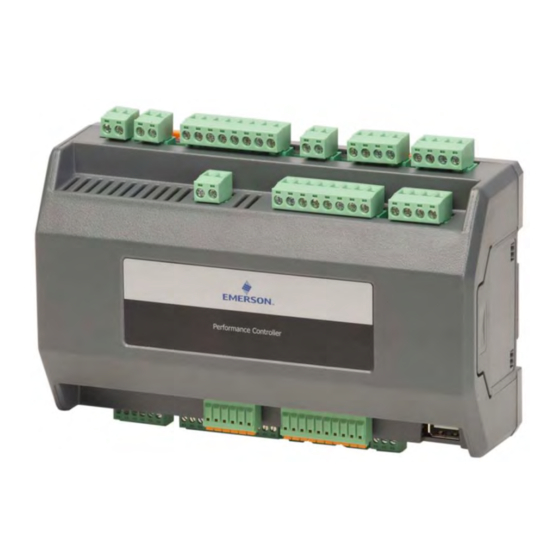
Product description General information about Emerson controllers PeC C100 and C200 Controllers PeC C100 & C200 are a range of parametric controllers developed and manufactured by Emerson. The system consists of a parametric controller and built-in EEV driver for bipolar valve, adapted to be used in any type of application in the commercial comfort sector. -
Page 8: Advanced Technical Information
▪ 2 digital inputs opto-isolated (24 – 230 VAC/DC) ▪ 2 EEV drivers (for bipolar valve) ▪ 1 input for backup power supply (will accommodate an XEC single or double valve, sold separately) Advanced technical information 2.3.1 PeC C100 controller Figure 1 2.3.1.1 Description of the connections... - Page 9 Connector Description Analog input connector P1, P2 = 4...20 mA Analog input connector T1 to T7 = NTC Analog 0-10 V demand signal (future use) RS485 connector: - RS485 master (Modbus RTU) communication to inverter RS485 connector, may be used for system controller interface / monitoring - RS485 slave (Modbus RTU) RS485 connector, may be used for system controller interface /...
- Page 10 12-bit A/D converter Number of inputs NTC Emerson (10 KΩ ± 1 % at 25 °C) -40 °C to 150 °C. NTC Emerson (100 KΩ ± 1 % at 25 °C) 0 °C to 170 °C Type of analog input...
- Page 11 230 VAC (5 A resistive, 2 A inductive cos φ 0.5) Maximum load Verify the capacity of the output used. Caution! There is double insulation between the digital outputs and the low voltage of the rest of the circuit. Table 6 2.3.1.6 Wiring diagram PeC C100 Figure 3 AGL_Sol_PEC_01_E_Rev01...
- Page 12 2.3.1.7 Mechanical specifications Figure 4: Dimensions of the PeC C100 2.3.1.8 Electrical specifications 24 VAC ± 10 %, 50/60 Hz Power supply 20-36 VDC Consumption 25 VA (VAC), 30 W (VDC) STELVIO CPM series (board), STELVIO CPF series Connectors (disconnectable)
-
Page 13: Pec C200 Controller
2.3.2 PeC C200 controller Figure 5 2.3.2.1 Description of the connections Connector Description Connector for 24 VAC/DC power supply (black colour) Green LED to indicate the presence of power supply Backup power supply for EXV closing in case of power failure. - Page 14 Connector Description Analog 0-10 V demand signal (future use) RS 485 connector: - RS485 master (Modbus RTU) communication to inverter RS485 connector, may be used for system controller interface / monitoring - RS485 slave (Modbus RTU) RS485 connector, may be used for system controller interface / monitoring or flashing - RS485 slave (Modbus RTU) USB port (any stick to be plugged into a PeC must be...
- Page 15 Input no. Type of input Description Common relay 4 (230 VAC, max, 5 A resistive, 2 A inductive cos φ 0.5 RL4-C switching capability) DI1 C Opto-insulated digital input 1 1(24-230 VAC/DC) Common opto-insulated digital input 1 DI2 C Potential free digital input 2 Potential free digital input 2 DI3 C Potential free digital input 3...
- Page 16 12-bit A/D converter Number of inputs NTC Emerson (10 KΩ ± 1 % at 25 °C) -40 °C to 150 °C. NTC Emerson (100 KΩ ± 1 % at 25 °C) 0 °C to 170 °C Type of analog input...
- Page 17 Figure 6: Temperature measurement accuracy (Total error) NTC 10 KΩ 2.3.2.4 Digital inputs Type Opto-insulated / free voltage contacts 1 DI 24-240 VAC/DC, opto-isolated Number of inputs 2 DI 24 VAC Dry contact, potential free Digital input status variation detection time 1 second Table 12 2.3.2.5...
-
Page 18: Usb-Rs485 Adapter (Optional Accessory)
Table 15 USB-RS485 Adapter (optional accessory) The PeC controllers can be connected to a computer via an Emerson external adapter. This adapter is not set up for fixed or continuous connection. If the adapter should be kept connected continuously, the room temperature must not exceed 50 °C. -
Page 19: Installation
Installation Important recommendations WARNING Conductor cables! Electrical shock! The controller operates at hazardous voltages which can cause severe personal injury or equipment damage. Extreme care and precautions must be taken when handling the product. The controller must not be opened. The controller must always be inserted inside an electrical panel that can only be accessed by authorised personnel. -
Page 20: Electrical Connection
Electrical connection General recommendations WARNING Conductor cables! Electrical shock! The controller operates at hazardous voltages which can cause severe personal injury or equipment damage. Extreme care and precautions must be taken when handling the product. The controller must always be inserted inside an electrical panel that can only be accessed by authorised personnel. -
Page 21: Power Supply
Always use safety transformers. ▪ PeC C100: 24 VAC ± 10 %, 50/60 Hz (consumption 25 VA) for the version with one EEV. ▪ PeC C200: 24 VAC ± 10 %, 50/60 Hz (consumption 50 VA) for the version with 2 EEV. -
Page 22: Pressure Transducers And Current Probes (4-20 Ma)
4.4.2 Potential free digital input DI2 and DI3 Refer to diagram in Figure 16 below and to Tables 3 & 10 for the numbering. The function is determined by the configuration (currently not in use). Figure 16: Digital inputs PeC C100 & C200 AGL_Sol_PEC_01_E_Rev01... -
Page 23: Connection Of The Digital Outputs
Connection of the digital outputs The digital outputs are isolated from one another (no common contact). The same voltage must always be used for the various groups of relays and within each group. For the electrical specifications, refer to the relative paragraphs of the different models and to Table 13. General overview of inputs and outputs 4.6.1 Circuit 1 –... -
Page 24: Circuit 2 (With Fixed-Speed Compressors Only) - Top Side
4.6.3 Circuit 2 (with fixed-speed compressors only) – Top side Figure 19: Circuit 2 top side – Power supply, digital outputs & EXV connections 4.6.4 Circuit 2 (with fixed-speed compressors only) – Bottom side Figure 20: Circuit 2 bottom side – Pressure and temperature inputs AGL_Sol_PEC_01_E_Rev01... -
Page 25: Electronic Expansion Valve Driver
Electronic expansion valve driver PeC C100 and PeC C200 are able to drive a wide range of stepper valves. Table 16 below shows the connection details. The power supply of the PeC C100 requires a TF25D transformer; for PeC C200 a TF50 transformer is required. -
Page 26: Digital Inputs And Outputs Wiring
4.8.2 Digital inputs and outputs wiring Modbus master DO3 (FS Scroll #6) DO2 (FS Scroll #5) DI1 (Feedback safety) Figure 22: Digital inputs and outputs wiring for variable speed circuit (proposal) DO8 (FS Scroll #6) DO7 (FS Scroll #5) DO6 (FS Scroll #4) DI4 (Feedback safety) Figure 23: Digital inputs and outputs wiring for fixed-speed circuit AGL_Sol_PEC_01_E_Rev01... -
Page 27: Certification & Approval
Certification & approval ▪ The controllers PeC C100 and C200 comply with the Low Voltage Directive LVD 2014/35/EU. The applied harmonised standards are: − EN 60335-1:2012/A11:2014: Household and similar electrical appliances - Safety - Part 1: Part 1: General requirements;... - Page 28 The Emerson logo is a trademark and service mark of Emerson Electric Co. Emerson Climate Technologies Inc. is a subsidiary of Emerson Electric Co. Copeland is a registered trademark and Copeland Scroll is a trademark of Emerson Climate Technologies Inc.. All other trademarks are property of their respective owners.