Makita DCS550 Technical Information
Cordless metal cutter 136mm 5-3/8"
Hide thumbs
Also See for DCS550:
- Instruction manual (72 pages) ,
- Instruction manual (57 pages) ,
- Instruction manual (32 pages)
Quick Links
T
ECHNICAL INFORMATION
Model No.
Description
C
ONCEPT AND MAIN APPLICATIONS
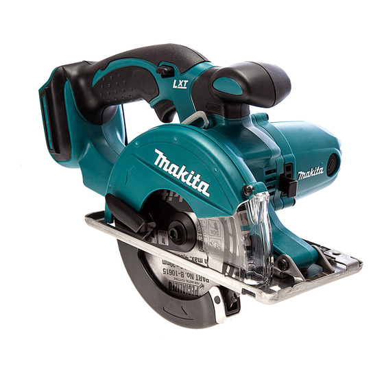
Model DCS550 is 136mm (5-3/8") Cordless Circular Saw
powered by 18V Li-ion battery BL1815N (1.5Ah), BL1820 (2.0Ah),
BL1830 (3.0Ah), BL1840 (4.0Ah) or BL1850 (5.0Ah).
Its main features are exactly the same as model BCS550 as follows:
・Well balanced tool design for high maneuverability regardless of
application direction; ensures easy handling even in overhead or
horizontal application.
・Compact and lightweight design
・51mm (2") Max cutting depth
・Soft grip
・Rigid base plate of stainless steel
・Large lock-off lever; easy to operate even with gloved hand
・Built-in twin LED job light illuminates the blade and cut line for accurate
cutting in the dark place.
・Large view window allows to easily cut along cut line.
Note: This model is not compatible with 1.3Ah battery BL1815.
S
pecification
Voltage (V)
18
Cell
Voltage: V
Capacity: Ah
Battery
Energy capacity: Wh
Charging time: min
No load speed: rpm= min
Size of blade:
mm (")
Max cutting
capacities: mm (")
Electric brake
Weight according to EPTA
Procedure 01/2003: kg (lbs)
O
ptional accessories
TCT Saw blade 136mm (5-3/8") 30T
TCT Saw blade 136mm (5-3/8") 50T
Guide rule
Compression spring 6
Screw M5x20
DCS550
Cordless Metal Cutter 136mm (5-3/8")
Cycle (Hz)
Current (A)
1.5, 2.0, 3.0, 4.0, 5.0
-1
Diameter
North American countries: 15.88 (5/8)
Hole diameter
Other countries: 20 (13/16)
at 0 degree
at 45 degrees
at 50 degrees
Two port multi fast charger DC18RD
Four port multi charger DC18SF
Fast charger DC18RC
Charger DC18SD
Charger DC24SC
Automotive charger DC18SE
H2
H1
Continuous Rating (W)
Input
Li-ion
18
27, 36, 54, 72, 90
15, 24, 22, 36, 45
with DC18RC
3,600
136 (5-3/8)
51 (2)
Yes
2.4 (5.3)
*1
OFFICIAL USE
for ASC & Sales Shop
PRODUCT
L1 L2
W2
Dimensions: mm (")
Length (L1)
348(13-3/4)
Width (W1)
180 (7-1/8)
Height (H1)
201 (7-7/8)
Height (H2)
145 (5-3/4)
Base Size: mm (")
Length (L2)
200 (7-7/8)
Width (W2)
106 (4-3/16)
*1 With BL1830/BL1840/BL1850
Max Output (W)
Output
370
S
tandard equipment
TCT Saw blade 136mm (5-3/8") 30T
Hex wrench
Safety goggle
Plastic carrying case/ Connector-
plastic case (type 3)
*2
Battery
*2
Battery cover
*3
Charger
*2
*2 Battery, Charger and Plastic-
carrying case/ Connector plastic-
case (type 3) are not supplied with
"Z" model.
*3 Supplied with the same quantity of
extra Battery
Note: The standard equipment may vary
by country or model variation.
Battery BL1850
Battery BL1840
Battery BL1830
Battery BL1820
Battery BL1815N
Battery protectors
P 1/ 13
W1
*1

Related Manuals for Makita DCS550


Summary of Contents for Makita DCS550
- Page 1 Cordless Metal Cutter 136mm (5-3/8") ONCEPT AND MAIN APPLICATIONS L1 L2 Model DCS550 is 136mm (5-3/8”) Cordless Circular Saw powered by 18V Li-ion battery BL1815N (1.5Ah), BL1820 (2.0Ah), BL1830 (3.0Ah), BL1840 (4.0Ah) or BL1850 (5.0Ah). Its main features are exactly the same as model BCS550 as follows: ・Well balanced tool design for high maneuverability regardless of...
-
Page 2: Necessary Repairing Tools
[2] LUBRICATION Apply the following grease to protect parts and product from unusual abrasion: Makita grease N. No.2 to the following portions designated with the black triangle Machine oil to the following portions designated with the gray triangle Portion to lubricate Lubricant Item No. - Page 3 P 3 /13 epair [3] DISASSEMBLY/ASSEMBLY [3] -1. Base DISASSEMBLING 1) Remove Blade cover (transparent part) by unscrewing Tapping screw 4x12. (Fig. 2) 2) Remove Rubber sleeve 6 and Sleeve 4 by unscrewing Tapping screw 4x25. (Fig. 3) Fig. 2 Fig.
- Page 4 P 4 /13 epair [3] DISASSEMBLY/ASSEMBLY [3] -1. Base (cont.) ASSEMBLING 1) Do the reverse of the disassembling steps. 2) After assembling Base to the machine, adjust the following portion for smooth adjustment of cut depth: A. Pan head screw M5 in the hinge portion of Base Fig.
- Page 5 P 5 /13 epair [3] DISASSEMBLY/ASSEMBLY [3] -2. Safety Cover Complete and Bearing Box Section (cont.) DISASSEMBLING 4) Remove Ball bearing 696ZZ from Bearing box section with 1R269. (Fig. 9) Fig. 9 5) Remove Retaining ring S-10 with 1R291. (Fig. 10) 6) Remove Spindle by following the steps below (Fig.
- Page 6 P 6 /13 epair [3] DISASSEMBLY/ASSEMBLY [3] -2. Safety Cover Complete and Bearing Box Section (cont.) ASSEMBLING 1) Assemble Bearing box section by doing the reverse of the disassembling steps, and install it on the machine. (Fig. 8 on page 4) Note: Before assembling Helical gear 23 to Spindle, make sure that O ring 26 is installed on Bearing box as illustrated to right in Fig.
- Page 7 P 7 /13 epair [3] DISASSEMBLY/ASSEMBLY [3] -3. Gear Unit (that engages with Armature) DISASSEMBLING 1) Remove Handle L from Handle R by unscrewing eight 4x18 Tapping screws. Remove the assembly of Gear housing and Motor section from Handle R by unscrewing three 4x35 Tapping screws. (Fig. 16) Fig.
- Page 8 P 8 /13 epair [3] DISASSEMBLY/ASSEMBLY [3] -3. Gear Unit (that engages with Armature) (cont.) ASSEMBLING 1) Assemble Helical gear 35 to Gear shaft by following the steps below (Fig. 21): 1. Put Gear shaft on 1R032 with the smaller diameter end of Gear shaft in the center hole of 1R032. 2.
- Page 9 P 9 /13 epair [3] DISASSEMBLY/ASSEMBLY [3] -4. Armature DISASSEMBLING 1) Remove Motor section and Gear housing from Handle R as illustrated in Fig. 16 on page 7. 2) Remove Carbon brush then Gear housing and Shaft lock. (Fig. 25) 3) Separate Housing R from Housing L by unscrewing four 4x18 Tapping screws.
- Page 10 P 10/13 epair [3] DISASSEMBLY/ASSEMBLY [3] -4. Armature (cont.) ASSEMBLING 2) Install Endbell complete on the commutator end of Armature. (Fig. 30) 3) Assemble Motor assembly (consisting of Armature, Yoke unit and Endbell complete) to Housing L. (Fig. 31) 4) Do the reverse of disassembling steps. (Figs. 25 and 26) Note: Make sure that Shaft lock is set in place before assembling Gear housing to Motor section.
-
Page 11: Circuit Diagram
P 11/ 13 ircuit diagram Fig. D-1 Color index of lead wires' sheath White Black Yellow White ③ ② Main switch ① Line filter Connectors (ø10-30: long length) Endbell LED switch + − Front Rear Terminal side side Viewed from the left side of machine Line filter... - Page 12 P 12/13 iring diagram [1] Wiring of LED Lead Wire on Blade Case Route as illustrated in Figs. D-2, D-3. Fig. D-2 Fig. D-3 Fix Protective tube that covers LED lead wires Pull out LED lead wires from the hole in Blade case with Lead wire holder on Blade case.
-
Page 13: Power Supply Circuit
P 13/ 13 iring diagram [3] Wiring in Handle Route Lead wires as illustrated in Fig. D-6. Fig. D-6 Power supply circuit Assemble Power supply circuit to Handle R with Lead wire (white) on Handle R side. Handle R Lead wire (white) Fix lead wires in lead wire holders as designated by arrows.