Table of Contents
Quick Links
Table of Contents

Related Manuals for GE Multilin EPM 2000 Series


Summary of Contents for GE Multilin EPM 2000 Series
- Page 1 GE Industrial Systems EPM 2000 Power Metering System INSTRUCTION MANUAL Manual P/N: 1601-0156-A2 Manual Order Code: GEK-106556A Copyright © 2005 GE Multilin GE Multilin 215 Anderson Avenue, Markham, Ontario Canada L6E 1B3 Tel: (905) 294-6222 Fax: (905) 201-2098 http://www.GEmultilin.com Internet:...
- Page 2 For customer or technical assistance, call: 1-888-GE4SERVICE (1-888-434-7378) Product Warranty GE warrants all products to be free from defects in material, workmanship and title and will be of the kind and quality specified in GE’s written description in the manual. The foregoing shall apply only to failures to meet said warranties, which appear within one year from the date of shipping.
-
Page 3: Table Of Contents
5.2.1. PT, CT Wiring Considerations 5.3. Voltage Signal Connections 5.3.1. PT Connections 5.3.2. Selecting the Voltage Fuses 5.4. Current Signal Connections 5.4.1. CT Connections 5.4.2. CT Polarity 5.4.2.1. CT Connection Reversal 5.5. Setup – System Type 5.6. Phase Labels GE Multilin Sub Meters... - Page 4 Modbus Registers 6.5. Register Map 6.5.1. RMS Total/Average Block 6.5.2. RMS Phase A Block 6.5.3. RMS Phase B Block 6.5.4. 6.5.5. RMS Phase C Block 6.5.6. Forward Integrator Block 6.5.7. 6.5.8. Favorite Block 6.5.9. 6.5.10. Display-Only Parameters GE Multilin Sub Meters...
-
Page 5: Overview
PT and CT ratios through the front panel keys. Otherwise, it will read your system incorrectly. GE stands behind your EPM 2000 products with complete User Support and Service. If the need arises, please do not hesitate to contact us at 1-888-GE4SERVICE (1-888-434-7378). -
Page 6: Physical Description
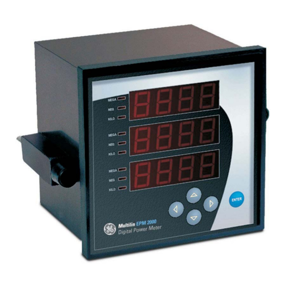
Name of the Parameter being displayed. The second key press takes you to the next page. Figure 1-2: The EPM 2000 front panel with display and keypad GE Multilin Sub Meters... -
Page 7: The Indicators
The maximum number the Meter handles is 9,999 G for RMS and Energy values. This means that the Energy readings of the meter will overflow between approximately 2 months to 3 years depending upon the PT and CT ratios programmed. See Table 2.6 “Integrator Overflow Period” GE Multilin Sub Meters... -
Page 8: The Keys
For full details, see the Keypad Operations Table. The left-most column (RUN, CLR, SET) constitutes the “Main Menu”. Press the key in the direction you want to go. Display shows where you’re headed. GE Multilin Sub Meters... - Page 9 Table 1-6: Menu and Display Map. Press the key that takes you in the desired direction. You can’t cross the thick boundary. Prog Main V, A, PF V1, V2, V3 Menu A1, A2, A3 Integ V pri A pri GE Multilin Sub Meters...
-
Page 10: Keys Example
Power 4 Quadrant, Energy 2 Quadrant. Provides 3D power computation for kVA • load bar graph for the quick estimation of consumption from a distance without touching any keys. • Customized new display for easy readability. GE Multilin Sub Meters... -
Page 11: Standard Measurements
Power factor, Per Phase & average • Active Energy, (kWh) Import/Export • Reactive Energy, (kVARh) (Ind / Cap) • Apparent Energy, (kVAh) * Additional error of 0.05 % of full scale for meter input current below 100 mA. GE Multilin Sub Meters... -
Page 12: Auxiliary (Control) Power Supply
Amps: 50mA – 6A, Overload: 10 A continuous, 50A for 3 seconds o Field configurable for 5 Amp or 1 amp secondary CTs o Burden (Load): Less than 0.2VA per Volts / Amps input o Frequency: 50 / 60Hz 45 – 65 Hz GE Multilin Sub Meters... -
Page 13: Safety Construction
1.3.9. Safety Construction Self extinguishable V0 plastic, double insulation at accessible area. • Pollution Degree II • Measurements Category III • See Chapter 4: Mechanical Installation. GE Multilin Sub Meters... -
Page 15: Quick Start Guide
Setup Meter Settings by going right. When done, go left back to the Main menu, go Up to Run then go Right in to RMS to view the Display Pages again. Figure 2-1: The Run Mode Flow chart GE Multilin Sub Meters... - Page 16 PROG V LL Legend keys keys V Ln key only A° 1 VA 1 VAR. 1 Intg VARh -VARh run.h On.h Intr RS-485 1.00 diAG 9600 status Evn 1 Factory 2000 QA only 03.01 01.00 GE Multilin Sub Meters...
- Page 17 Run hours. Total hours the Load was On. Accumulates when current is present. = ON hours. Total hours the meter was ON. Accumulates if auxiliary supply is present On.h On.h (irrespective of input signals). Intr Intr = Auxiliary interruption. Accumulates the auxiliary interrupt. GE Multilin Sub Meters...
-
Page 18: Auto-Scroll
(column in the above table). Press any key to revert to Manual Scrolling. • The Up key enters Limited Auto-scroll – within the same Group, eg only “RMS” or only “INTEG”. • The Down key enters Full Auto-scroll- down the entire column of pages. GE Multilin Sub Meters... -
Page 19: Turbo Key
Setup (Program) Mode. Optional parameters are in blue color. • If you’re lost, the TURBO key is a quick way to get back to the RMS home page. • Continuous pressing for 3 seconds initiates Auto-scrolling through the above Fav pages. GE Multilin Sub Meters... -
Page 20: Setup (Program)
Once you’re done, re-trace “run” You’re now back to the top of the Main Menu. Go . You’ll your path: see RMS. You can now go to view all the display Remember “Save Y” pages. GE Multilin Sub Meters... -
Page 21: Editing The Setup
EPM 2000 v03.01.01.00 Code Entry Use orkeys Main Use key only Menu Password Code Code To Prog Mode 1000 Prog To Run Mode Setup Name Value Save Value Enter the New Value. Figure 2-2a: Entering and Exiting Setup GE Multilin Sub Meters... - Page 22 To program via code entry Prog Fail, Code ‘y’ 20 0 0 View only Legend Use orkeys Pass 10 0 0 Use orkeys Fail view Code ‘n’ only Use key only Figure 2-2b: Code entry for Entering Setup GE Multilin Sub Meters...
- Page 23 Save ‘n’ 5.000 A. SEC LABL 5.000 A Sec LABL VA.Fn LABL VA.Fn 9600 baud VA.Fn 9600 baud Evn.1 Prty 9600 Baud Evn.1 Prty 1.000 Prty Evn.1 1.000 1.000 Figure 2-2c: The complete Setup (Program) menu GE Multilin Sub Meters...
- Page 24 NOTE: To discard present changes, press " " show “Save n”. Press to accept "y" (yes, save) "PASS" Stores the Setup changes. “Set” Now, you’re back in the Main Menu and can to “RUN” and to “RMS”. GE Multilin Sub Meters...
- Page 25 To program via code entry keys Prog Fail Code ‘y’ 2 0 0 0 keys View only key only Pass 10 0 0 Fail Code ‘n’ view only Intg ‘y’ Intg PASS Intg ‘n’ FAIL Figure 2-2d: Clearing the Integrator GE Multilin Sub Meters...
-
Page 26: Notes On The Energy Integrator
2 to 10.999 9.999x10 19.29 3.51 11 to 100.999 9.999x10 35.07 3.82 101 to 1000.999 9.999x10 35.07 3.82 1001 to 10000.999 9.999x10 35.07 3.82 10001 to 100000.999 9.999x10 35.07 3.82 Greater than 100001 9.999x10 35.07 3.82 GE Multilin Sub Meters... - Page 27 2.3. Summary We’ve now learned • to operate the EPM 2000 products. • to configure its Setup and • to Clear its Integrator. GE Multilin Sub Meters...
-
Page 28: Ac Power Measurement
Theorem states that in a power distribution network which has N conductors, the number of measurement elements required to determine power is N-1. A typical configuration of poly phase system has either a Delta connection or a Star (Wye) connection (see Figure 3-2, below). Sub Meters GE Multilin... -
Page 29: Consumption & Poor Pf
Which one ? U, Apparent, 3D (Factory setting) Best, all around Vector kVA where D = Distortion Power per IEEE 100 Good under Low Arithmetic, unbalance, to Arith match simpler Scalar kVA meters without 3D capability GE Multilin Sub Meters... -
Page 30: Mechanical Installation
CAUTION All Installation, wiring and maintenance instructions to be carried out by qualified personnel only. Please read this and the following chapter completely, before proceeding These diagrams display the various dimensions of mechanical installations. SIDE VIEW Sub Meters GE Multilin... - Page 31 FRONT VIEW REAR VIEW GE Multilin Sub Meters...
- Page 32 TOP VIEW RECOMMENDED CUTOUT 91 x 91 mm Sub Meters GE Multilin...
-
Page 33: Installation Process
Installation, wiring and periodic maintenance, must be done only by qualified personnel. Neither GE nor its agents may be held responsible for damage or death arising out of the wiring and / or PT, CT or other external circuits. -
Page 34: Viewing
While supporting the EPM 2000 from the front, tighten both side clamp screws in a criss-cross pattern till all slack is taken up, then apply one full turn. Do not over- tighten. Sub Meters GE Multilin... -
Page 35: Electrical Installation
Installation, wiring and periodic maintenance, must be done only by qualified personnel. Neither GE nor its agents may be held responsible for damage or death arising out of the wiring and / or PT, CT or other external circuits. -
Page 36: Auxiliary (Control) Power Supply
: Do not feed the EPM 2000’s auxiliary power supply terminals with a voltage greater than the rating marked on the label. The EPM 2000 will be permanently damaged and GE’s Warranty shall be void. 5.2. Potential Transformers and Current Transformers Large electrical installations have high voltages and currents which may exceed the direct connection rating of the meter. -
Page 37: Voltage Signal Connections
Install the wiring for the current circuit at 600V AC insulation as a minimum. The cable connection should be rated for 7.5 Amps or greater and have a cross-sectional area of 16 AWG minimum. GE Multilin Sub Meters... -
Page 38: Ct Connections
Energy parameters accumulate only one phase value. If two or all the phases of the CT are reversed, Energy will not accumulate. (Note that EPM 2000 does not have the export energy option). Sub Meters GE Multilin... -
Page 39: Ct Connection Reversal
Choose the diagram below that best describes your application. You must ensure that the CT phase and corresponding PT phase are identical and that the CT polarity is correct as explained in “CT Polarity” above. Follow the outlined procedure to verify correct connection. GE Multilin Sub Meters... -
Page 40: Epm 2000 Rear Panel
Six terminals for current, one “in” and one “out” per phase, • Four terminals for voltage, for three phases and neutral • Two terminals for meter Auxiliary Power Supply and • Two terminals for the RS 485 communications port. Figure 5-1: Meter Rear panel Sub Meters GE Multilin... -
Page 41: Three Phase 3 Wire Delta
With 2 CTs. Direct Voltage Connections if Voltages are less than 600v AC L-L. Otherwise, 3 PTs for Closed Delta or 2 PTs for Open Delta. Note: Remember to make sure Delta is programmed in the meter Setup. Leave the Vn terminal un-connected. Figure 5-2: The Delta Connection Diagram GE Multilin Sub Meters... -
Page 42: Three Phase 4 Wire Star (Wye)
For Single Phase, the same diagram is used except that only Phase 1 connections exist and Phase 2 and Phase 3 are unused. The unused current terminals must be shorted together to reduce noise picked up in the meter. Sub Meters GE Multilin... -
Page 43: Communication Installation
In cable runs longer than say 200 meters (650 feet), and with baud rates higher than 9600 baud, these benefits become more apparent. EPM 2000 Instruments (rear view) Figure 6-1: 2 Wire Half Duplex Communication Connection GE Multilin Sub Meters... - Page 44 Figure 6-: Closed Loop, 2 Wire Half Duplex RS485 Communication Connection Sub Meters GE Multilin...
-
Page 45: Repeaters
RS-485 Transceivers (Repeaters) are required for large networks of instruments. • In a two-wire connection, a maximum of instruments on one COM port of the PC can be included in the same network. • One RS 485 Segment can accommodate only 32 Devices. GE Multilin Sub Meters... -
Page 46: Factory Settings
Types (Integers and Floats) to transfer of Whole Block. • Each Modbus register size is 16-bits. All EPM 2000 readings are 32 bits. Therefore, each EPM 2000 reading occupies TWO consecutive Modbus Registers. • Most advanced SCADA packages will provide these capabilities. Sub Meters GE Multilin... -
Page 47: Register Map
3040 32-bit Float Voltage 3042 RMS Phase A Current 32-bit Float 3044 RMS Phase A Frequency 32-bit Float 3046 RESERVED2 Reserved for future use 32-bit Unsigned Long 3048 INTR Number of Power Interruptions 32-bit Unsigned Long GE Multilin Sub Meters... -
Page 48: Rms Phase B Block
3100 32-bit Float Voltage 3102 RMS Phase C Current 32-bit Float 3104 RMS Phase C Frequency 32-bit Float 3106 RESERVED4 Reserved for future use 32-bit Unsigned Long 3108 INTR Number of Power Outages 32-bit Unsigned Long Sub Meters GE Multilin... -
Page 49: Forward Integrator Block
3132 RESERVED7 Reserved for future use 32-bits 3134 RESERVED8 Reserved for future use 32-bits 3136 RESERVED9 Reserved for future use 32-bits RUN_SECS Forward Seconds Meter Load was 3138 32-bit Unsigned Long (Fwd) connected since last Reset GE Multilin Sub Meters... -
Page 50: Favorite Block
Voltage RMS Phase C Line to Neutral 3954 V 32-bit Float Voltage 3956 A RMS Phase C Current 32-bit Float 3958 VAh (Fwd) Forward Apparent Energy 32-bit Float 3960 Wh (Fwd) Forward Active Energy 32-bit Float Sub Meters GE Multilin... - Page 51 Hours available on the Meter Front Panel Display. Divide RunSecs by 3600 to get Run Hours. • No scaling or multiplication factor required. All values are already pre-scaled with the PT and CT scaling programmed into the meter. GE Multilin Sub Meters...
-
Page 52: Display-Only Parameters
Parameters Available on the Front Panel Display but not available on the RS485 communication port: Sl No Parameters available on Front Panel Display only Phase A Current Phase Angle Phase B Current Phase Angle Phase C Current Phase Angle On Hours END OF DOCUMENT Sub Meters GE Multilin...