
Related Manuals for GE Zenith Controls MX150


Summary of Contents for GE Zenith Controls MX150
- Page 1 GE Zenith Controls MX150 Microprocessor Controller Transfer Switch Control Panel 70R-2000B Operation and Maintenance Manual 5/03...
-
Page 2: Table Of Contents
It is designed to give highly accurate control of the transfer switch system. All GE Zenith transfer switches are designed for use on emergency or standby systems, and are rated for total system or motor loads. Transfer switches are UL Listed under Standard 1008 and CSA Certified under Standard C22.2 No. 178 and IEC Listed under Standard 947. -
Page 3: Safety
(Can Cause Severe Injury or Death) Turn OFF all power before installation, adjustment, or removal of transfer switch or any of its components. The safe operation of your switch is GE Zenith’s focus. Final Equipment Inspection The proper storage, installation, operation and mainte- Prior to energizing the transfer switch: nance will help increase the life of the switch. -
Page 4: Installation
14. Lock the enclosure. Initial Energization Before proceeding, refer to the information package GE Zenith Controls supplied with the ATS and read and understand the information on all accessories provided. Unlock the enclosure. SERIAL NUMBER: Open the enclosure. -
Page 5: Initial Energization
If Source 1 Available does not illuminate, verify that Source 1 Voltage is above the preset restore value. The Gen-Set will start and run while Source 2 stop Delay Timer is timing. GE Zenith Controls MX150 Operation and Maintenance Manual (70 -2000) -
Page 6: Control Connections
The engine start control wires connect to the for the engine start control wires. engine start relay terminals located to the left of the microprocessor. Figure 2 shows the location of these terminals. GE Zenith Controls MX150 Operation and Maintenance Manual (70 -2000) -
Page 7: Mx150 Microprocessor Controller
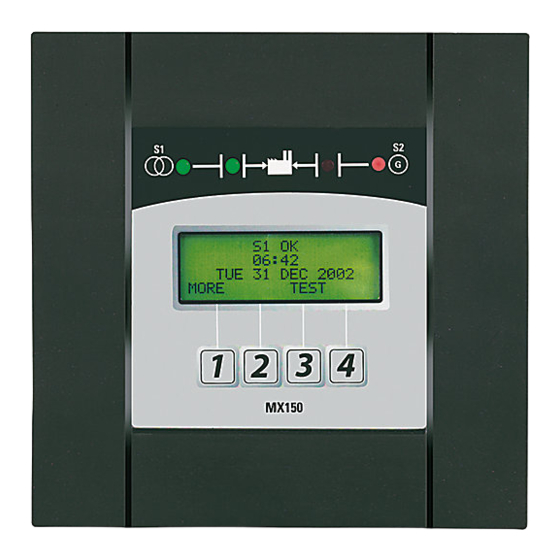
S 1 O K 2 1 : 5 6 M O N 2 3 A P R 2 0 0 2 M O R E T E S T MX150 Figure 7 GE Zenith Controls MX150 Operation and Maintenance Manual (70 -2000) -
Page 8: Lcd & Keypad
The word above the key changes depending on which changes depending on which changes depending on which screen is being displayed. screen is being displayed. screen is being displayed. Figure 8 GE Zenith Controls MX150 Operation and Maintenance Manual (70 -2000) -
Page 9: User Setting For Voltage & Frequency
Default is 20minutes. When exerciser is impending, (*E*) appears in the upper right hand corner of LCD screen. See page 13-14 for instructions. Configured via CFG (see page 16). Set via SET menu (see page 17). GE Zenith Controls MX150 Operation and Maintenance Manual (70 -2000) - Page 10 - If S1 and S2 Frequencies are identical, the display will show a series of alternating - - - - symbols (++++…) which also indicate the approximate out of phase degrees GE Zenith Controls MX150 Operation and Maintenance Manual (70 -2000)
-
Page 11: Standard Features, Mexeg Option Pkg
Generator and run under load. Can be configured by end user for 1, 7, 14, 28, 365 day cycle. GE Zenith Controls MX150 Operation and Maintenance Manual (70 -2000) -
Page 12: Optional Accessories
(40-600 Amp units) ZNET Network Communications Interface Card Heater and Thermostat. Manual Manual Transfer Switch transfers in either direction by depressing designated pushbuttons. Digital Power Meter with Display: Amps, Volts, and Frequency. GE Zenith Controls MX150 Operation and Maintenance Manual (70 -2000) -
Page 13: How To Set The System Clock
8. Press UP or DOWN to select DAILY, WEEKLY, 14 DAY, or 28 DAY as desired. 9. Press SAVE. 10. Press MORE to scroll to CONFG TIMER EXERCISER (XFR) or (NO XFR). GE Zenith Controls MX150 Operation and Maintenance Manual (70 -2000) - Page 14 If the CDT Exerciser is Factory configured for a No-Load Exerciser Or allow the controller to complete retransfer to Source 1 If the CDT Exerciser is Factory configured for a Load Exerciser GE Zenith Controls MX150 Operation and Maintenance Manual (70 -2000)
-
Page 15: Cdp Clock Exerciser
28-DAY and 365-DAY Exerciser Use to change values. (24 Hour System) To save value and to To previous field move cursor to next or to exit screen. field to be changed. GE Zenith Controls MX150 Operation and Maintenance Manual (70 -2000) -
Page 16: User Setup - Cfg Menu
N.O. N.C. To J2/J4 Input PROG 2 GRD (Input Sink) Controller ouputs have limited source capability. Use only GE Zenith - specified output modules. CON F IG NIA OUT ELEV. PRE. OUT USER S ET U P Output Contacts From J2/J4... -
Page 17: User Setup - Set Menu
N.C. To J2/J4 Input PROG 2 GRD (Input Sink) —SET SYSTEM CLOCK (pg.13) Controller ouputs have limited source capability. Use only GE Zenith - specified output modules. NIA OUT —DAYLIGHT SAVINGS ON/OFF ELEV. PRE. OUT Output Contacts From J2/J4 ALARM OUT Output —CLOCK EXERCISER (CDP) -
Page 18: User Setup - System Info
Next Impending Exerciser To J2/J4 Input PROG 2 GRD (Input Sink) (shows only if set) Controller ouputs have limited source capability. Use only GE Zenith - specified output modules. NIA OUT ELEV. PRE. OUT —SYSTEM INFO: Output Contacts From J2/J4... -
Page 19: Testing
"U" time delay if desired. Upon completion of the to Engine Stop "U") begins its cycle to allow Source 2 Engine (U) timing cycle, the controller sends an Engine stop signal. GE Zenith Controls MX150 Operation and Maintenance Manual (70 -2000) -
Page 20: Sequence Of Operation
S2 Stop S2 Start S2 Stable Time to S2 S1 Stable Time to S1 Delay Source 1 Transfer to Source 2 Transfer to Source 1 Engine Source 1 Fails Cooldown Returns GE Zenith Controls MX150 Operation and Maintenance Manual (70 -2000) -
Page 21: Relay/Transformer (R/T Box)
Description See Chart Transformer (1 VA) See Chart Transformer (25 VA) See Chart Transformer (25 VA) See Chart Transformer (1 VA) K-1274 Relay Flange Mounted K-1260 Coil Control Relay (24V) GE Zenith Controls MX150 Operation and Maintenance Manual (70 -2000) - Page 22 Coil Control Relay (24V) 50P-1014 208-220V K-3217 K-3225 50P-1015 230-240V K-3218 K-3226 50P-1016 277V K-3219 K-3227 50P-1017 380-400V K-3220 K-3228 50P-1018 416-440V K-3221 K-3229 50P-1019 460-480V K-3222 K-3230 50P-1020 575-600V K-3223 K-3231 GE Zenith Controls MX150 Operation and Maintenance Manual (70 -2000)
- Page 23 CCNO - COIL CONTROL RELAY (OPEN SOURCE 1) CCEO CCNO GROUND CCE - COIL CONTROL RELAY (SOURCE 2) CCN - COIL CONTROL RELAY (SOURCE 1) COMMON SINGLE PHASE SOURCE 2 SENSING 3-PHASE SOURCE 1 SENSING SOURCE 1 CONTROL POWER SOURCE 2 CONTROL POWER GE Zenith Controls...
-
Page 24: Troubleshooting & Diagnostics
Troubleshooting and Diagnostics DANGER HAZARDOUS VOLTAGES CAN CAUSE SEVERE INJURY OR DEATH. These charts may indicate problems that require authorized GE Zenith service personnel. Hazardous voltages may exist on termination plugs other than those that go into the MX150. General Troubleshooting The following troubleshooting guide is used to recognize, second suspected fault. -
Page 25: Maintenance And Testing
When performing a hi-pot or dielectric test on the power section, DISCONNECT the GE Zenith can provide complete preventative main- control panel plugs from the microprocessor tenance services. Please contact the GE Zenith Technical to avoid potential damage. Services Department for additional information. GE Zenith Controls... - Page 26 GE Zenith Controls MX150 Operation and Maintenance Manual (70 -2000)
- Page 27 GE Zenith Controls MX150 Operation and Maintenance Manual (70 -2000)
- Page 28 Zenith Controls A Product of GE Industrial Systems General Electric Company 830 West 40 Street, Chicago, IL 60609 USA 773 299-6600 , Fax: 773 247-7805 www.geindustrial.com...