Sunrise Medical Quickie Attitude Directions For Use Manual
Hide thumbs
Also See for Quickie Attitude:
- Directions for use manual (116 pages) ,
- Directions for use manual (112 pages)

Related Manuals for Sunrise Medical Quickie Attitude


Summary of Contents for Sunrise Medical Quickie Attitude
- Page 1 ADD ON BIKE AANKOPPELFIETS KIT HANDBIKE Attitude DIRECTIONS FOR USE GEBRUIKERSHANDLEIDING NOTICE D’UTILISATION Attitude Junior Attitude Hybrid 000690707.02...
- Page 2 Add-on Bike Components We at SUNRISE MEDICAL have been awarded the ISO-9001 certificate, which affirms the quality of our products at every stage, from R&D to production. This products meet the requirements in accordance with EC guidelines. Options or accessories shown are available at extra cost.
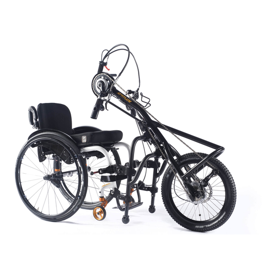
- Page 3 Attitude: Attitude: Attitude : 1. Front wheel 1. Voorwiel 1. Roue avant 2. Fork 2. Vork 2. Fourche 3. Handle 3. Hendel 3. Poignée 4. Hubmotor 4. Naafmotor 4. Moyeu de roue 5. Crank with handle 5. Crank met handvat 5.
-
Page 4: Table Of Contents
Contents Definitions Definitions Definitions of words used in this manual Foreword Word Definition Area of application Advice to the user of potential risk of 1.0 General safety notes and driving limits serious injury or death if the advice DANGER! Safety instructions – prior to each ride. is not followed Safety instructions –... -
Page 5: Foreword
The serial number label is located on the frame as well as in the owner’s manual. For Sunrise Medical, it is very important that we have a good relationship with our customers. We like to keep you up-to-date Warranty can only be taken on if the product is used under the about new and current developments at our company. -
Page 6: General Safety Notes And Driving Limits
• You should only use product combinations which have been WARNING! approved by Sunrise Medical. • NEVER exceed the maximum load of 100 kg for driver DANGER! excluding any items carried on the add-on bike. -
Page 7: Safety Instructions - Prior To Each Ride
Safety instructions – prior to each ride. • Driving on stairs is not permitted. • Obstacles e.g. curbs must be run over always frontal / rectangular with very low speed to avoid tipping over and CAUTION! potential injuries. The max obstacle height is 50.0 mm, but •... -
Page 8: Warranty
2. To enforce the warranty, please contact Sunrise Medical Customer Service with the exact details of the nature of the difficulty. Should you be using the product outside the area covered by the Sunrise Medical customer service agent, repairs or replacement will be carried out by another agency as designated by the manufacturer The product must be repaired by a Sunrise Medical designated Customer Service agent, (dealer). -
Page 9: Handling
The add-on bike must be handed over ready to use from Sunrise Medical or an authorized Sunrise Medical dealer. • Before using for the first time, the battery should be fully charged. -
Page 10: Adjusting The Pedal Position
The default position of the crank is based on data which dipicts the average best fit. If this is not suitable for you, please contact your authorized Sunrise Medical dealer. The pedal position can be adjusted to the user, (arm length and... - Page 11 Fig.4.6 S = 25 mm Docking top Docking bottom (X) mm (Y) mm (S) mm (a) mm (L) mm position 1 position 1 75 - 95 position 1 position 1 75 - 95 position 1 position 1 75 - 95 position 1 position 1 75 - 95...
-
Page 12: Adjusting The Connecting Frame
5.0 Adjusting the Connecting Frame Fig.5.1 Adjustment: The connecting frame can be extended by approximately 20mm to fit a wheelchair with a wider front frame. Therefore the 12 allen screws on the top and bottom cover of the adjuster clamp need to be loosened. The connecting frame can then be pulled out on both sides, (Fig.5.1). -
Page 13: Docking And Dedocking
6.0 Docking and Dedocking Fig.6.1 WARNING! • Always make sure that the device is switched off before docking and dedocking. • Ensure the wheelchair is fully connected with the add-on bike before use, by using the handgrip A. • As with all moving parts, there is a risk that fingers and / or clothing could become trapped. -
Page 14: Docking: Fig.6.6 - Fig.6.10
De-Docking: Fig.6.6 - Fig.6.10 Fig.6.7 WARNING! The de-docking procedure should take place on an even surface. NOTE: De-docking follows the opposite sequence as described for Docking. • Lock the wheelchair brakes. • Open the red locking levers, A. • Push the add-on bike forward/upwards until the upper docking connector has no contact with the front frame of your wheelchair, B. -
Page 15: Functional Components
7.0 Functional Components Fig.7.1 Connecting frame (Fig.7.1): The connecting frame acts as a parking stand, and fascilitates easy docking/manoeuvring when the add-on bike is disconnected from the wheelchair. The height of the stand wheels can be adjusted using the bolts, (A). - Page 16 WARNING! WARNING! • If the main brakes should fail, then the parking brakes may • The braking effect will be greatly reduced if the surface is be used once for emergency braking. wet, dirty, sandy, stoney, uneven or otherwise compromised •...
-
Page 17: Coaster Brake (Fig.7.5)
Coaster brake (Fig.7.5): Fig.7.5 The coaster brake option allows you to brake by pedalling backwards. This option is required particularly for users with restricted or no finger function. The braking system can only be uncoupled for manoeuvring (Fig.7.5) by moving the lever A. When riding or moving forward, the system will be put automatically back into an operational position. -
Page 18: Angle- And Depth Adjustment Of The Crank Position
Angle- and depth adjustment of the crank position Fig.7.9 If your Attitude is equipped with the optional angle- and depth adjustment, you can adjust the angle and the length of the frame using a hinge and a telescopic tube on the upper part of the frame. Adjusting the angle of the frame (Fig.7.9): •... -
Page 19: Length-Adjustment Of The Cranks (Attitude Junior Only)
• Locate the quick-lock (A) on your chain, clean the area Fig.7.12 around the quick-lock, hold the chain-links left and right of the quick-lock firmly and push them against each other (Fig.7.12). • Insert the chain extension, re-assemble the quick-locks (A) on both sides and close them by pulling them apart (Fig.7.13) The tension of the chain is correct when it can be tensioned manually in the middle of the chain by approx. -
Page 20: Maintenance
8.0 Maintenance Before any maitenance is started, turn the battery off and remove it. NOTE: All Service and Maintenance proceedures carried out on the Add-on Bike require the Battery Locking Key. Without this key no maintenance is possible. Checks to be carried out before use: When What Comments... -
Page 21: Service Period
If you have any questions or require any help, please contact • If needed only use a little water. your authorized Sunrise Medical dealer, who will be pleased to • Handles, display and battery may only be cleaned by wiping advise you with regards to servicing and repairs. -
Page 22: Disposal / Recycling Of Materials
All weight/ dimensions and performance data is approximate and is provided solely for guidance. All products from Sunrise Medical comply with the 93/42/EEC directive for medical products. All add-on bikes must be used in accordance with the manufacturer’s guidelines. -
Page 23: Torque
15.0 Torque 16.0 Technical Data General Torque Settings: max user weight 100 kg Torque in general is 7 Nm, unless otherwise specified. Seat width range wheelchair 280 - 460 mm The screws used are fitted with threadlock at the factory and Weight (cpl) 21,5kg can be adjusted up to 5 times after fitting. - Page 24 Attitude Hybrid Section Neodrives System Part 1 Neodrives sMMI and Motor Part 2 Neodrives Battery Attitude/Attitude Hybrid Rev.3.0...
- Page 25 Contents Part 1 Neodrives sMMI and Motor Part 2 Neodrives Battery 1.0 Safety Advice/Instructions 4.0 Introduction Intended use of the neodrives components: Signs and symbols: Permissible operating conditions / operating sites: Permissible operating conditions / operating sites: Standard scope of delivery (neodrives components): 2.0 Standard Scope of Delivery Neodrive Components: 5.0 Technical Data...
-
Page 26: Part 1 Neodrives Smmi And Motor
WARNING! Part 1 Neodrives sMMI and Motor Before using the device, carefully read all safety and hazard information contained in the individual chapters 1.0 Safety Advice/Instructions of this operating manual and all other enclosed documents. WARNING! It is not a legal requirement at present to wear a helmet when Permissible operating conditions / operating sites: using a add-on bike, nevertheless for your own safety, wearing a helmet is recommended! -
Page 27: Standard Scope Of Delivery
2.0 Standard Scope of Delivery Neodrive Components: • Drive motor. • Smart MMI (display) incl. dock. • This operating manual. Technical Data: Drive Range*: 120 km Speed 25 km/h Power rating (peak) 250 Watt (650 Watt) Operating voltage 36 Volt Rated torque 12 Nm Peak torque... -
Page 28: Smart Man-Machine Interface (Smmi)
3.0 smart Man-Machine Interface (sMMI) Fig.3.1 Controller: The controller fitted to the handlebar of your Pedelec is used to access menus and activate functions in the sMMI. The following functions are stored: Button 1 = UP (one step upwards) Button 2 = confirm menu key or selection Button 3 = DOWN (one step downwards). -
Page 29: Fitting And Removing The Smmi
Fitting and removing the sMMI Fig.3.2 Fitting: • Place the sMMI [4] in the correct position, (the neodrives logo faces the rider) and skewed at an angle of about 30 degrees to the dock [5] (Fig.3.1). • Turn the sMMI [4] on the dock [5] using slight pressure by 30 degrees clockwise so that both components are in alignment, (Fig.3.2). -
Page 30: Start Menu
Start menu: NOTE: When the add-on bike is idle please note: • If the pushing aid is activated, you can adjust the assistance As described previously, when starting up, the start menu levels from a travel speed of about 8 km/h. illustrated in the accompanying image appears, (Fig.3.6). -
Page 31: Activating Recuperation
Activating recuperation: Fig.3.8 By activating the recuperation function you can recover energy when travelling and store it in the battery. This is possible or useful from a speed of 15 km/h. Activating recuperation and adjusting is carried out using buttons [1] and [3] of the controller. -
Page 32: Braking Assistant
Braking assistant: Fig.3.9 Before travelling, if you wish, the braking assistant can be activated. This supports you when braking and ensures energy recovery to the battery (if this is not charged above the limit of 90 % or the temperature is not below 0 °C). To activate braking assistance, in the start menu (see section 3.2.2), press button [2] on the controller to move to the next sub menu. -
Page 33: Pushing Aid
Pushing aid: Fig.3.10 Should you require motorised support when pushing, for example on steep hillsides, then you can activate the pushing aid. To do this, while you are in the start menu (see section 3.2.2), press button [2] on the controller to move to the next sub menu. -
Page 34: Travel Modes
Travel modes: The following denote: There are three travel modes stored in the sMMI – BOOST, Current time (needs a pre-setting, see section 3.2.8). TOUR and ECO. Displays the distance you have covered (needs a “tour reset”). Navigate using the controller buttons (see section 2) to the In Eco mode the torque and therefore the maximum available function “tour reset”... -
Page 35: Information And Warning Symbols
Information and warning symbols: Fig.3.12 As standard, in field [11], the remaining battery capacity is displayed. But depending on the travel situation, information and warnings as shown in the following may also be displayed in this field. Battery capacity display (standard display): The remaining battery capacity is shown in stages by a decreasing white bar. -
Page 36: Easy Display Mode
Easy Display mode: Fig.3.14 By activating Easy Display, the following graphical symbols presented in section 3.2.2 are enlarged on the display. •• indication of the current speed travelled •• indication of the daily kilometres travelled (requires prior reset, see section 3.2.10) ••... -
Page 37: Programming Options By The Specialist Dealer
Programming options by the specialist dealer: Your specialist dealer can tailor the travel characteristics of your add-on bike to your requirements using a diagnosis and programming software. Generally, the factory settings are ideally tailored to the respective model and do not need to be changed. The factory settings may vary depending on your bicycle model (mountain bike / trekking). -
Page 38: Note On The Smmi Plugs: (Fig.3.15)
Note on the sMMI plugs: (Fig.3.15) Fig.3.15 If you need to remove the sMMI plugs leading to the battery at any time, please note the following information when connecting them again: • The plug of the sMMI and the socket on the additional cable to the battery must be correctly aligned when connecting. -
Page 39: Motor
Fig.3.17 CAUTION! The motor must never be “forcibly cooled” externally with water. This can lead to damage and does not help especially with cooling as it is primarily the inside of the motor that is hot. Motor: The drive wheel of your Pedelec can be removed from the bicycle frame at any time, for example, for cleaning purposes or in case of a puncture. -
Page 40: Attaching The Drive Wheel
Attaching the drive wheel: Fig.3.18 Make sure that all the components attached to the wheel have been installed in accordance with the instructions and specifications of the respective manufacturer. This relates in particular to the brakes and the gear box. Do not forget to reinstall the torque support [20] in the same position as it was taken from. -
Page 41: Cleaning The Motor And Smmi
Cleaning the motor and sMMI: Transportation: When cleaning the device, never use cleaning benzine, thinner, The following information needs to be noted when transporting acetone or similar agents. Never use abrasive detergents or the Pedelec by car. aggressive cleaning agents. Instead, use only conventional ••... -
Page 42: Error Indications And Possible Remedies
Error indications and possible remedies: The system cannot be turned on. • Is the battery correctly inserted in it's holder? • Are all the plugs connected correctly? • Are there ant deposits, (e.g.metal filings), on the magnetic plug on the battery? •... -
Page 43: Introduction
Signs and symbols: Part 2 Neodrives Battery Important information for your safety are identified in this operating manual as follows: 4.0 Introduction Word Definition Introduction: Advice to the user of potential risk of Important instructions : serious injury or death if the advice DANGER! Along with this operating manual, your add-on bike is not followed... -
Page 44: Technical Data
5.0 Technical Data Category ICR18650MG1 Battery type: Lithium ion Rated capacity: 14.5 Ah Rated voltage: 36.2 V End-of-charge voltage 42 V Total energy: 515 Wh Maximum discharge current: 30 A Ambient charging temperature: 0 °C to 40 °C Ambient operating temperature: -20 °C to 60 °C Ambient storage temperature: +10°C to +30°C... -
Page 45: Safety Instructions And Precautions On The Use Of The Battery
Safety instructions and precautions on how to store 6.0 Safety Instructions/Precautions the battery: •• Protect the battery immediately upon separating from the WARNING! battery charger or motor. Never allow any moisture or foreign • Read and observe the following safety instructions and particles (e.g. -
Page 46: Safety Information And Precautions On How To Transport And Ship The Battery
Safety information and precautions on how to •• Do not operate the charger if the power cable, the charging cable or the plugs attached to the cables are damaged. transport and ship the battery: Damaged parts must be replaced immediately by the Lithium-ion cells are used in the neodrives battery. -
Page 47: Starting Up
Fig.7.1 7.0 Operation Starting up: Information on the operating modes: Essentially, the battery has two operating modes. It is either in “Active mode” or in “Deep Sleep mode”. In Active mode the battery consumes at least 5 mA per hour (consumption of the battery’s own electronics). -
Page 48: Battery Capacity Indicator
Battery capacity indicator: Fig.7.4 You can check the battery capacity at any time using the LED display. If the battery has not been used for more than 48 hours: • Tap button [4]. • The battery is switched on, all LEDs (a – e) flash three times. •... -
Page 49: Detaching The Battery
Detaching the battery: Fig.7.5 Switching off the battery: The battery is switched off using the sMMI controller (see the sMMI and motor operating manual). This puts the battery initially in Active mode for 48 hours. This means that, within this period, the sMMI can be reactivated at any time without having to first switch on the battery. -
Page 50: Charging The Battery
Charging the battery: Fig.7.8 Fully charge the battery before its first use. The battery capacity upon delivery is generally 30%. The battery can be charged at any capacity without adversely impacting its service life. The battery achieves its maximum service life when it is charged at an ambient temperature of between 10 °C and 30 °C Connecting the battery charger:... -
Page 51: Keys
•• The battery must never be sprayed with a steam cleaner or the battery has been / is used contrary to the intended use. similar device. Sunrise Medical GmbH Kahlbachring 2-4 69254 Malsch/Heidelberg Deutschland Tel.: +49 (0) 7253/980-0... - Page 52 Inhoudsopgave Definities Definities Betekenis van woorden die in deze handleiding worden Voorwoord gebruikt. Gebruik Woord Betekenis Toepassingen De gebruiker wordt 1.0 Algemene veiligheidstips en rijbeperkingen Veiligheidsvoorschriften - controle voor iedere rit. geattendeerd op de kans op Veiligheidsvoorschriften - tijdens het rijden ernstig letsel of overlijden GEVAAR! Veiligheidsvoorschriften - nadat u de aankoppelfiets hebt...
-
Page 53: Voorwoord
Is er geen erkende dealer in uw regio of hebt u vragen, neem verkeersregels wanneer deze wordt gebruikt op openbare dan schriftelijk of telefonisch contact op met Sunrise Medical: wegen, stoepen en in openbare ruimtes. Het maximum gebruikersgewicht is 100kg. De maximale belasting voor mee te nemen voorwerpen, bijv, in fietstassen, is Sunrise Medical B.V. -
Page 54: Algemene Veiligheidstips En Rijbeperkingen
1.0 Algemene veiligheidstips en rijbeperkingen • Gebruik 's nachts en bij schemering altijd de verlichting. • Wanneer u lange afstanden wilt afleggen, adviseren we een De technologie en constructie van deze aankoppelfiets zijn reserve batterij mee te nemen. ontworpen met het oog op maximale veiligheid. Aan de •... -
Page 55: Veiligheidsvoorschriften - Controle Voor Iedere Rit
Veiligheidsvoorschriften - controle voor iedere rit. • Op hellingen is de tractie van het aandrijfwiel minder en het remmende effect is hierdoor aanzienlijk kleiner. De rijstijl en snelheid moeten altijd worden aangepast zodat het product OPGELET! veilig tot stilstand gebracht kan worden. •... -
Page 56: Garantie
De garantie geldt slechts voor fabricagefouten. 2. Om de garantie ten uitvoer te brengen, kunt u contact opnemen met de klantenservice van Sunrise Medical met de exacte gegevens over het probleem. Indien u het product gebruikt buiten het gebied dat wordt gedekt door de klantenservice van Sunrise Medical, wordt de reparatie of vervanging uitgevoerd door een ander servicepunt welke door de fabrikant wordt aangewezen. -
Page 57: Gebruik
• De aankoppelfiets mag uitsluitend worden gebruikt in combinatie met het meegeleverde aankoppelsysteem en de juiste koppelingspennen voor uw rolstoel. De aankoppelfiets moet klaar voor gebruik door Sunrise Medical of een erkende Sunrise Medical dealer worden overhandigd. • Voordat u de aankoppelfiets voor de eerste maal gebruikt, moet de accu volledig worden opgeladen. -
Page 58: Aanpassen Van De Pedalen
4.0 Aanpassen van de pedalen Fig. 4.1 Aanpassing: De standaardpositie van de crank is gebaseerd op gegevens omtrent de gemiddelde gebruiker. Als deze positie voor u niet geschikt is, neem dan contact op met uw erkende Sunrise Medical dealer. Bovenzijde De positie van de pedaal kan worden aangepast aan de aankoppelsysteem Bovenzijde... - Page 59 Fig.4.6 S = 25 mm Bovenzijde Onderzijde (X) mm (Y) mm (S) mm (a) mm (L) mm aankoppelsysteem aankoppelsysteem positie 1 positie 1 75 - 95 positie 1 positie 1 75 - 95 positie 1 positie 1 75 - 95 positie 1 positie 1 75 - 95...
-
Page 60: Aanpassen Van Het Aankoppelframe
5.0 Aanpassen van het aankoppelframe Fig. 5.1 Aanpassing: Het aankoppelframe kan ongeveer 20mm worden verlengd zodat het ook past op een rolstoel met een breder voorframe. Hiertoe moeten de 12 inbusschroeven op de boven- en onderzijde van de stelklem worden losgedraaid. Het aankoppelframe kan vervolgens aan beide zijden worden uitgetrokken (Fig. -
Page 61: Aan- En Afkoppelen
6.0 Aan- en afkoppelen Fig. 6.1 WAARSCHUWING! • Controleer altijd of het apparaat uitgeschakeld is voordat u aan- of loskoppelt. • Controleer voor gebruik of de rolstoel volledig is aangesloten op de aankoppelfiets, door handgreep A te gebruiken. • Bij bewegende delen is er altijd een risico dat vingers en/of kleding beklemd raken. -
Page 62: Afkoppelen: Fig. 6.6 - Fig. 6.10
Afkoppelen: Fig. 6.6 - Fig. 6.10 Fig. 6.7 WAARSCHUWING! Het afkoppelen moet plaatsvinden op een vlakke ondergrond. OPMERKING: Om af te koppelen volgt u de procedure voor aankoppelen in omgekeerde volgorde. • Zet de rolstoel op de rem. • Open de rode vergrendelingshendels, A. •... -
Page 63: Functionele Onderdelen
7.0 Functionele onderdelen Fig. 7.1 Fietsstandaard (Fig. 7.1): De fietsstandaard heeft een functie als parkeerhulp en maakt het gemakkelijk om de aankoppelfiets aan- en af te koppelen en te manoeuvreren wanneer deze wordt losgemaakt van de rolstoel. Met behulp van de bouten (A) kan de hoogte van de steunwieltjes worden aangepast. - Page 64 WAARSCHUWING! WAARSCHUWING! • Mochten de hoofdremmen het niet doen, dan kan - in een • Het remmende effect wordt voor een groot deel verminderd noodgeval - de parkeerrem eenmalig worden gebruikt om te als de bodem nat, vies, zanderig, stenig, ongelijk of remmen.
-
Page 65: Terugtraprem (Fig. 7.5)
Terugtraprem (Fig. 7.5): Fig. 7.5 Met de terugtraprem kunt u remmen door de pedalen achterwaarts te bewegen. Deze optie is vooral nodig voor gebruikers met geen of beperkt gebruik van vingers. Het remsysteem kan alleen worden ontkoppeld om gemakkelijker te manoeuvreren (Fig. 7.5) door hendel A te bewegen. -
Page 66: Aanpassing Hoek En Diepte Van De Crank-Positie
Aanpassing hoek en diepte van de crank-positie Fig. 7.9 Als uw Attitude is voorzien van de mogelijkheid om de hoek en diepte aan te passen, kunt u de hoek en lengte van het frame aanpassen via de scharnierverbinding en telescopische buis op het bovendeel van het frame. -
Page 67: Aanpassing Van De Lengte Van De Cranks (Uitsluitend Bij De Attitude Junior)
• Zoek de snelkoppeling (A) op de ketting en maak het gebied Fig. 7.12 rond de snelkoppeling schoon. Houd de schakels links en rechts van de snelkoppeling stevig vast en duw ze tegen elkaar (Fig. 7.12). • Plaats de kettingverlenging ertussen, maak de snelkoppelingen (A) aan beide kanten weer vast en sluit ze door ze uit elkaar te trekken (Fig. -
Page 68: Onderhoud
8.0 Onderhoud Voordat onderhoud wordt uitgevoerd, dient u de accu uit te schakelen en te verwijderen. OPMERKING: Voor alle service- en onderhoudsprocessen die op de aankoppelfiets worden uitgevoerd, is de accuvergrendelingssleutel nodig. Zonder deze sleutel is onderhoud niet mogelijk. Controles uit te voeren voor ieder gebruik: Wanneer Opmerkingen •... -
Page 69: Onderhoudstermijn Onderhoud
Als u vragen hebt of hulp nodig hebt, kunt u altijd contact nemen. opnemen met uw erkende Sunrise Medical dealer. Hij zal u • Gebruik indien nodig uitsluitend een beetje water. graag adviseren ten aanzien van onderhoud en reparaties. -
Page 70: Afvalverwerking / Recycling Van Materialen
Wanneer u zijn bij benadering en dienen slechts als richtlijn. vervangingsonderdelen bestelt of een schadeclaim indient, Alle producten van Sunrise Medical voldoen aan de 93/42/ moet u de volgende gegevens vermelden: EEG-richtlijnen voor medische producten. Alle aankoppelfietsen moeten worden gebruikt in overeenstemming met de aanwijzingen van de fabrikant. -
Page 71: Koppel
15.0 Koppel 16.0 Technische gegevens Algemeen Vereiste draaikracht (torque): max. gebruikersgewicht 100 kg De draaikracht is in het algemeen 7 Nm, tenzij anders is Zitbreedte range rolstoel 280 - 460 mm gespecificeerd. Gewicht (cpl) 21,5 kg De schroeven worden in de fabriek met schroefdraadborging Wielmaat 20"... - Page 72 Attitude Hybrid onderdeel Neodrives Systeem Part 1 Neodrives sMMI en Motor Part 2 Neodrives Accu Attitude/Attitude Hybrid Rev.3.0...
- Page 73 Inhoudsopgave Part 1 Neodrives sMMI en Motor Part 2 Neodrives Accu 1.0 Veiligheidsadvies/Instructies 4.0 Inleiding Bedoeld gebruik van de neodrive onderdelen: Tekens en symbolen: Toegestane gebruiksomstandigheden / gebruikslocaties: Toegestane gebruiksomstandigheden / gebruikslocaties: Standaard leveringsomvang (neodrives onderdelen): 2.0 Standaard Leveringsomvang Neodrive onderdelen: 5.0 Technische gegevens Technische gegevens: Overzicht hoofdelementen:...
-
Page 74: Part 1 Neodrives Smmi En Motor
WAARSCHUWING! Part 1 Neodrives sMMI en Motor Lees voordat u dit apparaat gebruikt aandachtig alle veiligheids- en gevareninformatie door in de 1.0 Veiligheidsadvies/Instructies afzonderlijke hoofdstukken van deze gebruikershandleiding en alle andere bijgesloten WAARSCHUWING! documenten. Het is geen wettelijk vereiste om een helm te dragen wanneer u de aankoppelfiets gebruikt, maar voor uw eigen veiligheid wordt Toegestane gebruiksomstandigheden / het dragen van een helm aanbevolen! -
Page 75: Standaard Leveringsomvang
2.0 Standaard Leveringsomvang Neodrive onderdelen: • Aandrijfmotor • Smart MMI (display) incl. dock. • Deze gebruikershandleiding Technische gegevens: Rijden Bereik*: 120 km Snelheid*: 25 km Vermogen (piek) 250 watt (650 watt) Bedrijfsspanning 36 volt Torque nominaal 12 Nm Torque piek 40 Nm Efficiëntieniveau 80 % (incl. -
Page 76: Smart Man-Machine Interface (Smmi)
3.0 smart Man-Machine Interface (sMMI) Fig. 3.1 Bediening: Het bedieningspaneel dat aan het stuur van uw Pedelec is bevestigd, wordt gebruikt om toegang te verkrijgen tot de menu’s en om de functies van de sMMI te activeren. De volgende functies worden opgeslagen: Knop 1 = UP (één stap omhoog) Knop 2 = bevestig menu toets of selectie Knop 3 = DOWN (één stap omlaag) -
Page 77: Monteren En Verwijderen Van De Smmi
Monteren en verwijderen van de sMMI Fig. 3.2 Bevestiging: • Plaats de sMMI [4] in de juiste positie, (het neodrives logo wijst naar de bestuurder) en met een hoek van ongeveer 30° ten opzicht van het station [5] (Fig. 3.1). •... -
Page 78: Startmenu
Startmenu: OPMERKING: Let op! Als de aankoppelfiets stil staat: • Als de duwondersteuning wordt geactiveerd kunt u de Als hierboven beschreven, verschijnt bij het opstarten het assistentieniveaus afstellen vanaf een rijsnelheid van startmenu als afgebeeld in de begeleidende afbeelding (Fig. ongeveer 8 km/u. -
Page 79: Activeer Terugwinning
Activeer terugwinning: Fig. 3.8 Door het activeren van de terugwinfunctie kunt u energie terugwinnen bij het rijden en dit opslaan in de accu. Dit is mogelijk of nuttig bij een snelheid vanaf 15 km/u. Het activeren en afstellen van de terugwinning wordt uitgevoerd met knop [1] en [3] van het bedieningspaneel. -
Page 80: Remassistent
Remassistent: Fig. 3.9 Voordat u gaat rijden kunt u naar wens de remassistent inschakelen. Dit ondersteunt u bij het remmen en zorgt voor energieterugwinning naar de accu (als deze niet boven het limiet van 90% is opgeladen en de temperatuur niet lager is dan 0°C). -
Page 81: Duwondersteuning
Duwondersteuning: Fig. 3.10 Wanneer u gemotoriseerde ondersteuning nodig hebt bij het duwen, bijvoorbeeld om steile hellingen op te komen, dan kunt u de duwondersteuning activeren. Om dit te doen drukt u terwijl u in het startmenu bent (zie hoofdstuk 3.2.2) op knop [2] op het bedieningspaneel om naar het volgende submenu te gaan. -
Page 82: Rijmode
Rijmode: Het volgende betekent: Er zijn drie rijmodus opgeslagen in het sMMI – BOOST, TOUR Huidige tijd (heeft een voorinstelling nodig, zie hoofdstuk 3.2.8) en ECO. Geeft de afstand weer die u hebt afgelegd (vereist een "tour reset" (trip reset)). Navigeer met gebruikmaking van de In de ECO-modus wordt de torque, en daardoor het maximaal bedieningsknoppen (zie functie 2) naar de functie "tour reset"... -
Page 83: Informatie En Waarschuwingssymbolen
Informatie en waarschuwingssymbolen: Fig. 3.12 De resterende accucapaciteit wordt standaard weergegeven in veld [11]. Maar afhankelijk van de rijsituatie kunnen de volgende informatie en waarschuwingen ook in dit veld worden weergegeven Weergave batterijcapaciteit (standaard weergave): De resterende batterijcapaciteit wordt in fasen weergegeven door de kleiner wordende witte staaf. -
Page 84: Easy Display (Vergrote Weergave) Modus
Easy Display (vergrote weergave) modus: Fig. 3.14 Door het activeren van de Easy Display (vergrote weergave) modus, worden de volgende symbolen die worden uitgelegd in hoofdstuk 3.2.2 vergroot weergegeven op het display. •• Indicatie van de huidige snelheid. •• Indicatie van het aantal op die dag gereden kilometers (vereist eerst een reset, zie hoofdstuk 3.2.10) ••... -
Page 85: Programmakeuzes Door De Gespecialiseerde Dealer
Programmakeuzes door de gespecialiseerde dealer: uw gespecialiseerde dealer kan de rij-eigenschappen van uw aankoppelfiets aanpassen aan uw behoeften met de diagnose- en programmasoftware. In het algemeen zijn de fabrieksinstellingen aangepast aan het specifieke model en hoeven niet te worden veranderd. De fabrieksinstellingen kunnen variëren afhankelijk van uw model fiets. Desalniettemin kunnen indien nodig de volgende parameters worden geprogrammeerd: Snelheid van de duwondersteuning vooruit: Ingesteld op 4 km/u als standaard. -
Page 86: Let Op De Smmi-Stekkers: (Fig. 3.15)
Let op de sMMI-stekkers: (Fig. 3.15) Fig. 3.15 Als u op enig moment de stekkers van de sMMI die naar de accu lopen moet verwijderen, volg dan de volgende aanwijzingen wanneer u ze weer aansluit: • De stekker van de sMMI en de aansluiting op de extra kabel naar de accu moeten goed worden uitgelijnd bij het aansluiten. -
Page 87: Motor
Fig. 3.17 OPGELET! De motor mag nooit geforceerd van buitenaf worden gekoeld, bijvoorbeeld met water. Dit kan schade veroorzaken en helpt niet met afkoelen omdat het vooral de binnenkant van de motor is die heet is. Motor: Het aandrijfwiel van uw Pedelec kan op ieder gewenst moment uit het fietsframe worden verwijderd, bijvoorbeeld om het te reinigen of als u een lekke band hebt. -
Page 88: Monteren Van Het Aandrijfwiel
Monteren van het aandrijfwiel: Fig. 3.18 Zorg dat alle onderdelen die aan het wiel bevestigd zijn gemonteerd zijn volgens de instructies en de specificaties van de fabrikant van die onderdelen. Dit is met name belangrijk voor de remmen en de versnelling. -
Page 89: Reiniging Van De Motor En De Smmi
Reiniging van de motor en de sMMI: Transport: Gebruik bij het reinigen van het apparaat nooit wasbenzine, Wanneer u de Pedelec per auto vervoert moet de volgende thinner, aceton of vergelijkbare middelen. Gebruik nooit informatie in acht worden genomen. schuurmiddel of agressieve reinigingsmiddelen. Gebruik in ••... -
Page 90: Foutmeldingen En Mogelijke Oplossingen
Foutmeldingen en mogelijke oplossingen: Het systeem kan niet worden ingeschakeld. • Is de accu correct in de houder geplaatst? • Zijn alle stekkers correct aangesloten? • Zijn er micro-afzettingen (bijvoorbeeld metaalvijlsel) op de magnetische stekker op de accu? • Opmerking: Controleer dit zorgvuldig. •... -
Page 91: Inleiding
Tekens en symbolen: Part 2 Neodrives Accu Belangrijke informatie over uw veiligheid wordt in deze gebruikershandleiding als volgt aangegeven: 4.0 Inleiding Woord Betekenis Inleiding: De gebruiker wordt geattendeerd op de kans op Belangrijke instructies: ernstig letsel of overlijden GEVAAR! indien het advies niet wordt Naast deze gebruikershandleiding krijgt u bij uw opgevolgd. -
Page 92: Technische Gegevens
5.0 Technische gegevens Categorie ICR18650MG1 Type accu: Lithium-ion Nominale capaciteit: 14,5 Ah Nominale spanning: 36,2 V Accuspanning na laden 42 V Totale vermogen: 515 Wh Maximum ontlaadstroom: 30 A Omgevingstemperatuur opladen: 0 °C tot 40 °C Omgevingstemperatuur werking: -20 °C tot 60 °C Omgevingstemperatuur opslag: +10°C tot +30°C Aantal cellen:... -
Page 93: Veiligheidsinstructies En Voorzorgsmaatregelen Voor Het Gebruik Van De Accu
Veiligheidsvoorschriften en voorzorgsmaatregelen 6.0 Veiligheidsvoorschriften / voor de opslag van de accu: Voorzorgsmaatregelen •• Bescherm de accu onmiddellijk nadat u deze heeft losgekoppeld van de acculader of de motor. Laat nooit vocht of WAARSCHUWING! vreemde deeltjes (bijvoorbeeld metaalfragmenten, kleine spijkertjes, vijlsel of andere geleidende materialen) in de accu •... -
Page 94: Veiligheidsvoorschriften En Instructies Hoe De Accu Te Vervoeren En Verzenden
Veiligheidsvoorschriften en instructies hoe de accu te •• Leg de kabel en de hieraan gekoppelde oplaadkabel zodanig neer dat niemand erop gaat staan of erover kan struikelen en vervoeren en verzenden: dat de kabels beschermd zijn tegen schadelijke gevolgen of In de Neodrive accu worden lithium-ion-cellen gebruikt. -
Page 95: Opstarten
Fig. 7.1 7.0 Gebruik Opstarten: Informatie over de modi: In principe heeft de accu twee standen. Hij is ofwel 'Actief' ofwel in 'Diepe slaapstand'. In de actieve modus verbruikt de accu minstens 5 mA per uur (verbruik van de eigen elektronica van de accu). Om het eigen verbruik van de accu zo laag mogelijk te houden, schakelt de accu na 48 uur automatisch naar de 'Diepe slaapstand'. -
Page 96: Accuspanningsmeter
Accuspanningsmeter Fig. 7.4 U kunt het vermogen van de accu altijd via de LED-display controleren. Als de accu langer dan 48 uur niet is gebruikt: • Druk op de knop [4]. • De accu is ingeschakeld en alle LED lampjes (a-e) knipperen drie keer. -
Page 97: Losmaken Van De Accu
Losmaken van de accu: Fig. 7.5 Uitschakelen van de accu: De accu wordt uitgeschakeld via de sMMI-bediening (zie handleiding sMMI en motorgebruik). Hierdoor wordt de accu in eerste instantie voor 48 uur op actief gezet. Dit betekent dat binnen deze periode de sMMI op ieder moment kan worden gereactiveerd zonder dat eerst de accu ingeschakeld hoeft te worden. -
Page 98: Opladen Van De Accu
Opladen van de accu: Fig. 7.8 Laad de accu voor het eerste gebruik volledig op. Bij aflevering is het vermogen van de accu doorgaans 30%. De accu kan tot ieder vermogen worden opgeladen zonder dat dit de levensduur negatief beïnvloedt. De accu bereikt zijn maximale levensduur als hij wordt opgeladen bij temperaturen tussen 10 °C en 30 °C. -
Page 99: Sleutels
•• De accu mag nooit worden bespoten met een stoomreiniger voeren; of soortgelijk apparaat. de accu niet in overeenstemming met het bedoelde gebruik is gebruikt; Sunrise Medical GmbH Kahlbachring 2-4 69254 Malsch/Heidelberg Deutschland Tel.: +49 (0) 7253/980-0 Fax: +49 (0) 7253/980-222 [email protected]... -
Page 100: Définitions
Sommaire Définitions Définitions Définitions des termes employés dans le manuel Avant-propos Terme Définition Utilisation Champ d'application Indication d'un risque potentiel de blessures 1.0 Consignes générales de sécurité et limites de conduite sérieuses ou de mort en cas DANGER ! Consignes relatives à la sécurité – avant chaque utilisation. 103 de non-respect des Consignes relatives à... -
Page 101: Avant-Propos
L'ATTITUDE est un dispositif d'entraînement hybride (mécanique et électrique) qui se fixe à un fauteuil roulant afin de favoriser la Vous avez choisi un produit de SUNRISE MEDICAL de grande mobilité et l'intégration de l'utilisateur dans ses activités qualité. Nous nous en réjouissons. -
Page 102: Consignes Générales De Sécurité Et Limites De Conduite
• N'utilisez avec votre bike que des accessoires ayant été compte et appliquée à l'ensemble du système. approuvés par Sunrise Medical. • Le non-respect de la charge maximale peut endommager le kit handbike, entraîner une perte de contrôle et résulter en... -
Page 103: Consignes Relatives À La Sécurité - Avant Chaque Utilisation
Consignes relatives à la sécurité – avant chaque • Évitez les changements de directions abrupts • En descente, évitez de rouler parallèlement à la pente utilisation. • Évitez de tourner lorsque vous êtes dans une pente • En descente, la traction de la roue motrice est moindre et ATTENTION ! l'effet de freinage considérablement réduit. -
Page 104: Garantie
La garantie ne couvre que les vices de fabrication. 2. Pour faire jouer la garantie, veuillez contacter le service client Sunrise Medical afin de préciser la nature du problème. En cas d'utilisation du produit dans une zone située en dehors du territoire du service après-vente (revendeur) Sunrise Medical, les réparations ou remplacements seront assurés par un autre service après-vente désigné... -
Page 105: Manipulation
• Le kit handbike ne doit être utilisé qu'avec le système d'ancrage fourni et les axes d'ancrage adaptés à votre fauteuil. Le kit handbike doit être livré prêt à l'emploi par Sunrise Medical ou un revendeur Sunrise Medical agréé. • Avant la première utilisation, la batterie doit être complètement chargée. -
Page 106: Réglage De La Position Des Pédales
La position par défaut de la manivelle de pédalier est déterminée par la meilleure position envisagée. Si cette position ne vous convient pas, veuillez contacter votre revendeur Sunrise Medical agréé. La position de la pédale peut être ajustée en fonction de Ancrage Haut... - Page 107 Fig. 4.6 S = 25 mm Ancrage Haut Ancrage Bas (X) mm (Y) mm (S) mm (a) mm (L) mm position 1 position 1 75 - 95 position 1 position 1 75 - 95 position 1 position 1 75 - 95 position 1 position 1 75 - 95...
-
Page 108: Réglage Du Cadre De Raccordement
5.0 Réglage du cadre de raccordement Fig. 5.1 Réglage : Le cadre de raccordement peur être rallongé de 20 mm environ afin de s'adapter à un fauteuil ayant un châssis avant plus large. Il suffit alors de desserrer les 12 vis hexagonales des fixations supérieure et inférieure. -
Page 109: Ancrage Et Décrochage
6.0 Ancrage et décrochage Fig. 6.1 AVERTISSEMENT ! • Pensez à toujours mettre le dispositif hors tension avant d'accrocher ou de décrocher le kit handbike. • Avant toute utilisation, vérifiez à l'aide de la poignée A que le fauteuil est correctement attelé au kit handbike. •... -
Page 110: Décrochage : Fig. 6.6 - Fig. 6.10
Décrochage : Fig. 6.6 - Fig. 6.10 Fig. 6.7 AVERTISSEMENT ! La procédure de décrochage doit être réalisée sur une surface plane. REMARQUE : Le décrochage suit la procédure inverse de celle décrite pour l'ancrage. • Enclenchez les freins du fauteuil. •... -
Page 111: Composants Fonctionnels
7.0 Composants fonctionnels Fig. 7.1 Cadre de raccordement (Fig. 7.1) : Le cadre de raccordement sert de stabilisateur et facilite l'ancrage et le décrochage du kit handbike. Vous pouvez régler la hauteur des roulettes stabilisatrices à l'aide des boulons (A). AVERTISSEMENT ! •... - Page 112 AVERTISSEMENT ! AVERTISSEMENT ! • En cas de dysfonctionnement du frein, vous pouvez • Les surfaces mouillées ou boueuses, les terrains ensablés, exceptionnellement utiliser les freins de stationnement en accidentés ou recouverts de gravillons et les conditions guise de freinage d'urgence. environnementales défavorables peuvent considérablement •...
-
Page 113: Frein À Rétropédalage (Fig. 7.5)
Frein à rétropédalage (Fig. 7.5) : Fig. 7.5 L'option de freinage par rétropédalage vous permet de freiner lorsque vous pédalez en arrière. Cette option est prévue essentiellement pour les utilisateurs ayant un usage limité, voire nul, de leurs doigts. Le système de freinage peut être désactivé pour permettre certaines manœuvres. -
Page 114: Réglage De L'inclinaison Et De La Profondeur Du Pédalier
Réglage de l'inclinaison et de la profondeur du Fig. 7.9 pédalier Si votre Attitude est équipé du mécanisme en option de réglage de l'inclinaison/profondeur, vous pouvez régler l'inclinaison et la longueur du cadre à l'aide d'une charnière et d'un tube télescopique sur la partie supérieure du cadre. -
Page 115: Réglage De La Longueur Du Pédalier (Attitude Junior Uniquement)
Le tendeur de chaîne peut compenser un certain degré de Fig. 7.12 réglage, mais n'offre pas une large amplitude de réglage. Par conséquent, un maillon rapide est prévu dans la chaîne. Il permet de rallonger la chaîne sans outil : il suffit d'ouvrir le maillon rapide (A) déjà... -
Page 116: Entretien
8.0 Entretien Avant toute opération de maintenance, mettez la batterie hors tension et retirez-la. REMARQUE : Pour effectuer les procédures d'entretien et de maintenance sur le kit handbike, la clé de verrouillage de la batterie est indispensable. Sans ce numéro, aucune opération de maintenance ne pourra être effectuée. Vérifications à... -
Page 117: Intervalles D'entretien
Pour toute question ou assistance relative à l'entretien et aux • N'utilisez de l'eau qu'en cas de nécessité et en infime réparations, contactez votre revendeur Sunrise Medical agréé quantité. qui se fera un plaisir de vous conseiller. -
Page 118: Mise Au Rebut / Recyclage Des Matériaux
Toutes les valeurs relatives aux poids et aux dimensions et les données de performance sont approximatives et fournies à titre d'information uniquement. Tous les produits Sunrise Medical sont conformes à la directive 93/42/CEE relative aux dispositifs médicaux. Tous les kits handbike doivent être utilisés conformément aux instructions du fabricant. -
Page 119: Couple Réel
15.0 Couple réel 16.0 Caractéristiques techniques Général Serrage dynamométrique : poids Max. Utilisateur 100 kg Le couple de serrage des éléments de fixation est Plages de largeur du siège - 280 - 460 mm généralement de 7 Nm, sauf avis contraire. Fauteuil Les vis sont serrées en usine à... - Page 120 Attitude Hybride Système Neodrives Partie 1 Interface SMMI et moteur Neodrives Partie 2 Batterie Neodrives Attitude/Attitude Hybrid Rev.3.0...
- Page 121 Sommaire Partie 1 Interface SMMI et moteur Neodrives Partie 2 Batterie Neodrives 1.0 Recommandations/Consignes relatives à la sécurité 122 4.0 Introduction Usage prévu des composants Neodrives : Signes et symboles : Lieux et conditions d'utilisation préconisés : Lieux et conditions d'utilisation préconisés : Éléments inclus (composants neodrives) : 2.0 Objet de la livraison Composants Neodrives :...
-
Page 122: Partie 1 Interface Smmi Et Moteur Neodrives
AVERTISSEMENT ! Partie 1 Interface SMMI et moteur Neodrives Avant d'utiliser ce dispositif, lisez attentivement toutes les informations relatives à la sécurité contenues dans 1.0 Recommandations/Consignes relatives à la les différents chapitres du présent manuel et autres sécurité documentations jointes. AVERTISSEMENT ! Lieux et conditions d'utilisation préconisés : Le port du casque n'est pas obligatoire pour les utilisateurs de... -
Page 123: Objet De La Livraison
2.0 Objet de la livraison Composants Neodrives : • Moteur d’entraînement. • Interface intelligente homme-machine IHM (écran) avec socle. • Le présent manuel d'utilisation. Caractéristiques techniques : Entraînement Autonomie* : 120 km Vitesse 25 km/h Puissance nominale (crête) 250 Watt (650 Watt) Tension de fonctionnement 36 V Couple nominal... -
Page 124: Interface Homme-Machine (Ihm) Intelligente
3.0 Interface Homme-Machine (IHM) intelligente Fig. 3.1 Boîtier de commande : L'unité de commande montée sur le guidon de votre Pedelec permet d'accéder aux menus et d'activer les fonctions de l'interface intelligente homme-machine (IHM). Les fonctions enregistrées sont les suivantes : Bouton 1 = HAUT (vers le niveau supérieur) Bouton 2 = Bouton de confirmation du menu ou de la sélection Bouton 3 = BAS (vers le niveau inférieur) -
Page 125: Installation Et Retrait De L'ihm Intelligente
Installation et retrait de l'IHM intelligente Fig. 3.2 Installation : • Placez l'IHM [4] dans la position correcte (le logo neodrives face à l'utilisateur) et décalée d'environ 30° par rapport au socle [5] (Fig. 3.1). • Tournez l'IHM [4] sur le socle [5] à 30° dans le sens horaire et en appuyant légèrement, de manière à... -
Page 126: Menu De Démarrage
Menu de démarrage : REMARQUE : À noter que lorsque le kit handbike est au repos : • Si l'aide à la propulsion est activée, vous pouvez régler les Comme nous l'avons évoqué, lors du démarrage, le menu niveaux d'assistance à partir d'une vitesse de déplacement illustré... -
Page 127: Activation De La Fonction De Récupération
Activation de la fonction de récupération : Fig. 3.8 Avec la fonction de récupération, votre kit handbike récupère de l'énergie au fur et à mesure qu'il avance, laquelle est ensuite stockée dans la batterie. Cette fonction est possible ou utile à partir d'une vitesse de 15 km/h. L'activation de la fonction de récupération et les réglages se font à... -
Page 128: Assistance Au Freinage
Assistance au freinage : Fig. 3.9 Avant votre départ, vous pouvez activer l'assistance au freinage. Cette fonction vous assiste durant le freinage et récupère de l'énergie qui est ensuite stockée dans la batterie (dans la mesure où la batterie n'est pas déjà chargée à plus de 90 % et où... -
Page 129: Aide À La Propulsion
Aide à la propulsion : Fig. 3.10 Si vous avez besoin d'une assistance motorisée, par exemple pour monter une côte raide, vous pouvez activer l'aide à la propulsion. Pour cela, dans le menu de démarrage (voir section 3.2.2), appuyez sur le bouton [2] de l'unité de commande pour afficher le sous-menu suivant. -
Page 130: Modes De Conduite
Modes de conduite : Les différentes informations affichées sont les suivantes : Trois modes de conduite sont enregistrés dans l'IHM – BOOST, L'heure (réglage préalable nécessaire, voir la section 3.2.8). TOUR et ECO. Affiche la distance parcourue (nécessité de remettre le compteur de distance à... -
Page 131: Informations Et Symboles D'avertissement
Informations et symboles d'avertissement : Fig. 3.12 En général, la charge restante de la batterie est affichée dans le champ [11]. Mais selon les conditions de trajet, les informations et les avertissements illustrés ci-contre peuvent également s'afficher dans ce champ. Affichage de la capacité... -
Page 132: Mode Affichage Simplifié
Mode Affichage simplifié : Fig. 3.14 En activant le mode Affichage simplifié, les symboles graphiques suivants présentés à la section 3.2.2 sont agrandis à l'écran. •• Indication de la vitesse de déplacement •• Indication du nombre de kilomètres journaliers parcourus (nécessite une réinitialisation préalable, voir la section 3.2.10) ••... -
Page 133: Options Programmables Par Le Revendeur Spécialisé
Options programmables par le revendeur spécialisé : Votre revendeur spécialisé peut personnaliser les caractéristiques de conduite de votre kit handbike en fonction de vos besoins. Il utilise pour cela un logiciel de programmation et diagnostic. De manière générale, les paramètres d'usine ont été adaptés au modèle utilisé... -
Page 134: Remarque Sur Les Fiches De L'ihm : (Fig. 3.15)
Remarque sur les fiches de l'IHM : (Fig. 3.15) Fig. 3.15 Si vous deviez débrancher les fiches de l'IHM branchées à la batterie, lisez les informations suivantes lorsque vous les rebranchez : • La fiche mâle de l'IHM et la fiche femelle du câble supplémentaire de batterie doivent être correctement alignés au moment du raccordement. -
Page 135: Moteur
Fig. 3.17 ATTENTION ! Ne tentez jamais d'accélérer le refroidissement du moteur en l'aspergeant avec de l'eau. Non seulement cela n'aurait que peu d'effet car c'est l'intérieur du moteur qui est chaud, mais cela pourrait endommager le moteur. Moteur : La roue motrice de votre Pedelec peut être démontée à... -
Page 136: Montage De La Roue Motrice
Montage de la roue motrice : Fig. 3.18 Vérifiez que tous les composants fixés à la roue ont été installés conformément aux consignes et aux spécifications de leur fabricant respectif. Cela est particulièrement important pour les freins et le multiplicateur de vitesse. N'oubliez pas de remonter le support de couple [20] à... -
Page 137: Nettoyage Du Moteur Et De L'ihm
Nettoyage du moteur et de l'IHM : Transport : N'utilisez jamais de benzène, de diluant, d'acétone ou tout autre Les informations suivantes doivent être prises en compte lors agent similaire pour nettoyer votre matériel. N'utilisez jamais de du transport du Pedelec à bord d'une voiture. détergents abrasifs, ni d'agents nettoyants agressifs. -
Page 138: Anomalies Et Solutions Préconisées
Anomalies et solutions préconisées : Le système ne s'allume pas. • La batterie est-elle correctement logée dans son support ? • Toutes les fiches sont-elles bien branchées. • Y a-t-il des résidus (par ex. débris métalliques) sur la fiche magnétique de la batterie ? •... -
Page 139: Introduction
Signes et symboles : Partie 2 Batterie Neodrives D'importantes informations pour votre sécurité sont identifiées dans le présent manuel, notamment : 4.0 Introduction Terme Définition Introduction : Indication d'un risque potentiel de blessures Consignes importantes : sérieuses ou de mort en DANGER ! cas de non-respect des Outre le présent manuel d'utilisation, votre kit... -
Page 140: Caractéristiques Techniques
5.0 Caractéristiques techniques Catégorie ICR18650MG1 Type de batterie : Lithium-ion Capacité nominale : 14,5 Ah Tension nominale : 36,2 V Tension Fin de charge 42 V Énergie totale : 515 Wh Courant de décharge max. : 30 A Température ambiante de charge : 0 °C à... -
Page 141: Consignes De Sécurité Et Précautions Relatives À L'utilisation De La Batterie
Consignes de sécurité et précautions relatives à 6.0 Consignes de sécurité/Précautions l'entreposage de la batterie : •• Protégez immédiatement la batterie après l'avoir débranchée AVERTISSEMENT ! du chargeur ou du moteur. Protégez toujours la batterie contre • Lisez et respectez les consignes de sécurités et précautions l'humidité... -
Page 142: Consignes De Sécurité Et Précautions Relatives Au Transport Et À L'expédition De La Batterie
Consignes de sécurité et précautions relatives au •• Disposez le câble d'alimentation et le câble de recharge de manière à ce que personne ne puisse marcher ou trébucher transport et à l'expédition de la batterie : dessus et de sorte que les deux câbles soient protégés contre Les batteries neodrives renferment des cellules au lithium-ion. -
Page 143: Démarrage
Fig. 7.1 7.0 Fonctionnement Démarrage : Information sur les modes de fonctionnement : La batterie possède deux modes de fonctionnement. Elle est en 'Mode actif' ou en 'Mode veille prolongée'. En mode actif, la batterie consomme au moins 5 mA par heure (consommation des composants électroniques de la batterie). -
Page 144: Indicateur De Niveau De Charge De Batterie
Indicateur de niveau de charge de batterie Fig. 7.4 Vous pouvez à tout moment vérifier le niveau de charge de la batterie au moyen des témoins LED. Si la batterie n'a pas été utilisée depuis plus de 48 heures : •... -
Page 145: Retrait De La Batterie
Retrait de la batterie : Fig. 7.5 Mise hors tension de la batterie : La mise hors tension de la batterie se fait au moyen de l'unité de commande de l'IHM (reportez-vous à la section relative à l'IHM et au moteur du manuel d'utilisation). La batterie entre dans un premier temps en mode actif pendant 48 heures. -
Page 146: Charge De La Batterie
Charge de la batterie : Fig. 7.8 Chargez complètement la batterie avant sa toute première utilisation. Le niveau de charge de la batterie au moment de la livraison est en général de l'ordre de 30 %. La batterie peut être chargée jusqu'à n'importe quel niveau, cela n'a aucune incidence sur sa durée de vie. -
Page 147: Touches
/ a été réparée ou modifiée de quelque façon que ce soit par une personne non autorisée à le faire la batterie est / a été utilisée à des fins autres que celles prévues Sunrise Medical GmbH Kahlbachring 2-4 69254 Malsch/Heidelberg Deutschland Tel.: +49 (0) 7253/980-0... - Page 148 = www.SunriseMedical.co.uk = www.SunriseMedical.de = www.sunrisemedical.fr = www.SunriseMedical.it = www.SunriseMedical.nl = www.SunriseMedical.es = www.SunriseMedical.pt = www.SunriseMedical.se = www.SunriseMedical.no = www.SunriseMedical.dk = www.SunriseMedical.ch = www.medicco.cz = www.Sunrise-Medical.pl = www.SunriseMedical.eu = www.sunrisemedical.com.au = www.SunriseMedical.com OM_Attitude-Junior-HyBrid_EU_EN_NL_FR_Rev.4.0_2017-11-09...