Table of Contents
Quick Links
Table of Contents

Related Manuals for TDE MACNO OPDE

Summary of Contents for TDE MACNO OPDE
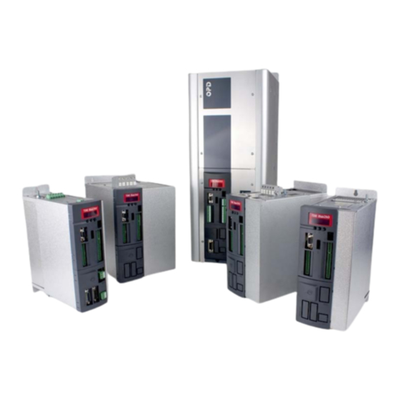
- Page 1 Products Tde Macno Installation OPDE...
- Page 3 Thank you for the trust you have placed in us by vo azionamento “OPDE”. purchasing our new motor drive “OPDE”. Ci auguriamo che il prodotto soddisfi pienamente le We hope that this product meets all your present and Vostre aspettative attuali e future.
- Page 4 GARANZIA WARRANTY 1) Nei limiti di quanto stabilito nella presente garanzia, 1) Within the limits of this Warranty, the undersigned il sottoscritto fabbricante si impegna a riparare tutti Manufacturer undertakes to repair any defects in gli eventuali difetti di costruzione che si manifestino workmanship that may be detected during the durante il periodo di garanzia, fissato in 12 (dodici) warranty period which is 12 (twelve) months from...
- Page 5 3.1- Name of the Device ........pag. 10 3.2- Codifica OPDE ..........3.2.- OPDE Code ..........pag. 10 3.3- Codifica OPDE per applicazioni energie 3.3- OPDE code for energy power applica- alternative..............tions……………………………………………. pag. 11 3.4- Denominazione dei componenti e 3.4- Component Names and Sizes………………...
- Page 6 5.6- Braking ............pag. 78 5.7- Opzioni lato motore ........5.7- Options – Motor Side ........ pag. 79 5.8- Capacità all’interno del drive OPDE... 5.8- Capacity in the OPDE drive……………….. pag. 80 6- SICUREZZA 6- SAFETY 6.1- Direttive e norme di riferimento ....
- Page 7 1.1- MARCATURA CE / TARGA 1.1- CE MARKING / DATA PLATE DATI The CE marking attests that the equipment complies La marcatura CE attesta la conformità dell’apparecchio with the essential safety and health requirements ai requisiti essenziali di sicurezza e di salute previsti provided for in the European Directives referred to in dalle Direttive europee riportate nella dichiarazione CE the CE Declaration of Conformity.
- Page 8 2.1- IMPORTANZA DEL MANUALE 2.1- IMPORTANCE OF THIS MANUAL PRIMA DI UTILIZZARE L’APPARECCHIO IN OGGETTO È PRIOR TO USING THE DEVICE HEREIN, AUTHORIZED OBBLIGATORIO CHE GLI OPERATORI AUTORIZZATI OPERATORS MUST THOROUGHLY READ AND UNDER- LEGGANO E COMPRENDANO IN TUTTE LE SUE PARTI STAND THIS ENTIRE MANUAL.
- Page 9 IN CASO DI SMARRIMENTO O DETERIORAMENTO DEL IF THE MANUAL IS LOST OR DAMAGED, REQUEST A MANUALE RICHIEDERNE COPIA AL FABBRICANTE COPY FROM THE MANUFACTURER, QUOTING THE SPECIFICANDO I DATI DI IDENTIFICAZIONE DELL’AP- DEVICE IDENTIFICATION DATA (CE MARKING / DATA PARECCHIO (V.
- Page 10 OPDE (s. FIG. 2). te all’azionamento OPDE (v. FIG. 2). MP00000B00 V_2.6...
- Page 11 FIG. 2 (Etichetta segnaletica / Warning label) 2.3- ABBREVIATIONS 2.3- ABBREVIAZIONI Some of the abbreviations appearing this manual are Nella TAB. 1 sono elencate alcune abbreviazioni listed in TAB. 1. usate nel manuale. Circa / Approx. Minuti / Minutes ca. / ca. Min / min Capitolo / Section Numero / Number...
- Page 12 OPDE drive 3.2- OPDE CODE 3.2- CODIFICA OPDE Below is a description of the OPDE code, explaining Di seguito viene descritto il codice OPDE nelle singole the meaning of each single letter appearing in the lettere che troviamo nel campo “Type” della marcatura “Type”...
- Page 13 POWER APPLICATIONS ALTERNATIVE Oltre all’OPDE inverter standard è presente la linea di In addition to OPDE standard inverter there is the line inverter OPDE Energy ( brushless, asincrono, ecc..) OPDE Energy (brushless, asynchronous, ext..) for per applicazioni energie alternative. Di seguito viene energy power application.
- Page 14 Esempio codifica OPDE nella versione per motore Example of OPDE code version for 03A brushless mo- brushless a 03A Livello / Level Prodotto / Product OPDE Tipo / Type Brushless / Brushless sensorless Taglia / Size Sovraccarico / Overload Standard 5kHz PWM...
- Page 15 FIG. 3A - 3B - 3C - 3D - 3E - 3F - 3G - 3H - 3I - 3L 3L sono rappresentati e denominati i componenti prin- show the main components that make up an OPDE cipali che costituiscono gli Azionamento OPDE e and OPDE Energy drives with the relevant names and overall sizes, for each model.
- Page 16 Mod. 03A - 07A Mod. 12A - 15A - 22A Mod. 32A VISTA DAL BASSO / BOTTOM VIEW 26,5 26,5 53.5 53.5 75 mm 75 mm 59,5 56,5 89 mm 116 mm 137 mm VISTA ANTERIORE / FRONT VIEW VISTE DALL’ALTO / TOP VIEW FIG.
- Page 17 If a terminal is present, supply at least 5A fornire minimo 5A For special instructions see relevant manual Per indicazione specifiche vedi l’apposito manuale MOD. OPDE Larghezza / Length (mm) Altezza / Height (mm) Profondità / Depth (mm) Viti di fissaggio / Fixing screws Peso / Weight (kg) FIG.
- Page 18 Mod. 40A - 48A - 60A VISTA DAL BASSO / BOTTOM VIEW 132 mm 26,5 26,5 32.5 29.5 VISTA ANTERIORE / FRONT VIEW VISTE DALL’ALTO / TOP VIEW FIG. 3C (Denominazione dei componenti - Dimensioni / Component names - Sizes) MP00000B00 V_2.6...
- Page 19 If a terminal is present, supply at least 5A fornire minimo 5A For special instructions see relevant manual Per indicazione specifiche vedi l’apposito manuale MOD. OPDE Larghezza / Length (mm) Altezza / Height (mm) Profondità / Depth (mm) Viti di fissaggio / Fixing screws Peso / Weight (kg) FIG.
- Page 20 Mod. 70A - 90A - 110A - 150A VISTA DAL BASSO / BOTTOM VIEW 150 mm 150 mm 251 mm VISTA ANTERIORE / FRONT VIEW VISTA DALL’ALTO / TOP VIEW FIG. 3E (Denominazione dei componenti - Dimensioni / Component names - Sizes) MP00000B00 V_2.6...
- Page 21 If a terminal is present, supply at least 5A Se il morsetto è presente (può non essere previsto), fornire mini- For special instructions see relevant manual mo 5A Per indicazione specifiche vedi l’apposito manuale MOD. OPDE 110A 150A Larghezza / Length (mm) Altezza / Height (mm) Profondità...
- Page 22 Mod. - 175A - 220A - 250A FIG. 3G (Denominazione dei componenti - Dimensioni / Component names - Sizes) MP00000B00 V_2.6...
- Page 23 25) Connettore fielbus (opzionale) 25) Fieldbus connector (option) 26) Pannello copertura morsetti di potenza 26) Cover for pawer connections 27) Holes to fix the OPDE 27) Fori di fissaggio 28) Heat sink 28) Alette radiatore per raffreddamento 29) Ground terminal...
- Page 24 Mod. 310A - 370A - 460A FIG. 3I (Denominazione dei componenti - Dimensioni / Component names - Sizes) MP00000B00 V_2.6...
- Page 25 Se il morsetto è presente (può non essere previsto), fornire mini- If a terminal is present, supply at least 5A mo 5A For special instructions see relevant manual Per indicazione specifiche vedi l’apposito manuale MOD. OPDE 310A 370A 460A Altezza / Height (mm) Larghezza / Length (mm) Profondità...
- Page 26 3.5- DATI TECNICI 3.5- TECHNICAL DATA Nelle TAB. 3A - 3B - 3C - 3D sono riportate i dati The technical data of the OPDE drive are illustrated in tecnici che caratterizzano l’azionamento OPDE. TAB. 3A - 3B - 3C - 3D.
- Page 27 Mod. OPDE 110A Modulazione / Modulation Space Vector PWM Frequenza PWM / PWM Frequency 3÷16kHz (default = 5kHz) Fino a N.3 riferimenti analogici programmabili (risoluzione 12 bit) Up to Nr.3 programmable analog references (12 bit resolution) 1 ingressi in frequenza (A / A - B / B) o FREQ. E UP/DOWN Segnali di riferimento / Reference Signals 1 frequency inputs (A / A - B / B) or FREQ.
- Page 28 Mod. OPDE 150A 175A 220A 250A 310A 370A 460A Alimentazione / Power supply Tensione di ingresso (Vi) Vrms 380V -15% ÷ 460 +10% Input Voltage (Vi) Frequenza / Frequency 45 ÷ 65 Tensione D.C. 530 -15% ÷ 650 +10% D.C. Voltage Corrente di ingresso alla potenza nominale (∆V=3%)
- Page 29 Mod. OPDE 150A 175A 220A 250A 310A 370A 460A Modulazione / Modulation Space Vector PWM 3÷16kHz (default = 5kHz da mod. 175A ÷ 370A / 5kHz from mod. 175A ÷ 370A) Frequenza PWM / PWM Frequency (default = 4kHz solo per mod. 150A / 4kHz only for mod. 150A) (default = 3kHz solo per mod.
- Page 30 TAB. 3B and 3D and complying with the regulations on safety and health at the work place in force in the Country where the drive is used. OPDE drive must be installed on a wall capable of ensuring stability in relation to its overall dimensions (see FIG.
- Page 31 3) Using OPDE drive (see User Manual); par. 5.2.2); 3) Utilizzo dell’Azionamento OPDE (v. manuale uten- 4) Switching off OPDE drive by disconnecting the po- te); wer supply and waiting long enough for all power in 4) Spegnimento dell’Azionamento OPDE togliendo the components to be fully discharged.
- Page 32 4.5- MAGAZZINAGGIO 4.5- STORAGE Nel caso in cui l’azionamento OPDE debba rimanere If OPDE drive needs to be stored for a long time, place immagazzinato per diverso tempo, è necessario ripor- it in a safe location, with suitable temperature and hu- lo in un ambiente sicuro, con un adeguato grado di midity conditions and protect it against dust.
- Page 33 1 year, the regeneration of the same can not be perfor- guita alimentando semplicemente l’OPDE, ma è neces- med simply supplying the OPDE, but it is necessary to sario richiedere alla TDE MACNO la procedura operativa require all TDE MACNO the operating procedure to da adottare.
- Page 34 1) Posizionare l’azionamento OPDE mantenendo le clearances around it (see FIG. 5); misure minime di posizionamento (v. FIG. 5) 2) Secure the OPDE drive to the wall by means of 2) Effettuare l’attacco dell’azionamento OPDE, con vi- screws, according to the dimensions shown in FIG.
- Page 35 If needed, provide sufficient air ventilation to remove L’ambiente va eventualmente ventilato con sufficiente quantità d’aria per asportare il calore generato dal con- the heat generated by the converter and by other vertitore e dagli altri componenti. components. Ulteriori apparecchiature vanno montate a distanza Any other equipment should be installed at a sufficient sufficiente dall’azionamento onde evitare che possano distance from the drive, in order to prevent any metal...
- Page 36 5.1.1- OPTIONAL BOARDS 5.1.1- INSTALLAZIONE SCHEDE INSTALLATION OPZIONALI In the drive OPDE are present three slot where is pos- Gli azionamenti OPDE sono dotati di tre slot dove è sible to connect some optional boards. possibile inserire alcune schede di espansione.
- Page 37 Viene di seguito riportata la corretta sequenza per l’in- The figures show how to install the optional boards. serimento delle schede opzionali. FIG. 6 (Installazione schede opzionali in OPDE mod 03A ÷ 60A / Optional board Installation in OPDE mod 03A ÷ 60A) MP00000B00 V_2.6...
- Page 38 FIG. 7 (Installazione schede opzionali in OPDE mod 70A ÷ 460A / Optional board Installation in OPDE mod 70A ÷ 460A) MP00000B00 V_2.6...
- Page 39 THE OPDE DRIVE. LA RETE ELETTRICA DI ALIMENTAZIONE A CUI VIENE COLLEGATO L’AZIONAMENTO OPDE DEVE THE POWER MAINS TO WHICH THE OPDE DRIVE IS SODDISFARE LE CARATTERISTICHE TECNICHE RI- CONNECTED MUST MEET THE TECHNICAL SPECIFI- PORTATE NELLE TAB. 3A/3B E 3C/3D (PAR. 3.4) E CATIONS IN TAB.
- Page 40 FIG. 8 (Collegamenti elettrici / Electrical Connections) MP00000B00 V_2.6...
- Page 41 PWM) (FIG. 9). (*) Solo per modelli non autoalimentati/ Only for not autofeed products (1) Solo per modelli OPDE 03A÷60A con tensione di ingresso AC e DC / Only for models OPDE 03A÷60A with AC and DC input (2) Solo per modelli OPDE 70A÷460A con tensione di ingresso DC e AC /Only for models OPDE 70A÷460A with DC and AC input (3) Nelle taglie 40A, 48A e 60A ,alimentati in DC e senza frenatura, non è...
- Page 42 It is also used to reduce interference from the supply Essa, inoltre, serve a ridurre le interferenze della linea line to the OPDE drive and from the drive to the line. verso l’azionamento OPDE e dall’azionamento alla For the size of the input current limiting choke linea.
- Page 43 5.2.2.1 - UTILIZZO DI INTERRUTTO- 5.2.2.1 – USING DIFFERENTIAL RI DIFFERENZIALI(ELCB) / SWITCHES (ELCB) / RESI- DISPOSITIVO DI CORREN- DUE CURRENT DEVICES TE RESIDUA (RCD) (RCD) Esistono tre tipi comuni di ELBC (Earth Leakage Cir- There are three common types of ELBC (Earth Leakage cuit Braker) / RCD (Residual Current Device): Circuit Breaker) / RCD (Residual Current Device): AC - rileva le correnti di guasto in c.a.
- Page 44 If the interruption za è obbligatorio. Un cortocircuito tra le fasi U, V, W between the motor and the OPDE drive is obtained by causa il blocco del convertitore. In caso di interruzione means of electromagnetic switches (such as contac-...
- Page 45 N.B.: IL TEMPO DI ANTICIPO AL BLOCCO, DELL’AZIO- N.B.: THE BLOCK LEAD TIME FOR THE OPDE DRIVE NAMENTO OPDE, PUÒ ESSERE OTTENUTO CAN BE OBTAINED SIMPLY BY ACTING ON THE SEMPLICEMENTE AGENDO SUL RITARDO DI OPENING DELAY OF ELECTROMECHANICAL APERTURA DEGLI ORGANI ELETTROMECCANI- COMPONENTS;...
- Page 46 TDE porovides an auto-feed version which is particolari richieste, la TDE, ne fornisce una versione recognisable by the C letter (see OPDE codes par.). In autoalimentata, che si riconosce dalla lettera C (vedi this version the +24Vdc is generated by the drive par.
- Page 47 5.2.8- CONNECTION VIA SHARED COMUNE Gli azionamenti OPDE prevedono la possibilità di OPDE drives can be powered by a common bus, essere alimentati attraverso un bus comune, in instead of 3-phase supply mains, by means of a alternativa alla rete trifase, mediante un opportuno suitable DC supply unit or diode bridge (s.
- Page 48 5.2.9- DISPOSIZIONI CONNESSIO- 5.2.9- POWER CONNECTIONS LAY- NI DI POTENZA (RETE, OUT (MAINS, MOTOR) MOTORE) Mod. 03A - 07A L1-L2-L3: ingresso linea U-V-W: uscita motore L1-L2-L3: line input U-V-W: motor output “+” “-”: collegamento in DC Bus “+” “-”: DC Bus connection collegamento “+”...
- Page 49 Mod. 12A - 15A - 22A L1-L2-L3: ingresso linea U-V-W: uscita motore L1-L2-L3: line input U-V-W: motor output “+” “-”: collegamento in DC Bus “+” “-”: DC Bus connection collegamento “+” “F”: resistenza frenatura “+” “F”: Brake resistor con- nection PE: collegamento cavo di terra del motore e scher-...
- Page 50 Mod. 32A - 40A - 48A - 60A L1-L2-L3: ingresso linea U-V-W: uscita motore L1-L2-L3: line input U-V-W: motor output “+” “-”: collegamento in DC Bus “+” “-”: DC Bus connection collegamento “+” “F”: resistenza frenatura “+” “F”: Brake resistor con- nection PE: collegamento cavo...
- Page 51 Mod. 70A - 90A - 110A 150A (AC) con copertura rimossa / without cover L1-L2-L3: ingresso linea U-V-W: uscita motore (fare passare attraverso il toroide presente all’interno, senza schermo e terra) L1-L2-L3: line input U-V-W: motor output (pass through the present toroid inside without, the shield and ground) “+”...
- Page 52 Mod. 70A - 90A - 110A 150A (DC) con copertura rimossa / without cover U-V-W: uscita motore (fare passare attraverso il toroide presente all’interno, senza schermo e terra) U-V-W: motor output (pass through the present toroid inside, without the shield and ground) “+”...
- Page 53 AC + freno / AC + Brake AC senza freno / AC brakeless DC + freno / DC + Brake DC senza freno / DC brakeless L1-L2-L3: ingresso linea - U-V-W: uscita motore “+” “-”: collegamento in DC Bus “+” “F”: collegamento resistenza frenatura “+”...
- Page 54 5.2.10- COLLEGAMENTI LOGICI 5.2.10- LOGIC CONNECTIONS Mod. 03A - 07A - 12A - 15A 22A - 32A - 40A - 48A - 60A VISTA ANTERIORE FRONT VIEW FIG. 12A (Collegamenti logici / Logic connections) MP00000B00 V_2.6...
- Page 55 Mod. 70A - 90A - 110A - 150A - 175A 220A - 250A - 310A - 370 - 460A VISTA ANTERIORE / FRONT VIEW FIG. 12B (Collegamenti logici / Logic connections) MP00000B00 V_2.6...
- Page 56 5.2.11- COLLEGAMENTI LOGICI DI- 5.2.11- DIGITAL AND ANALOG GITALI E ANALOGICI LOGIC CONNECTIONS FUNZIONE DESCRIZIONE / DESCRIPTION FUNCTION L.I.1 Ingressi logici configurabili (v. FIG. 13). Tutti gli ingressi sono optoisolati dalla regolazione interna. L.I.2 L.I.C. è il comune degli ingressi L.I.1, L.I.2, L.I.3, L.I.4. 24Vdc ±10% Imax=10mA Configurable Logic Inputs (see FIG.
- Page 57 FIG. 13 (Ingressi logici configurabili / Configurable logic inputs) FIG. 14 (Ingresso analogico configurabile Configurable analog input) FIG. 15 (Uscite logiche configurabili / Configurable logic output) FIG. 16 (Uscita analogica configurabile Configurable analog output) 5.2.12- INGRESSO IN FREQUENZA 5.2.12- FREQUENCY INPUT FUNZIONE DESCRIZIONE / DESCRIPTION FUNCTION...
- Page 58 STO (l’alimentazione deve essere interrotta da opportuni dispositivi di sicurezza) The voltage + 24V_OUT (+24V±10%), generated within OPDE 70÷460A, is available on terminal X6. The output current is internally limited to a 500mA (protection against exter- nal over-current and short-circuit).
- Page 59 The OPDE 70÷460A generates internally an auxiliary supply of +24V from the main power supply. The control board of OPDE can be fed through X3 with an external +24V: there aren't conflict between the voltage generated internally and auxiliary supply provided exter- nally.
- Page 60 5.2.16- SAFE TORQUE OFF CON- 5.2.16- COLLEGAMENTI SAFE NECTIONS (S.T.O.) (option) TORQUE OFF (S.T.O.) (opzionale) Riferirsi al manuale specifico della serie OPDE per For additional information on S.T.O. configurations pls. ulteriori informazioni sulla configurazione dell’S.T.O. refer to the OPDE series Specific Manual.
- Page 61 5.2.17- A.F.E./STARTER 5.2.17- COLLEGAMENTI SINCRO- SYNCHRONISMS CONNECTIONS NISMI A.F.E./STARTER (opzionale) (option) Riferirsi al manuale installazione della serie OPDE per For additional information on A.F.E. configurations pls. ulteriori informazioni sulla configurazione dell’A.F.E. refer to the OPDE series Installation Manual. FUNZIONE DESCRIZIONE/DESCRIPTION...
- Page 62 Il morsetto X8 serve solo per l’alimentazione dei venti- X8 is only the power supply connector of the fans. latori (+24Vdc). The connector X7 is used to enable the fans, so is Il morsetto X7 serve ad abilitare le ventole, per cui è necessary to connected +24Vdc between terminal 3 necessario collegarci una tensione di +24V tra il mor- and 4.
- Page 63 5.2.20- CONFIGURAZIONE DI 5.2.20- DEFAULT I/O CONFIGURA- DEFAULT I/O TION Riferirsi al manuale utente della serie OPDE per ulte- For additional information on I/O configurations pls. riori informazioni sulla configurazione degli I/O. refer to the OPDE series User Manual. INGRESSO / INPUT...
- Page 64 5.2.21 - GESTIONE SCELTA 5.2.21 - MANAGEMENT CHOICE OF INGRESSI ANALOGICI ANALOG INPUTS FIG. 18 (Gestione scelta ingressi analogici / Management choise of analof inputs) Configurazione di default/ Default configuration DIP 1 -> A.I.1 Analog input 1 DIP 1 -> A.I.1 Ingresso analogico 1 DIP 2 ->...
- Page 65 5.3 – COLLEGAMENTO SCHEDE 5.3 – OPTIONAL BOARDS OPZIONALI CONNECTION Vengono di seguito riportati i collegamenti per la sche- In the follow paragraph is described how to connect de di retroazione: the optional boards: 5.3.1 – TTL ENCODER 5.3.1 – TTL ENCODER -Cablare connettore femmina 15 vie -Cabling 15-way connector female 8 + 5V...
- Page 66 5.3.2 – RESOLVER 5.3.2 – RESOLVER -Cablare connettore maschio 15 vie -Cabling 15-way connector male 3 REF 4 0REF 5 0COS 0SIN 0SP6 0SP6 SHIELD SHIELD COLLEGAMENTI CAVO DRIVE/MOTORE DRIVE/MOTOR CABLE CONNECTIONS Red-White Yellow/White or Black/White Black Yellow Blue Esempio di codice colori del resolver/ Example of Resolver colors code Usare solo cavo a doppini intrecciati e schermati sin- Only use 4-couples twisted and shielded couple cable golarmente più...
- Page 67 5.3.3 – ENCODER E SENSORE DI 5.3.3 – ENCODER AND HALL HALL SENSORS -Cablare connettore femmina 15 vie -Cabling 15-way connector female + 5V + 5V SONDA_C SONDA_C / SONDA_C / SONDA_C SONDA_A SONDA_A / SONDA_A / SONDA_A SONDA_B SONDA_B / SONDA_B / SONDA_B / PC1...
- Page 68 5.3.4 – SIN COS ENCODER INCRE- 5.3.4 – INCREMENTAL SIN COS MENTALE ENCODER -Cablare connettore femmina 15 vie -Cabling 15-way connector female + 5V + 5V R+(TOP0) R+(TOP0) R-(TOP0) R-(TOP0) SHIELD SHIELD COLLEGAMENTI CAVO DRIVE/MOTORE DRIVE/MOTOR CABLE CONNECTIONS Usare solo cavo a doppini intrecciati e schermati sin- Only use 4-couples twisted and shielded couple cable golarmente più...
- Page 69 5.3.6 – ENDAT 2.1 5.3.6 – ENDAT 2.1 -Cablare connettore femmina 15 vie -Cabling 15-way connector female COLLEGAMENTI CAVO DRIVE/MOTORE MOTOR/DRIVE CABLE CONNECTIONS - Only use 4-couples twisted and shielded couple cable - Usare solo cavo a doppini intrecciati e schermati with external shield.
- Page 70 5.3.8 – RESOLVER ALTA RISOL- 5.3.8 – HIGH RESOLUTION RE- UZIONE (RDC) SOLVER (RDC) -Cablare connettore maschio 15 vie -Cabling 15-way connector male 3 REF 4 0REF 5 0COS 0SIN 0SP6 0SP6 SHIELD SHIELD COLLEGAMENTI CAVO DRIVE/MOTORE MOTOR/DRIVE CABLE CONNECTIONS Red-White Yellow/White or Black/White Black...
- Page 71 5.3.9 – HIPERFACE 5.3.9 – HIPERFACE -Cablare connettore maschio 15 vie -Cabling 15-way connector male COLLEGAMENTI CAVO DRIVE/MOTORE MOTOR/DRIVE CABLE CONNECTIONS La tensione di alimentazione del sensore (+US) viene The supply voltage of the sensor (+US) is internally generata internamente dal drive (circa 9V). generated by the drive (about 9V).
- Page 72 5.3.11 – ACTIVE FRONT END (A.F.E) (A.F.E) cod. 274S001620VV TDE MACNO connected and set this optional board , Questa scheda opzionale viene collegata e settata da depending on model and size requested by the costu- TDE MACNO, secondo modello e taglia richiesti dal...
- Page 73 5.3.12 – CAN BUS 5.3.12 – CAN BUS In the follow is indicated the pin signals position about Viene di seguito riportata la piedinatura della scheda CAN BUS optional card opzionale per la comunicazione via CAN BUS DIPSWITCH CAN H BUS 2 TERM (principale)/...
- Page 74 5.3.13 – PROFIBUS 5.3.13 – PROFIBUS Viene di seguito riportata la piedinatura della scheda In the follow is indicated the pin signals position about opzionale per la comunicazione via PROFIBUS - CAN PROFIBUS - CAN BUS optional card 5) GNDISO 4) DE 8) A 3) B...
- Page 75 TIA. CAT5e cable runs are limited to a maximum rec- massima raccomandata è 100m. ommended run length of 100m. Anche TDE MACNO raccomanda cavi schermati per Also TDE MACNO recommends shielded cables for ambienti dove, la vicinanza al cavo di alimentazione,...
- Page 76 5.3.15 – ANYBUS 5.3.15 – ANYBUS Alloggio ANYBUS su 22A/32A, vedi ma- nuale installazione per tutte le taglie. ANYBUS accommo- dation for 22A/32A, see installation ma- nual for all sizes. Esempio moduli ANYBUS / ANYBUS example Tutti i nostri drive hanno la possibilità di ospitare i mo- All our drives have the possibilty to accommodate the duli ANYBUS in commercio, le taglie a libro su un lato, commercialy ANYBUS modules, the folding sizes on...
- Page 77 SERIALE RS422/485 SERIAL CONNECTION La linea seriale presente sugli azionamenti OPDE The serial line present on OPDE drives has connection prevede il collegamento per la trasmissione dei dati a capability for “4-wire” data transmission and therefore it “4 fili” e per questo ha la possibilità di comunicare in can communicate in full-duplex mode.
- Page 78 Minima induttanza / Minimum Inductance Induttanza Corrente Corrente di saturazione Codice della Mod. minima (mH) termica (A) di picco (A) Codice TDE Macno induttanza di linea Minimum Thermal Peak Saturation TDE Macno Code Line Choke Code Inductance (mH) Current (A) Current (A) 5.84...
- Page 79 CARATTERISTICHE MINIME E MASSIME DEI FUSIBILI PER LA LINEA DI INGRESSO / MINIMUM AND MAXIMUM FEATURES OF INPUT FUSES Tensione (AC) I2 T massimo (A2s) per Fusibili / Fuses (A) Voltage (AC) ingresso AC OPDE I2 T maximum (A2s) for AC input 5-16 (10-16) 10-16 (16) 16-25 (25-32) 1200 20-32 (32-40)
- Page 80 TAB. 18 (Frenatura / Braking) (4) Per le taglie superiori a 60 A i valori delle resistenze di frenatura fornite da TDE Macno garantiscono il corretto funzionamento del con- vertitore per sovraccarichi massimi pari al 150% / For sizes above 60 A the values of the braking resistors supplied by TDE Manco ensure the proper operation of the drive for maximum overload 150% ATTENZIONE / ATTENTION: I valori delle resistenze di frenatura si riferiscono ad applicazioni in cui la tensione di rete è...
- Page 81 Induttanza da abbinare ad un inverter che controlla solo un motore, in caso di più motori controllati da un solo inverter, contat- tare TDE MACNO. / Choke to match with an only motor, in case there are more motors controlled by one inverter, contact TDE MACNO.
- Page 82 3000 uF 3600 uF 4200 uF 110A 4800 uF 150A 9400 uF 175A 9400 uF 220A 13600 uF 250A 11750 uF 310A 14100 uF 370A 20400 uF 460A TAB. 27 (Capacità all’interno del drive OPDE/Capacity in the OPDE drive) MP00000B00 V_2.6...
- Page 83 6.1- DIRETTIVE E NORME DI 6.1- REFERENCE DIRECTIVES AND RIFERIMENTO STANDARDS L’azionamento in oggetto è stata progettata e realizza- The drive referred to herein has been designed and ta tenendo presente lo stato attuale della tecnica, gli manufactured keeping in mind the considerations that obiettivi prefissati dai requisiti essenziali di sicurezza e emerged from a view to fulfilling the essential safety and health requirements as set forth in the European...
- Page 84 6.2- SCELTA DI FUSIBILI, 6.2- SELECTING FUSES, INPUT INDUTTANZA DI INGRESSO, CHOKE & BRAKING RESISTENZE DI FRENATURA RESISTORS La scelta delle sezioni dei conduttori e dei fusibili è The selection of the conductors’ cross-sections and si- stata fatta secondo le norme CEI EN 60204-1, ze of fuses has been made according to CEI EN materiale per conduttori rame, classe di installazione 60204-1, for copper conductors, installation class B1.
- Page 85 6.3- ACCORGIMENTI 6.3- INTERFERENCE - SUPPRES- ANTIDISTURBO SION MEASURES Electric or electronic devices can interfere as a re- Apparecchiature elettriche od elettroniche possono sult of network connections or other metal connec- influenzarsi reciprocamente a causa dei collega- tions. menti di rete od altre connessioni metalliche fra di In order to reduce or eliminate interference, the dri- loro.
- Page 86 ed altri commutatori elettromeccanici che fossero 8) Make all external control, measurement and installati nello stesso armadio del convertitore, regulation connections by means of shielded montati direttamente sui collegamenti delle bobine cables. stesse. 9) Cables that can propagate interferences should be laid separately and at a distance from the 8) Eseguire tutti i collegamenti di controllo, misurazio- ne e regolazione esterni con cavi schermati.
- Page 87 6.4-COLLEGAMENTO/FISSAGGIO 6.4- CONNECTION/FIXING OF DELLE SCHERMATURE PER OPDE SHIELDS ON OPDE Connect all the related cable shields to the sensors, to Collegare tutti i relativi cavi schermati ai sensori, alle the feedbacks, fieldbus, references (analog and fre- retroazioni, ai bus di campo, ai riferimenti (analogici e quency) and power to the bracket as shown on image di frequenza) e l’alimentazione alla staffa, come mo-...
- Page 90 s.p.a. tecnologie digitali elettroniche Via dell’Oreficeria, 41 36100 Vicenza - Italy Tel +39 0444 343555 Fax +39 0444 343509 www.tdemacno.com...