
Related Manuals for TDE MACNO MINIOPD EXP

Summary of Contents for TDE MACNO MINIOPD EXP
- Page 1 MINIOPD EXP - OPD EXP MINIOPD EXP - OPD EXP USER’S MANUAL - ASYNCHRONOUS USER’S MANUAL - ASYNCHRONOUS Tecnologie Digitali Elettroniche S.p.A.
-
Page 3: Table Of Contents
SOMMARY Introduction ..................... 5 Parameters (P) ........................5 Connections (C) ........................5 Input logic functions (I) ......................6 Internal values (D) ........................6 Output logic functions (o) ......................6 ... - Page 4 3.3.2 PID controller ........................ 73 Fieldbus ....................76 MODBUS parameters ......................76 4.1.1 Application Configuration ....................76 4.1.2 Managed services ......................77 Can open..........................80 4.2.1 Configuration of the application ..................80 ...
-
Page 5: Introduction
Reserved parameters (blu text in OPDExplorer): may be changed only at a standstill after having opened the reserved parameter key in P60 or the TDE MACNO reserved parameters key in P99; TDE MACNO reserved parameters (violet text in OPDExplorer): may be changed only at a standstill after having opened the TDE MACNO reserved parameters key in P99. -
Page 6: Input Logic Functions (I)
They are split up into free, reserved and TDE MACNO reserved connections, and are changed in the same way as the parameters. The internal representation base is always as whole number 1.3 INPUT LOGIC FUNCTIONS (I) The input logic functions are 32 commands that come from configured terminal board logic inputs, from the serial line, and from the fieldbus. -
Page 7: Asynchronous Parameters
2 ASYNCHRONOUS PARAMETERS The “Asyncrhonous Parameters” are used to control the current or speed of a feedback vector induction motor. The speed and current reference values are generated by the application. See the application parameters for further information. As an absolute position value is not required for the sensors (managed with an optional internal electronic board) incremental TTL Encoders and incremental Sin/Cos Encoders may be used. -
Page 8: Motor Plate
2.1.1.1 DRIVE CURRENT OVERLOAD SELECTION Four types of drive overload can be set on C56 Overload type for rated drive current (P53) 120% for 30 seconds 150% for 30 seconds 200% for 30 seconds 200% for 3 seconds and 155% for 30 seconds NB: the choice also changes the rated drive current as shown by the tables in the installation file and the correct value is always displayed in ampere rms in P53. -
Page 9: Motor Sensor
Name Description Default Scale P65 - Max. operating MOT_SPD_MAX 60000 2000 speed (n MAX) P66 - Nominal power MOT_COS_PHI 0.500 1.000 0.894 1000 factor P67 - Number of motor MOT_POLE_NUM poles P70 - Motor thermal PRC_MOT_I_THERM 10.0 110.0 % PRC_MOT_I_NOM current P71 - Motor thermal time MOT_TF_THERM... - Page 10 Scal Name Description Default Range Encoder SENSOR_SEL C00 - Speed sensor Resolver Resolver RDC Sin/Cos incr P68 - Number of absolute sensor RES_POLE poles P69 - Number of encoder ENC_PPR 60000 1024 pulses/rev pulses/revolution C74 - Enable incremental encoder EN_TIME_DEC_ENC time decode P89 - Tracking loop bandwidth RES_TRACK_LOOP_BW...
-
Page 11: Autotuning Control And Motor Measured Model
2.1.3.1 FINE SETUP MOTOR SENSOR For some kind of sensor, after the auto tuning procedure is possible set some sensor parameter to increase the performance. 2.1.3.1.1 FINE SETUP FOR RESOLVER The fine tuning resolver setup allows to set, with a semiautomatic procedure, any offset and a multiplicative factor to adjust the signals acquired by the resolver channels in order to increase system performance. - Page 12 Name Description Default Scale C41 - Enable sensor and EN_TEST_CONN motor phase tests P114 - Current in PRC_I_TEST_CONN connection tests for UVW, 100.0 % DRV_I_NOM 327.67 Poles and reading Rs Range EN_AUTOTUNING C42 - Enable auto-tunings Test 1 and 2 Test 3 and 4 C75 - Disable Autotuning DIS_DEF_START_AUTO...
- Page 13 SPD_RIF=TEST_SPD_ MAX (P132) T_RIF=TEST_SPD_T_MAX (P130) time T_RIF= - TEST_SPD_T_MAX (P130) Otherwise: T_RIF=TEST_SPD_T_MAX (P130) time T_RIF= - TEST_SPD_T_MAX (P130) User’s manual...
- Page 14 2.1.4.2 STEP RESPONSE Step response is a common mode to test speed loop stability and dynamic performance. For enable this test set C53=2 (EN_TEST_SPD = 2 Step). In the display appears “Auto”. At this point all speed reference are ignored, instead a fixed speed reference is calculated equals to maximum test torque (P130) divided by speed regulator proportional gain.
- Page 15 Name Description Default Scale PRC_MOT_T_MAX P41 - Maximum torque at full load 400.0 400.0 % MOT_T_NOM 40.96 MOT_COS_PHI P66 - Nominal power factor 0.500 1.000 0.894 1000 PRC_MOT_I_T_NOM P72 - Nominal torque current 100.0 95.2 % PRC_MOT_I_NOM 327.67 PRC_MOT_I_FLX_NOM P73 - Nominal flux current 100.0 30.2 % PRC_MOT_I_NOM...
- Page 16 After setting the drive to STOP and opening the reserved parameter key (P60=95), set C41=1 to enable the test. To start the test enable RUN command with its digital input. Once the test has started the motor will rotate in the positive direction at low speed and all Encoder edges are counted.
- Page 17 After setting the drive to STOP and opening the reserved parameter key (P60=95), set C41=1 to enable the test. To start the test enable RUN command. Once the test has started the motor will rotate in the positive direction at low speed and some measure are done on Resolver signals.
- Page 18 it starts the second test: P79=0 : meaning that is missing at least one Encoder channel, therefore A14 code 0 is triggered P79<0 : meaning that Encoder channels are exchanged, therefore A14 code 0 is triggered P79>0 : everything is ok In the second part is checked the Encoder pulses reading, well known from P69 parameter the number of edges in a mechanical turn (P69x4, because are counted both two channels edge).
-
Page 19: Identifying Models Of Induction Motor
If A14 code=0 is enabled, connections U,V,W do not match the internal phases of the drive. Invert two phases and repeat the test. If A15 code=3 is enabled, the values set do not comply with the motor pole and sensor settings. At the end of the test, check parameter P79 as it may give some indication as to the problem. - Page 20 is enabled with connection C42: this test must be carried out with the motor decoupled from the load. Failure to do so may invalidate the results. If the tests cannot be carried out for any reason, these values will have to estimated by reading the motor plate and following these points: •...
- Page 21 The tests may be halted at any moment by disabling RUN the drive will trigger an alarm (A7) but any results will be saved. Once C42 ≠ 0 has been set again, if C75=0 the default values of the parameters being tested will be automatically reloaded, on the contrary if C75=1 remain active actual data.
- Page 22 φ φ / φ 45,0 55,0 65,0 75,0 82,0 88,0 93,0 97,0 100,0 102,0 The term K φ is equal to: Id Iφ Φ Φ i.e. it is the coefficient that when multiplied by the normalized flux in relation to the rated flux gives the normalized flux current in relation to the magnetizing current.
-
Page 23: Motor Control
Name Description PRC_MOT_T_MAX P41 - Maximum torque at full load T_ROTOR P74 - Rotor time constant Tr T_STATOR P75 - Stator time constant Ts MOT_T_NOM P78 - Nominal motor torque V_REG_KP P80 - Kpi voltage regulator proportional gain V_REG_TF P82 - Tfi voltage regulator (filter) time constant I_REG_TI P84 - Tic current regulator lead time constant I_REG_TF... -
Page 24: Acceleratio Ramps And Speed Limit
Regulation controls speed by default; here the application manages the speed reference values, and the torque request is used as a reference value added to the speed regulator output (feed-forward). Note that it is a torque control and not a current control, consequently during flux weakening the control automatically generates the request for the active current needed to obtain the required torque. - Page 25 In the standard application, by default (P236=1), the speed reference value passes across a ramp circuit that graduates its variations before it is used. Parameters P21, P22, P23 and P24 can be used to establish independent acceleration and deceleration slopes in both directions of movement, establishing the time required to pass from 0 to 100% in seconds.
-
Page 26: Speed Control
In a transitional phase however the system passes through all of the band’s frequencies (ramp). The use or otherwise of the exclusion bands requires the setting of the corresponding connection C38: Band 1 (P179-P180) C81=0 (Default) not excluded, C81=1 excluded Band 2 (P181-P182) C81<2 not excluded, C81=2 excluded For example if the working fmax = 50Hz and the plant presents two resonance frequencies which are quite clear at 45Hz and 35Hz the frequencies between 43 - 47 Hz and 33 - 37 Hz could be excluded... - Page 27 2.2.2.1 MANAGING SPEED REFERENCE VALUES The application generates two speed reference values: One , sysSpeedReference, is a percentage of the maximum speed (set in parameter P65) displayed in internal value d33 and on monitor o41. The other, sysSpeedRefPulses is electrical pulses for a period of PWM. This particular reference is used so as not to be lose any pulses if the frequency input is used.
- Page 28 I° II° -40dB/dec Useful area for 2nd order filter -20dB/dec By taking as reference the 1st order filter time constant tolerated by the system, the 2 order filter has to be set to double frequency (half time) so that it has the same phase margin. The effects of the 2nd order filter will be better than the 1st order filter only when the frequency is double that of the 2nd order filter.
-
Page 29: Torque And Current Limits
The Startup time is the time necessary for motor and load to reach the maximum speed (set in P65) with the nominal motor torque. This data has to be set in milliseconds in parameter P169. It’s useful to set some milliseconds of filter (P168) on order to avoid too much noise on torque reference for the time derivative. - Page 30 sysMaxPositiveTorque sysMaxTorque Maximum torque CW Maximum motor Φ torque Φnom Maximum torque set by current limit Φ Vbus Φnom regulator C34=1 Vbus_rif C34=1 Mns off Maximum torque CCW 1P23 V controller brake sysMaxNegativeTorque 2.2.3.2 MAXIMUM MOTOR TORQUE LIMIT The induction motor has a maximum torque that depends on its construction characteristics. The graph below illustrates the progress of a torque curve according to speed with the motor powered by a constant frequency (Ns).
- Page 31 It is proved that the maximum motor torque decreases during flux weakening in proportion to the square of the φ / φ nom ratio. Thus the motor has three working areas: Constant torque: the maximum torque is available up to the rated speed (as long as the current to deliver it is available);...
-
Page 32: Current Control
(Ta = Ti*Kp); and P85, filter constant in ms. Parameters P83 and P84 cannot be changed directly because they are considered to be perfectly calculated by the auto-tuning. P83 can only be changed by accessing TDE MACNO reserved parameter P126 “Multiplication coefficient Kp and current loop”... -
Page 33: Voltage/Flux Control
2.2.5 VOLTAGE/FLUX CONTROL Name Description Default Scale PRC_FLX_REF P35 - Flux Reference 120.0 % MOT_FLX_NOM 40.96 P36 - Kv Max operating voltage V_REF_COEFF 100.0 327.67 multiply factor PRC_FLX_MIN P52 - Minimum Flux admitted 100.0 % MOT_FLX_NOM 40.96 P80 - Kpi voltage regulator V_REG_KP 100.0 proportional gain... - Page 34 Parameters P80 and P81 cannot be changed directly because they are considered to be perfectly calculated by the auto-tuning. They can only be changed by accessing TDE MACNO reserved parameter P127 “Multiplication coefficient Kp and Ta flux loop” The voltage/flux regulator limit is normally set at ± rated motor current so that the total flux may be changed quickly during the transient state.
-
Page 35: Protection
2.2.5.2 WAIT FOR MOTOR DEMAGNETIZING When the drive is switched off it is dangerous to switch on immediately, due to the unknown magnetic flux position that could produce a motor over–current. The only chance it’s to wait the time needed for the magnetic flux to reduce itself with its time constant that depend on the motor type and can vary from few milliseconds to hundreds of milliseconds. - Page 36 2.3.1.1 POWER SOFT START The bridge rectifier build in the drive may be uncontrolled (diode) or semi-controlled (up to OPEN 40 it is uncontrolled). If the diode bridge is implemented, the power soft start function acts bypassing a soft start resistor (in series with the output of the power bridge), after the DC Bus Voltage has charged;...
- Page 37 2.3.1.2.1 CONTINUING TO WORK (C34=0; DEFAULT) This operating procedure is adapted to those applications in which it is fundamental to have unchanged working conditions in each situation. Setting C34=0 the drive, even if the mains supply voltage is no longer available, continues to work as though nothing has been modified over the control, pulling the energy from the present capacitor to the inner drive.
- Page 38 DC bus voltage 540V speed Minimum voltage 400V allowed (P106) C34=1 Recovery of Kinetic Energy Return Break time mains mains If the alarm condition starts, there is the possibility to enable, setting C35=1 the alarms to an automatic reset at the mains restore 2.3.1.2.3 OVERCOMING MAINS BREAKS OF A FEW SECONDS WITH FLYING RESTART (C34=2)
- Page 39 At the return of the mains, it will need to wait for the time of soft start for the gradual recharging of capacitors for the motor to be able to resume. 2.3.1.2.4 EMERGENCY BRAKE (C34=3) This particular control is adapted to those applications in which the machine may be stopped with an emergency brake in case of mains breaks.
- Page 40 The use of an AC/DC AFE permits a controlled voltage level of the intermediate power (DC Bus) and raises to best control the motors winded to a voltage close to the line voltage. The drive’s dynamic behavior results in a way that optimizes the work as motor or generator. There is a possibility to connect more than one drive to the DC Bus, with the advantage of energy exchange between drives in case of contemporary movements and only one energy exchange with the mains.
- Page 41 2.3.1.3.3 KINETIC ENERGY DISSIPATION ON BREAKING RESISTANCE The standard solution for the OPEN drive is the dissipation of kinetic Energy on braking resistor. All the OPEN drives are equipped with an eternal braking circuit, while the braking resistor must be connected externally, with the appropriate precautions.
-
Page 42: Thermal Protection
2.3.2 THERMAL PROTECTION Name Description Default Scale Range C46 - Enable motor thermal MOT_THERM_PRB_SEL probe management (PTC/NTC) KTY84-130 P91 - Maximum motor MOT_TEMP_MAX temperature (if read with 150.0 °C PT100) C57 - Enable radiator heat DRV_THERM_PRB_SEL probe management (PTC/NTC) P95 - Motor NTC or PTC MOT_PRB_RES_THR 19999 1500... - Page 43 Internal value d28 and analog output 28 display a second-by-second reading of the motor thermal current as a percentage of the rated motor current. When 100% is reached, the motor thermal switch cuts in. P96 can be set with an alarm threshold which, when breached, commutes logic output o.L.14 to a high level indicating the approximation to the motor thermal limit.
-
Page 44: V/F Control
2.4 V/F CONTROL Name Description Default Scale EN_VF_CNTL C80 - Enable V/f control P170 - Slip motor PRC_VF_SLIP_CMP 400.0 40.96 compensation PRC_MOT_F_MAX P171 - Slip compensation VF_TF_SLIP_CMP 150.0 35.0 factor filter P172 - Stator voltage drop PRC_VF_BOOST 400.0 70.0 40.96 compensation PRC_DELTA_VRS VF_EN_DCJ... -
Page 45: Manual Setting Of Working Voltage/Frequency Characteristic
it’s no useful in that application where it’s necessary to produce torque in steady state at frequency below 1Hz (in this case we recommend to use a motor with feedback and a Vector control). To enable the voltage-frequency control set C80=characteristic The most easier way to set the voltage-frequency characteristic is to use the automatic procedure. - Page 46 Points P176 and P178 define the frequency percentage with reference to the maximum working frequency while points P175 and P177 define the percentage voltage with reference to the maximum working voltage (P64). The following curve should clarify the explanation. "TYPICAL CURVE WITH QUADRATIC TORQUE LOAD" If a number of points which is less than two is sufficient to define the curve just program at 0 the frequencies of the points which are not used (P176 and/or P178), so that they will not be considered in the interpolation.
-
Page 47: Load Effect Compensation
As an example we calculate the settings of the parameters in the case of a motor with a rated voltage of 380 Volts and a frequency of 50 Hz, which we want to work at full flux up to 50 Hz and a constant voltage from 50 Hz to 75 Hz. -
Page 48: Particular Control Functions
2.4.4 PARTICULAR CONTROL FUNCTIONS 2.4.4.1 MOTOR FLYING RESTART Since the driver has a maximum current limit it can always be started running with no problems even if the motor is already moving, for example, by inertia or dragged by part of the load. In that event, on starting up, given that normally the frequency reference starts from values close to zero to gradually rise with the ramp times to the working value, the motor is first subjected to a sudden deceleration, within the limit, to then hook onto the reference and follow it with the ramp;... -
Page 49: Standard Application
3 STANDARD APPLICATION 3.1 INPUT 3.1.1 ANALOG REFERENCE Name Description Default Scale P01 - Corrective factor for KP_AI1 -400.0 400.0 analog reference 1 (AUX1) P02 - Corrective offset for OFFSET_AI1 -100.0 100.0 163.84 analog reference 1 (AUX1) D42 - Analog Input AI1 -100 163.84 P200 - Enable analog... - Page 50 D68 - Analog Torque PRC_T_REF_AN -400 % MOT_T_NOM 40.96 reference from Application D10 - Torque reference value PRC_APP_T_REF -100 % MOT_T_NOM 40.96 (application generated) D70 - Analog Torque Max PRC_T_MAX_AN_POS -400 % MOT_T_NOM 40.96 from Application D32 - Maximum torque PRC_APP_T_MAX imposed (application -100...
- Page 51 User’s manual...
- Page 52 It’s possible to enable separately all references using connections or logic input functions. For speed and torque references the active reference is the sum of all enabled references, for torque limit prevails the more constrain active reference, between the sum of analog and the Fieldbus references There can be up to 3 differential analog inputs (A.I.1 ÷...
-
Page 53: Digital Speed Reference
As said above, the enabling of each analog input is independent and can be set permanently by using the corresponding connection or can be controlled by a logic input after it has been suitably configured. For example to enable input A.I.1 the connection P200 or the input logic function I03 can be used, with the default allocated to logic input 3. - Page 54 3.1.2.1 DIGITAL SPEED REFERENCE (JOG) The value programmed in parameter P211 can be used as digital speed reference either by activating the logic function “Enable Jog” I.05 assigned to an input (default input L.I.5) or with the connection P212=1. The resolution is 1/10000 of the maximum working speed. 3.1.2.2 DIGITAL POTENTIOMETER SPEED REFERENCE A function that makes it possible to obtain a terminal board adjustable speed reference through the...
-
Page 55: Frequency Speed Reference
H = active x = does not matter L = not active L -> H = From Off-line to On-line The digital potentiometer reference requires, to be enabled, activation of function I06 after allocating an input or activating connection P218 (P218=1) . In the parameters P215 and P216 the maximum and the minimum admitted reference values can be marked for the digital potentiometer reference. - Page 57 3.1.3.1 SPEED FREQUENCY REFERENCE MANAGEMENT This speed reference in pulses can be provided in 4 different ways (alternatives to each other), that can be selected by means of connection C09. Description Mode of working Analog reference ±10V (optional) Analogic Digital encoder 4 track frequency reference (default) Digital f/s Frequency reference (freq.
- Page 58 Master Slave N° of pulses/revolution = 512 N° of pulses/revolution = 512 P65 = 2500 rpm P65 = 2500 rpm P221 = 50 P222 = 100 The slave goes at the half speed as the master Master Slave N° of pulses/revolution = 512 N°...
- Page 59 3.1.3.3.1 PULSES REFERENCE (P224=0) sysSpeedPercRef Selector Multiply FRQ_IN_NUM(P221) Input Division Selector Encod BASE FRQ IN DEN (P222) FRQ_IN_PPR_SEL sysSpeedRefPuls Selector FRQ_IN_SEL (C09) (P220) ID_EN_FRQ_REF (I19) EN FRQ REF (P223) In this mode, the speed reference is given only in pulses ensuring maximum correspondence master- slave, but with a strong granular signal especially for low frequency input.
- Page 60 3.1.3.3.3 PULSES AND DECODED IN TIME REFERENCE (P224=2) Selecto Multiply FRQ_IN_NUM(P221) Input Divisio Selecto Encod BASE FRQ IN DEN (P222) FRQ_IN_PPR_SE Selector FRQ_IN_SEL (C09) ID_EN_FRQ_REF (I19) EN FRQ REF (P223) Time_Dec Filter 1° order Multipl TimeF TF_TIME_DEC_FRQ sysSpeedPercR (P225) KP TIME DEC FRQ(P2 Ramps bl d sysSpeedRefPul...
-
Page 61: Digital Inputs Configurations
3.1.4 DIGITAL INPUTS CONFIGURATIONS The control requires up to 8 optically insulated digital inputs (L.I.1 … L.I.8.) whose logic functions can be configured by means of connection C1 ÷ C8. The following table shows the logic functions managed by standard application: DEFAULT DEFAULT NAME... -
Page 62: Second Sensor
NB: pay particular attention to the fact that it is absolutely not possible to assign the same logic function to two different logic inputs: after changing the connection value that sets a determined input, check that the value has been accepted, if not check that another has not already been allocated to that input. -
Page 63: Output
Name Description Default Scale OFFSET_SIN_SENS2 P08 - Second sensor sine offset -16383 16383 OFFSET_COS_SENS2 P09 - Second sensor cosine offset -16383 16383 HW_SENSOR2 D62 - Sensor2 presence SENS2_SPD D51 - Second sensor rotation speed D52 - Second sensor Absolute mechanical 1638 SENS2_TURN_POS position (on current revolution) -
Page 64: Analog Outputs Configurations
If you wish to have the logic outputs active at the low level (L) you need just configure the connection corresponding to the chosen logic function but with the value denied: for example, if you want to associate the function “ end of ramp ” to logic output 1 active low, you have to program connection 10 with the number -6 ( C10=-6 ). - Page 65 DEFAULT OUTPUT LOGIC FUNCTIONS OUTPUT Actual mechanical position read by sensor[100%=180] Actual electrical position read by sensor(delta m) [100%=180] Reference speed value before ramps [% n mAX] Reference speed value after ramps [% n MAX] Rotation speed (filtered Tf= 8 TPWM, 1.6ms at 5KHz) [% n MAX] A.0.2 Torque request [% C NOM MOT] Internal value: status (MONITOR only)
- Page 66 Overlapped space loop reference value from application ("sysPosRefPulses")[Pulses per TPWM] Amplitude to the square of sine and cosine feedback signals [1=100%] Sen_theta (Direct resolver and Sin/Cos Encoder) [Max amplitude = 200%] Cos_ theta (Direct resolver and Sin/Cos Encoder) [Max amplitude = 200%] Rotation speed not filtered [% n MAX] Delta pulses read in PWM period in frequency input [Pulses per PWM] Overlapped space loop memory lsw [Electrical pulses (x P67)
-
Page 67: Frequency Output
3.2.3 FREQUENCY OUTPUT Name Description Default Scale ENC_OUT_ZERO_TOP C49 - TOP zero phase for simulated encoder ENC_OUT_DIR C50 - Invert channel B simulated encoder ENC_OUT_PPR_SEL C51 - Choose pulses ev. simulated encoder ENC_OUT_SEL C52 - Simulated encoder selection OPD_ENC_OUT_SEL C54 - Incremental/absolute Simulated Encoder P124 - Simulated encoder Kv gain PRC_ENC_OUT_LOOP 100.0... - Page 68 The simulated encoder outputs are all driven by a “LINE DRIVER”. Their level in the standard drive version is referred to +5V and then it is connected to the internal supply (TTL +5V). In option (to be requested in the ordering) there is the possibility to refer the signal level to an external supply whose value must be between +5V and +24V, connection on terminal 5 and 6.
- Page 69 WARNING: The choice of the number of pulses for revolution depends on the maximum speed and the number of sensor polar couples (P68/2). In the following table are reported this limitation. If it is selected a number of pulses too high compared with the maximum speed it is triggered the alarm A15 code =1.
- Page 70 Displacement +0° +90° +180° +270° The default value is 0. These electrical degrees correspond to the mechanical degrees if the resolver has two poles . Connection C50 inverts the encoder B channel, thus inverting its phase with respect to channel A, with the same motor rotation direction.
-
Page 71: Motion Control
3.3 MOTION CONTROL 3.3.1 INCREMENTAL POSITION LOOP Name Description Default Scale P37 - Maximum tracking error (less significative FLW_ERR_MAX_LSW -32767 32767 32767 part) POS_REG_KP P38 - Kv position loop proportional gain 100.0 P39 - Maximum tracking error (less significative FLW_ERR_MAX_MSW 32767 part) EN_POS_REG... - Page 72 Selector sysPosRefPuls Multiply FRQ_IN_NUM(P221) Input Division Selector Encod BASE FRQ IN DEN (P222) FRQ_IN_PPR_SEL Selector FRQ_IN_SEL (C09) (P220) ID_EN_FRQ_REF (I19) EN FRQ REF (P223) Time_Dec Filter 1° order Multiply TimeF sysSpeedPercRef TF_TIME_DEC_FRQ (P225) KP TIME DEC FRQ(P22 The frequency speed reference decoded in time ("sysSpeedPercReference”) has to be enabled with P223=1 o I19=H ,it has very good resolution also for low frequency input, thus allows high speed regulator gains The pulses space reference (“sysPosRefPulses”) has to be enabled with C65=1 o I17=H from then...
-
Page 73: Pid Controller
3.3.2 PID CONTROLLER User’s manual... - Page 75 For a better understanding of the PID function it is useful to identify three parts of the controller structure: PID input signals. In this section conditioning and setting of the analog references (see chapterxxx),Frequency reference (see chapter xxxx) and second sensor (see…) is considered and managed.
-
Page 76: Fieldbus
In automatic mode (auto = true) ) PID ouput has following value : “Error” (error value displayed in D92) = SP - PV; “LMN_P” (proportional part displayed in D89) = filtered (KP * Error); “LMN_I” ((integral part displayed in D90) = LMN_I + (KP * Error / (T_DRW_PWM * TI); “LMN_D”( derivative part displayed in D91)=TD*KP*(Error - Error_Last)*T_DRW_PWM;... -
Page 77: Managed Services
4.1.2 MANAGED SERVICES The drive represents the slave in the communication : this means that it is only able to answer to messages received if its address (settable in P92) corresponds with the one indicated in the message itself. If the address is wrong or there is an error of communication in CRC, the drive will not send any answer, as the protocol requires. - Page 78 4.1.2.2 03 READ HOLDING REGISTER This function allows the user to read the values of all the Parameters, Connections, Internal Sizes and some status variables. Writing the correct address you can access these data (see the table under for the address) ; considering the internal representation you can rightly interpret the read data : as usual it is necessary to see the related tables in the specific description of the core : starting address (hex) Max number of data...
- Page 79 4.1.2.3 15 (OF HEX) FORCE MULTIPLE COILS This function enables to set the value of digital inputs via serial line. As previously said, the digital inputs via serial line are all parallel to the related digital inputs via terminal board except the RUN enable ( where the two inputs are in series ) Starting address Max data number...
-
Page 80: Can Open
4.2 CAN OPEN Name Description Default Scale ID_CANOPEN P162 - CAN BUS node ID Range 800 k 500 k CANOPEN_BAUD_SEL C48 - CAN Baud rate 250 k 125 k 50 k 20 k 10 k P247 - Enable FIELD-BUS EN_FLDBUS_REF reference values PRC_T_REF_FLDBUS D69 - Fieldbus Torque reference... -
Page 81: Managed Services
4.2.1.2 CONFIGURATION OF THE COMMUNICATION OBJECTS The configuration of the communication objects CAN OPEN DS301 can uniquely be done via CAN. At first switch on, the drive is a non-configured node which satisfies the “pre defined connection set” for the identifiers allocation; for this, the following objects are available: rx SDO with COB-ID = 600h + ID CAN node (parameter P162) tx SDO with COB-ID = 580h + ID CAN node an emergency object with COB-ID = 80h + ID CAN node... - Page 82 the 5 Sub-Index related to every type of TPDO are all managed : it is possible to set the transmission type (see the following table), the inhibit time with 100 μ s resolution and the period of the event timer with 1ms resolution transmission type PDO transmission...
-
Page 83: Emergency Object (Emcy)
Set the number of mapped objects in Sub-Index 0 to be equal to zero Configure the addresses of all mapped objects Indicate the correct number of mapped objects in Sub-Index 0 4.2.3 EMERGENCY OBJECT (EMCY) The emergency object is transmitted by the drive when a new enabled alarm comes trough or when one or more alarms are reset. -
Page 84: Objects Dictionary : Communication Profile Area
Life guarding is enabled only if life time Node is different to zero; in this case the check-up starts after having received the first RTR from the NMT master. The Communication profile DS301 doesn’t decide which action it has to start if the time constrain of life guarding hasn’t been respected. -
Page 85: Objects' Dictionary : Manufacturer Specific Profile Area
Index (hex) Object Name Type Access 1602 RECORD receive PDO mapping PDO Mapping Reading/writing 1603 RECORD receive PDO mapping PDO Mapping Reading/writing 1800 RECORD transmit PDO parameter PDO CommPar Reading/writing 1801 RECORD receive PDO parameter PDO CommPar Reading/writing 1802 RECORD receive PDO parameter PDO CommPar Reading/writing... - Page 86 Logical status of the 8 2013 UNSIGNED16 ingressi Reading inputs of the terminal board Logical status of the 3 2014 UNSIGNED16 ingressi_hw Reading inputs from the power Logical status of the 4 digit 2015 UNSIGNED16 uscite_hw Reading outputs UNSIGNED Values set by CAN of the 2016 Tab_inp_dig_field Reading/writing...
- Page 87 word : it defines the max value admitted in the internal representation of the parameter word : it defines the representation base of the parameter example 1: (hexadecimal if leaded by ‘0x…’): word = 0x1131 word = 0000 free parameter in percent of the base: the real value is = (internal word = 8190 representation divided by the base)*100 word = 4095...
- Page 88 4.2.6.3 FORMAT EXTRA PARAMETERS TABLE (TAB_FORMAT 2026H) This table is made by 1000word (200*5) 5 words for each parameter : word : it defines the parameter typology, its internal representation and the number of decimal and integer digits which are shown up on the display. Each nibble has the following meaning: 0x 0 0 0 0 (in hexadecimal) number of digits visualised in decimal number of digits visualised in integer...
- Page 89 4.2.6.4 FORMAT OF INTERNAL VALUES TABLE (TAB_EXP_INT 2003H) This table is composed by 64 words, one word for each internal value : word : it defines the representation of the internal values 0x 0 0 0 0 (hexadecimal) internal representation : Direct value /2 to the power of…...
- Page 90 4.2.6.7 MANAGEMENT OF THE MONITOR (OBJECTS FROM 2009H TO 200CH +2012H) These objects are related to the monitor of the drive internal values. K_zz (2009h) is the internal counter of the 2000 points circular buffer. Start_count If ≠0 it indicates that the trigger event set with C14 went off Tab_monitor_A (200Bh) and Tab_monitor_B (200Ch) are circular buffer where the internal values selected by C15 and C16 are stored Moreover parameter P54,P55 and P56 are involved.
- Page 91 4.2.6.10 STATUS WORDS (OBJECTS 2017H, 2018 AND 2019H) the object 2017h is available as status word of the drive with the following meaning: Break : 1 = Mains break 0 = off ; 1 = on Status 1 = Power switch 1 = Alarm active Drive status: Operating:...
-
Page 92: Generic Parameters
5 GENERIC PARAMETERS 5.1 KEYS Name Description Default Scale P60 – Access key to reserved RES_PAR_KEY 65535 parameters P99 – Access key to TDE TDE_PAR_KEY 19999 parameters P60 and P99 are two parameter that if correctly set allow some reserved parameter (only at a standstill). - Page 93 Restore the default parameters System permanent Non permanent C61=1 memory with default memory (RAM) parameters (FLASH) Save parameters in FLASH Reading C63=1 C62=1 parameters and connections at start Permanent memory (FLASH) Loading the FLASH parameters Because the default parameters are standard to be different than those that are personalized, it is correct that after the installation of each drive, there is an accurate copy of permanent memory parameters to be in the position to reproduce them on an eventual drive exchange.
-
Page 94: Digital Commands And Control
5.3 DIGITAL COMMANDS AND CONTROL Name Description Default Scale SW_RUN_CMD C21 - Run software enable EN_STOP_MIN_SPD C28 - Stop with minimum speed DRV_SW_EN C29 - Drive software enable ALL_RESET C30 - Reset alarms ALL_COUNT_RESET C44 - Reset alarm counters C71 - Enable braking resistance EN_BRAKE_R_PROT protection C73 - Enable Safety STOP only like... -
Page 95: Drive Switch Off / Stop
5.3.3 DRIVE SWITCH OFF / STOP By default, the drive switch off instantaneously as soon as one of the switch on functions is disabled (immediate shutdown); that may also cause an almost immediate rotation shutdown, if the motor is loaded and the inertia is low, while coasting if the motor is without load and mechanical inertia is high. Using the connection C28, it is possible to choose to switch off the drive only with motor at minimum speed. -
Page 96: Alarms
Should the drive malfunction or an alarm be triggered, check the possible causes and act accordingly. If the causes cannot be traced or if parts are found to be faulty, contact TDE MACNO and provide a detailed description of the problem and its circumstances. -
Page 97: Malfunctions With An Alarm: Troubleshooting
6.1.2 MALFUNCTIONS WITH AN ALARM: TROUBLESHOOTING ALARM DESCRIPTION CORRECTIVE ACTION Check if in a transient state the active current reference is Over –current It has been measured a current A0.0 increased to high values in a short time. Eventually increase the alarm greater than its limit current limit regulator gain. - Page 98 ALARM DESCRIPTION CORRECTIVE ACTION Check the temperature reading on d25 and then check the radiator. If -273.15 is displayed, the electrical connection towards the radiator heat probe has been interrupted. If the reading is correct and the motor is overheating, check that the drive cooling circuit is intact.
- Page 99 ALARM DESCRIPTION CORRECTIVE ACTION Undervoltage may occur when the mains transformer is not powerful enough to sustain the loads or when powerful motors DC Bus under are started up on the same line. Intermediate drive circuit voltage minimum A10.0 (DC Bus see d24) has dropped threshold below the minimum value (P106).
- Page 100 ALARM DESCRIPTION CORRECTIVE ACTION Wrong Sensor An error occurred during the See specific test description in the “Feedback Option” A15.3 pulses number “Sensor and motor poles” test. enclosure. read in Autotest MiniOPD’s Specific Alarms Date:03/12/2010 The new MiniOPD consists of 2 fast-communicating microprocessors. One microprocessor is located in the Regulation board (as in standard OPDs);...
-
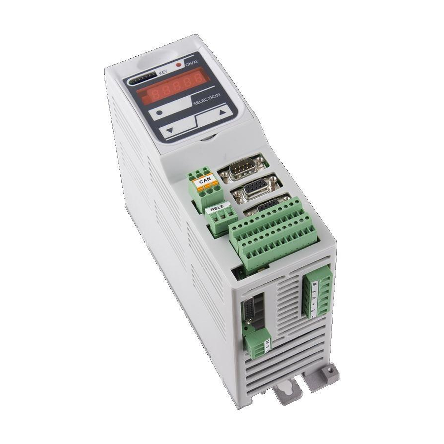
Page 101: Display
The keypad has three buttoms, “S” ( selection), “+” (increase), “-“ (reduce) and a four numbers and half display, with the decimal points and the sign “-“. OPD EXP MINIOPD EXP FIG. 1 (Physical disposition) 7.2 LAYOUT OF THE INTERNAL DIMENSIONS... -
Page 102: Parameters (Par)
(offline), reserved, modifiable only offline and after access code to the reserved parameters (P60), or reserved for the TDE MACNO, visible after having written the access code TDE MACNO parameters (P99) and modifiable only offline. The characteristics of each parameter are recognizable from the code of identification as under: FIG. -
Page 103: Application Parameters (App)
(offline), reserved, modifiable only offline and after access code to the reserved parameters (P60), or reserved for the TDE MACNO, visible after having written the access code TDE MACNO parameters (P99) and modifiable only offline. The characteristics of each parameter are recognizable from the code of identification as under: FIG. -
Page 104: Allarms (All)
The characteristics of each connection are individually recognizable of identification code as under report. FIG. 4 (Connections CON) 7.2.4 ALLARMS (ALL) Overall functions of protection of the converter, of the motor or in the application whose status to active alarm or non active alarm it may be visualized in the display. -
Page 105: Internal Values (Int)
7.2.5 INTERNAL VALUES (INT) Overall functions of protection of the converter, of the motor or in the application whose status to active alarm or non active alarm it may be visualized in the display. The actived protection, stops the converter and does flash the display, excepted if it is disabled. -
Page 106: Logic Functions Of Output (Out)
7.2.7 LOGIC FUNCTIONS OF OUTPUT (OUT) Visualization of the status, of the logical functions, of protection or sequence (for example: drive ready, converter in run) scheduled in the control, that may or may not be assigned of predicted digital output. Code of identification: FIG. -
Page 107: Main Menu
7.4 MAIN MENU Leaving from the status of rest pressing the “S” key the principal menu is gone into of circular type that contains the indication of the type of visualizable dimensions: PAR = parameters APP = application parameters CON = internal connections INT= internal dimensions ALL= allarm INP = digital input... - Page 108 “r” if they are reserved, “t” if reserved in the TDE MACNO and the letter “n” if it modification requires that the converter in not in run (offline); all the reserved parameters are of type “n”...
- Page 109 FIG. 10 (Submenu management parameters PAR) FIG. 11 (Submenu management application parameters APP) FIG. 12 (Submenu management connections CON) User’s manual...
-
Page 110: Visualization Of The Internal Dimensions (Int)
7.4.2 VISUALIZATION OF THE INTERNAL DIMENSIONS (INT) From INT You enter into the list of undermenu of the internal dimensions pressing “S”. In the list you are moving with the keys “+” or “–” till that appearing address of dimensions wanted visualize “d x x”; pressing “S” disappears the address and appear the value of the dimension. -
Page 111: Visualization Of The Input And Output (Inp And Out)
To exclude the event of an alarm You must enter into the menu to modify both the keys “+” and “–” and when the flashing point appears of the first number You can enable or disable the alarm with the keys “+”... - Page 112 FIG. 15 (Digital input INP) To note the last three digital input are about the power logical input: POWER LOGICAL INPUT STATUS (H= ON L= OFF) / PTM H= OK; L= active alarm / MAXV H= OK; L= active alarm / MAINS SUPPLY OFF H= OK;...
-
Page 113: Programming Key
7.5 PROGRAMMING KEY The programming key device allows to transfer parameters from and to the Drive inverter or between inverters. The data are stored in a EPROM type memory, so battery backup is not necessary. The switch put on the key upper front side allows to protect the stored data against possible writing procedures. -
Page 114: List Of Parameters
8 LIST OF PARAMETERS Name Description Max Default Scale P01 - Corrective factor for analog reference KP_AI1 -400.0 400.0 1 (AUX1) P02 - Corrective offset for analog reference OFFSET_AI1 -100.0 100.0 163.84 1 (AUX1) P03 - Corrective factor for analog reference KP_AI2 -400.0 400.0 2 (AUX2) - Page 115 Name Description Max Default Scale direction of rotation PRC_SPD_THR_GAIN_CHG P44 - End speed for speed PI gain change 100.0 % MOT_SPD_MAX 163.84 START_SPD_REG_KP P45 - KpV initial speed PI proportional gain 400.0 3000. START_SPD_REG_TI P46 - TiV initial speed PI lead time constant DO_SPD_REACH_THR P47 - Speed threshold for logic output o.16 100.0...
- Page 116 Name Description Max Default Scale 1200. DCBUS_REF_MAIN_LOST P98 - Voltage reference value in Support 1 220.0 TDE_PAR_KEY P99 - Access key to TDE parameters 19999 P100 - Value of access key to reserved RES_PAR_KEY_VAL 19999 parameters DRV_F_PWM P101 - PWM frequency 1000 16000 5000 ‰...
- Page 117 Name Description Max Default Scale K_FLX97 P145 - Magnetic characteristic point 8 120.0 98.1 40.96 P146 - Maximum Power dissipated on BRAKE_R_MAX_POWER 600.0 KWatt Braking resistance K_FLX100 P147 - Magnetic characteristic point 9 120.0 100.0 40.96 K_FLX102 P149 - Magnetic characteristic point 10 120.0 102.0 40.96 P150 - High precision analog speed...
- Page 118 Name Description Max Default Scale DEAD_TIME_HW P198 - Dead time hardware duration 20.0 µs MIN_PULSE P199 - Minumum command pulse duration 20.0 µs EN_AI1 P200 - Enable analog reference value A.I.1 EN_AI2 P201 - Enable analog reference value A.I.2 EN_AI3 P202 - Enable analog reference value A.I.3 AI1_SEL P203 - Meaning of analog input A.I.1...
- Page 119 Name Description Max Default Scale EN_FLDBUS_REF P247 - Enable FIELD-BUS reference values STR_MUL_AI P248 - Storing input multilpicative factor EN_STOP_POS P255 - Enabling Stop in position STOP_POS_CMD P256 - Stop in position comand selection P257 - Enabling Stop in position after EN_STOP_POS_GBOX gearbox ZERO_TOP_SEL...
- Page 120 DISPLAY_SEL C14 - Display selection C15 - Meaning of programmable analog AO1_SEL output 1 C16 - Meaning of programmable analog AO2_SEL output 2 SENSOR2_SEL C17 - Sensor2 selection C18 - Enable incremental encoder2 time EN_TIME_DEC_ENC2 decode EN_SENSOR2_TUNE C19 - Enable sensor2 auto-tuning C20 - Invert sensor2 positive cyclic EN_INV_POS2_DIR versus...
- Page 121 C74 - Enable incremental encoder time EN_TIME_DEC_ENC decode C75 - Disable Autotuning starting from DIS_DEF_START_AUTO default values EN_INV_POS_DIR C76 - Invert positive cyclic versus C77 - Enable PI speed gains EN_SPD_REG_MEM_CORR compenstation C79 - Enable negative logic for digital EN_NOT_LI inputs EN_VF_CNTL C80 - Enable V/f control...
- Page 122 Name Description Max Default Scale SENSOR_FRQ_IN D39 - Input frequency REG_CARD_TEMP D40 - Regulation card temperature °C MOT_PRB_RES D41 - Thermal probe resistance D42 - Analog Input AI1 -100 100 163.84 D43 - Analog Input AI2 -100 100 163.84 D44 - Analog Input AI3 -100 100 163.84 SPD_ISR...
- Page 124 s.p.a. tecnologie digitali elettroniche Via dell’Oreficeria, 41 - 36100 VICENZA - Italy Tel. +39 0444 343555 - Fax +39 0444 343509 www.tdemacno.it...