
Related Manuals for Siemens SIMOTION D45 Series


Summary of Contents for Siemens SIMOTION D45 Series
- Page 1 Preface Description Operator control (hardware) SIMOTION Interfaces D4x5 Technical Data Dimension drawings Manual Spare parts/accessories Standards and approvals ESD guidelines Valid for SIMOTION D425, D435, and D445 03/2007 Edition...
- Page 2 Trademarks All names identified by ® are registered trademarks of the Siemens AG. The remaining trademarks in this publication may be trademarks whose use by third parties for their own purposes could violate the rights of the owner.
-
Page 3: Preface
Preface Content of the Manual This document is part of the SIMOTION D4xx documentation package. Scope The SIMOTION D4x5 Manual is applicable to the SIMOTION D425, SIMOTION D435, and SIMOTION D445 devices. Standards The SIMOTION system was developed in accordance with ISO 9001 quality guidelines. Content of the Manual The following is a description of the purpose and use of the product Manual: •... - Page 4 A&D Technical Support: • Phone: +49 (180) 50 50 222 • Fax: +49 (180) 50 50 223 • E–mail: [email protected] • Internet: http://www.siemens.de/automation/support-request If you have any questions, suggestions, or corrections regarding the documentation, please fax or e-mail them to: •...
- Page 5 ASICs. SIMOTION D4x5 is recyclable due to its environmentally compatible materials. For environmentally friendly recycling and appropriate disposal of your old components, please contact your local Automation & Drives representative. Contact details can be found in our contacts database on the Internet at: http://www.automation.siemens.com/partner/index.asp D4x5 Manual, 03/2007 Edition...
-
Page 7: Table Of Contents
Table of contents Preface ..............................3 Description............................... 11 System overview ..........................11 System components ........................14 Approved components for SIMOTION D ..................18 Representation of SIMOTION D425 and SIMOTION D435 ............19 Representation of SIMOTION D445 ....................20 Nameplates ..........................21 Safety notes ..........................23 Operator control (hardware)........................25 Overview of operator control and display elements..............25 Operator control elements ......................26 2.2.1... - Page 8 Table of contents Rated voltage for operation of the D4x5 ..................53 Information on insulation tests, safety class, and degree of protection ........54 Dimension drawings ..........................55 Dimension drawing of D435 and D425 ..................55 Dimension drawing of D445 ......................56 Spare parts/accessories ..........................
- Page 9 Table of contents Tables Table 1-1 Product variants ...........................12 Table 1-2 Central components........................14 Table 1-3 Components on PROFIBUS DP ....................14 Table 1-4 Components on the Ethernet .......................15 Table 1-5 Components on the PROFINET ....................16 Table 1-6 Components on DRIVE-CLiQ: .....................17 Table 1-7 Optional components for the control unit: ..................17 Table 2-1...
- Page 10 Table of contents Table 4-10 Input voltage specification......................53 Table 4-11 Rated voltage for the control unit ....................53 Table 4-12 Test voltages..........................54 Table 6-1 Overview of TB30 interface......................61 Table 6-2 Interface overview of the TM31....................62 Table 6-3 TM41 interface overview ......................
-
Page 11: Description
Description System overview Overview SIMOTION D is the drive-based variant of the SIMOTION Motion Control System based on the new SINAMICS S120 family of drives. With SIMOTION D, the SIMOTION motion control functionalities and the SINAMICS drive software run on a SINAMICS closed-loop control hardware device. -
Page 12: Table 1-1 Product Variants
Description 1.1 System overview Table 1-1 Product variants Properties SIMOTION D425 SIMOTION D435 SIMOTION D445 DRIVE-CLiQ ports Axes Up to 16 Up to 32 Up to 64 Fan/battery module Optional Optional Required Minimum IPO cycle 2 ms 1 ms 0.5 ms clock Caution For a SIMOTION D445, a fan/battery module is required for operation. - Page 13 Description 1.1 System overview A SIMOTION D axis grouping generally consists of the following elements: • SIMOTION D (Control Unit) (1) This unit contains the programmable runtime system of SIMOTION and the drive software of SINAMICS S120. In principle, SIMOTION D is capable of controlling multiple axes/drives.
-
Page 14: System Components
Description 1.2 System components System components Central components SIMOTION D4x5 communicates with automation components via the following interfaces: • PROFIBUS DP • Ethernet • PROFINET (when using a CBE30) • DRIVE-CLiQ (DRIVE Component Link with IQ) The most important components of the system and their functions are shown below. Table 1-2 Central components Component... -
Page 15: Table 1-4 Components On The Ethernet
Description 1.2 System components Component Function Distributed I/O systems SIMATIC ET 200M Modular I/O system for control cabinet installation and high channel density SIMATIC ET 200S Finely modular I/O system for control cabinet installation including motor starters, safety technology, and individual grouping of the load groups SIMATIC ET 200pro Modular I/O system with IP65/66/67 degree of protection for cabinet-... -
Page 16: Table 1-5 Components On The Profinet
Description 1.2 System components PROFINET The use of a Communication Board Ethernet (CBE30) enables SIMOTION D4x5 to communicate with the following components via PROFINET: Table 1-5 Components on the PROFINET Component Function Programming device (PG/PC) ... communicates with the "SIMOTION SCOUT", STEP 7, and HMI (Human Machine Interface) engineering systems (ES). -
Page 17: Table 1-6 Components On Drive-Cliq
Description 1.2 System components The controller can communicate with the following components via DRIVE-CLiQ: Table 1-6 Components on DRIVE-CLiQ: Component Function SINAMICS S120 ... converts speed setpoints into signals for controlling the motor and supply the power required to operate the motors. Line Module (SINAMICS S120) ... -
Page 18: Approved Components For Simotion D
A detailed, regularly updated list of the I/O modules approved for use with SIMOTION, as well as notes on their use, can be found on the Internet at: http://support.automation.siemens.com/WW/view/de/11886029 In addition to the I/O modules approved for SIMOTION, all certified standard slaves can, in principle, be connected to SIMOTION if they support the following: •... -
Page 19: Representation Of Simotion D425 And Simotion D435
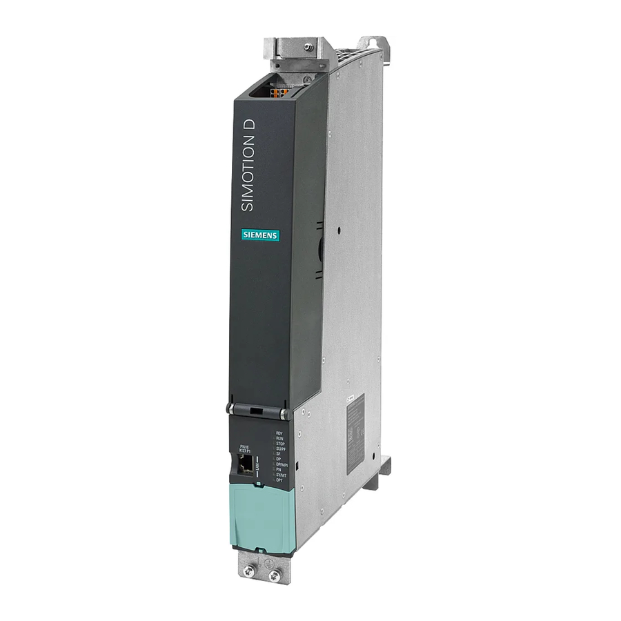
Description 1.4 Representation of SIMOTION D425 and SIMOTION D435 Representation of SIMOTION D425 and SIMOTION D435 The following figure shows the SIMOTION D425 or SIMOTION D435 with its interfaces and front panel elements (fault and status displays). Figure 1-2 Location of interfaces and front panel elements of SIMOTION D425 and SIMOTION D435 D4x5 Manual, 03/2007 Edition... -
Page 20: Representation Of Simotion D445
Description 1.5 Representation of SIMOTION D445 Representation of SIMOTION D445 The following figure shows the SIMOTION D445 with its interfaces and front panel elements (fault and status displays). Figure 1-3 Location of interfaces and front panel elements of SIMOTION D445 Caution SIMOTION D445 must be operated with a fan / battery module for heat dissipation. -
Page 21: Nameplates
Description 1.6 Nameplates Nameplates Side-mounted type plate The following figure shows you all the information included in the type plate located on the side of the unit. Figure 1-4 Type plate Note You might need to access the information provided on the side-mounted type plate after the D4x5 has been mounted. - Page 22 Description 1.6 Nameplates MAC addresses A second type plate for the MAC addresses of the two Ethernet interfaces is attached to the front of the device. You see this type plate when you open the front cover of the control unit. Figure 1-5 MAC addresses D4x5...
-
Page 23: Safety Notes
Description 1.7 Safety notes Safety notes Note the following safety information when working with the control unit and its components. Caution An option board may only be inserted and removed when the control unit and option board are disconnected from the power supply. Notice The 80 mm clearances above and below the components must be observed. -
Page 25: Operator Control (Hardware)
Operator control (hardware) Overview of operator control and display elements The following figure shows the arrangement of the operator control and display elements on the SIMOTION D4x5. Figure 2-1 Operator control and display elements The operator control and display elements are described below. D4x5 Manual, 03/2007 Edition... -
Page 26: Operator Control Elements
Operator control (hardware) 2.2 Operator control elements Operator control elements 2.2.1 Mode selector Properties of the mode selector SIMOTION D4x5 unit has a mode selector in the lower section of the front panel. The right switch labeled PLC is used for switching the operating mode of the SIMOTION D4x5. -
Page 27: Table 2-1 Mode Selector Position
Operator control (hardware) 2.2 Operator control elements Switch positions The following table contains the possible mode selector positions and the associated LED displays. The mode selector positions are explained in the order in which they are arranged on the SIMOTION D4x5. Table 2-1 Mode selector position Selector position... -
Page 28: Simotion Compact Flash Card
Operator control (hardware) 2.2 Operator control elements 2.2.2 SIMOTION Compact Flash card Slot for Compact Flash card The Compact Flash card (CF card) is inserted in the CF plug-in slot (X109 interface). Figure 2-3 Slot for Compact Flash card The CF card does not extent beyond the housing. An ergonomic recessed grip enables the CF card to be removed. -
Page 29: Reset Button
Operator control (hardware) 2.2 Operator control elements Properties of the CF card The CF card is mandatory for operation of the SIMOTION D4x5. The CF card is not supplied with the SIMOTION D4x5 and must be ordered separately. The SIMOTION Kernel and the software used to control the drives (SINAMICS firmware) are contained on the CF card. -
Page 30: Led Displays
Operator control (hardware) 2.3 LED displays LED displays Arrangement of LED displays The front panel of the SIMOTION D4x5 has eight LED displays arranged in two rows of four. Figure 2-4 LED displays on the SIMOTION D4x5 Note The 7-segment display is used exclusively for internal purposes and is not suitable for the diagnostics. -
Page 31: Table 2-3 Error And Status Displays
Operator control (hardware) 2.3 LED displays Meaning of the LED displays This table describes the LEDs and their meaning. Table 2-3 Error and status displays Meaning ... indicates the state of the integrated drive..indicates that the user program is running. STOP ... -
Page 33: Interfaces
Interfaces Interface overview This section describes the interfaces of the SIMOTION D4x5. Available interfaces Table 3-1 Overview of available external interfaces Interface Name Connector type DRIVE-CLiQ interface (0) X100 DRIVE-CLiQ plug DRIVE-CLiQ interface (1) X101 DRIVE-CLiQ plug DRIVE-CLiQ interface (2) X102 DRIVE-CLiQ plug DRIVE-CLiQ interface (3) -
Page 34: Drive-Cliq Interfaces
Interfaces 3.2 DRIVE-CLiQ interfaces DRIVE-CLiQ interfaces The DRIVE-CLiQ interfaces are used to connect the components assigned to the SIMOTION D4x5 in the drive system (e.g., Active Line Module, Motor Modules, Terminal Modules, and Sensor Modules from the SINAMICS family). DRIVE-CLiQ has the following properties: •... -
Page 35: Table 3-4 Drive-Cliq Interface (X100 - X103 Or X100 - X105)
Interfaces 3.2 DRIVE-CLiQ interfaces DRIVE-CliQ pin assignment Table 3-4 DRIVE-CLiQ interface (X100 - X103 or X100 – X105) Signal name Signal type Meaning Transmit data + Transmit data - Receive data + Reserved, do not use Reserved, do not use Receive data - Reserved, do not use Reserved, do not use... -
Page 36: Ethernet Interfaces X120 And X130
Interfaces 3.3 Ethernet interfaces X120 and X130 Ethernet interfaces X120 and X130 Interfaces for connection to Industrial Ethernet. Industrial Ethernet is a communication network with a transmission rate of 10/100 Mbit/s. SIMOTION D4x5 offers the following functions via Ethernet interfaces: •... -
Page 37: Table 3-5 X120 And X130
Interfaces 3.3 Ethernet interfaces X120 and X130 Interface features Table 3-5 X120 and X130 Features Type Connector type RJ45 socket connector Cable type Industrial Ethernet cable Maximum cable length 100 m Other The X120 and X130 interfaces are full-duplex 10/100-Mbit Ethernet ports. Both ports are wired as Ethernet terminals. -
Page 38: Digital Inputs/Digital Outputs
Interfaces 3.4 Digital inputs/digital outputs Digital inputs/digital outputs 3.4.1 Digital inputs/digital outputs X122, X132 Interface features Table 3-7 Interfaces X122 and X132 Features Type Connector type Micro Combicon Connection possibility Up to 0.25 mm Current carrying capacity 4 A, maximum Position of connectors Figure 3-3 Digital inputs and digital inputs/digital outputs (interfaces X122 and X132) - Page 39 Interfaces 3.4 Digital inputs/digital outputs Wiring and block diagram for SIMOTION D using SIMOTION D435 as an example The following figure shows the wiring diagram and the block diagram of the digital inputs and digital inputs/outputs of the SIMOTION D435. Figure 3-4 Wiring diagram and block diagram of the digital inputs/outputs D4x5...
-
Page 40: Table 3-8 Digital Inputs/Digital Outputs X122
Interfaces 3.4 Digital inputs/digital outputs Interface assignment of X122 and X132 Table 3-8 Digital inputs/digital outputs X122 Signal name Signal type Meaning Digital input 0 Digital input 1 Digital input 2 Digital input 3 Ground for DI0 - DI3 (functionally-separated relative to M) Ground DI/DO8 Digital input/digital output 8... -
Page 41: Technical Data For X122 And X132
Interfaces 3.4 Digital inputs/digital outputs 3.4.2 Technical data for X122 and X132 Digital inputs on X122/X132 Table 3-10 Technical data for digital inputs X122/X132 Parameters Values Voltage -3 V to 30 V Typical power consumption 10 mA at 24 VDC Galvanic isolation Reference potential is terminal M1 or M2 0 signal: -3 V to 5 V... -
Page 42: Use Of X122 And X123 Interfaces
Interfaces 3.4 Digital inputs/digital outputs Note An open input is interpreted as "low". The "rapid inputs" can be used in conjunction with a measuring system for position sensing. To enable the digital inputs to work, terminal M1 or M2 must be connected. This can be done as follows: •... - Page 43 Interfaces 3.4 Digital inputs/digital outputs Bidirectional digital inputs/digital outputs The control unit has 8 digital inputs/digital outputs (DI/DO). When the DI/DO are assigned as digital inputs, they can be used as follows: • Use of 6 of 8 digital inputs/digital outputs as "rapid inputs" for measuring inputs. With a signal edge at the relevant input, the current actual values of one or more encoders are measured with positioning accuracy in order to provide information for determining lengths or distances (possible with any encoders included in the project).
-
Page 44: Power Supply X124
Interfaces 3.5 Power supply X124 Power supply X124 This interface is provided exclusively for connection of the external power supply. Features of the interface Table 3-12 Interface X124 Features Type Connector type Combicon Connection possibility Up to 2.5 mm Current carrying capacity 10 A, maximum Maximum cable length 10 m... -
Page 45: Profibus Dp Interfaces X126 And X136
Interfaces 3.6 PROFIBUS DP interfaces X126 and X136 PROFIBUS DP interfaces X126 and X136 Features of the interface Table 3-14 Interfaces X126 and X136 Features Type Connector type 9-pin SUB-D socket Cable type PROFIBUS cable Maximum cable length 100 m for 12 Mbits Interface assignment for X126 Table 3-15 PROFIBUS DP interface X126... - Page 46 Interfaces 3.6 PROFIBUS DP interfaces X126 and X136 Position of connectors The following figure shows the mounting position and designation of the connectors on the control unit. Figure 3-6 Position of connectors X126, X136 Connectable devices The following devices can be connected to the PROFIBUS DP interfaces: •...
-
Page 47: Compactflash Slot
Interfaces 3.7 CompactFlash slot CompactFlash slot Features Type: 50-pin socket connector This interface should only be used to insert a special SIMOTION Compact Flash card (CF card). Consult the relevant references for detailed information about the SIMOTION CF card. See also SIMOTION Compact Flash card (Page 28) D4x5 Manual, 03/2007 Edition... -
Page 48: Measuring Sockets X131 - X134
Interfaces 3.8 Measuring sockets X131 - X134 Measuring sockets X131 - X134 Application The measuring sockets are used to output analog signals. Any interconnectable signal can be output to any measuring socket on the control unit. Caution The measuring sockets should be used exclusively for servicing purposes. The measurements may only be performed by appropriately trained specialists. -
Page 49: Technical Data
Technical Data Technical data for D435 and D425 The following technical data are relevant for the D435 and D425. Additional references For information on system clocks and address ranges of the SIMOTION D435 and SIMOTION D4x5 SIMOTION D425, refer to the Commissioning Manual. -
Page 50: Technical Data For D445
Technical Data 4.2 Technical data for D445 Ambient conditions Table 4-4 Environmental requirements Parameters Values Permissible ambient temperature Storage and transport -40° C to +70° C • • Operation 0 °C to +55 °C up to 2000 m above sea level •... -
Page 51: Table 4-6 Electrical Connection Values
Technical Data 4.2 Technical data for D445 Connection values Table 4-6 Electrical connection values Parameters Value range Supply voltage 24 VDC (permissible range: 20.4 to 28.8 V) Current consumption from 24 V Typical current consumption: 2 A (with no load at inputs/outputs, no supply from DRIVE- CLiQ I/O or PROFIBUS) Power loss 48 W... -
Page 52: Clock
Technical Data 4.3 Clock Clock Features of real-time clock The following table contains the features and functions of the control unit clock. Table 4-9 Clock features Features Meaning Type Hardware clock (integrated "realtime clock") Default setting when delivered DT#1994-01-01-00:00:00 Accuracy Max. -
Page 53: D4X5 Power Supply
Technical Data 4.4 D4x5 power supply D4x5 power supply External 24 V power supply Power is supplied to the control unit by an external 24 V power supply (e.g., SITOP). Table 4-10 Input voltage specification Input voltage Typical current Maximum current consumption consumption D425 and... -
Page 54: Information On Insulation Tests, Safety Class, And Degree Of Protection
Technical Data 4.6 Information on insulation tests, safety class, and degree of protection Information on insulation tests, safety class, and degree of protection Test voltages During the routine test, the insulation resistance is tested at the following test voltage in accordance with IEC 1131 Part 2: Table 4-12 Test voltages... -
Page 55: Dimension Drawings
Dimension drawings Dimension drawing of D435 and D425 Figure 5-1 Dimension drawing of SIMOTION D425 and SIMOTION D435 D4x5 Manual, 03/2007 Edition... -
Page 56: Dimension Drawing Of D445
Dimension drawings 5.2 Dimension drawing of D445 Dimension drawing of D445 Figure 5-2 Dimension drawing of SIMOTION D445 D4x5 Manual, 03/2007 Edition... -
Page 57: Spare Parts/Accessories
Spare parts/accessories Supplemental system components Connection options for supplemental system components Figure 6-1 Position of supplemental system components D4x5 Manual, 03/2007 Edition... -
Page 58: Fan/Battery Module
Spare parts/accessories 6.2 Fan/battery module Fan/battery module 6.2.1 Cooling the SIMOTION D4x5 Using a fan/battery module If there is insufficient free convection for heat dissipation of the control unit (with an ambient temperature greater than 55° C), an external fan/battery module can be mounted on the underside of the control unit. -
Page 59: Fan/Battery Module Assembly
Spare parts/accessories 6.2 Fan/battery module Battery A 3 V lithium battery can be inserted in the fan/battery module. The battery is preassembled with an approximately 4 cm long cable with plug. The appropriate mating connector is attached to a small printed circuit board for connection in the fan/battery module. See also List of available spare parts and accessories (Page 67) Replace battery in the fan/battery module. -
Page 60: Replace Battery In The Fan/Battery Module
Spare parts/accessories 6.2 Fan/battery module 6.2.3 Replace battery in the fan/battery module. Procedure Proceed as follows to replace the battery: 1. Gently press the fan/battery module backwards. This detaches the module from its front latching device. 2. Tilt the fan/battery module forwards at an angle and pull out the plastic guide from the recess of the control unit. -
Page 61: Terminal Board Tb30
Spare parts/accessories 6.3 Terminal board TB30 Terminal board TB30 Features of the TB30 The TB30 is a terminal expansion module that can be inserted in the D4x5. The TB30 contains the following terminals: Table 6-1 Overview of TB30 interface Interface Quantity Digital inputs Digital outputs... -
Page 62: Terminal Module Tm31
Spare parts/accessories 6.5 Terminal module TM31 Terminal module TM31 Features of the TM31 With the TM31 Terminal Module, the number of available digital inputs/digital outputs and the number of analog input/analog outputs within a drive system can be expanded. The TM31 is connected by means of DRIVE-CLiQ. -
Page 63: Terminal Module Tm41
Spare parts/accessories 6.6 Terminal module TM41 Terminal module TM41 Features of the TM41 With the TM41 Terminal Module, the number of available digital inputs/digital outputs and the number of analog inputs within a drive system can be expanded. In addition, the TTL output can be used for encoder simulation. -
Page 64: Terminal Module Tm54F
Spare parts/accessories 6.7 Terminal Module TM54F Terminal Module TM54F Features of the TM54F The TM54F offers secure digital inputs/digital outputs for control of secure motion monitoring functions. The TM54F is connected by means of DRIVE-CLiQ. Additional stations (e.g., TMxx, SMxx, MMxx) can be connected to the same DRIVE-CLiQ line, but not another TM54F. -
Page 65: Terminal Modules Tm15 And Tm17 High Feature
Spare parts/accessories 6.8 Terminal modules TM15 and TM17 High Feature Terminal modules TM15 and TM17 High Feature Features of TM15 and TM17 High Feature The TM15 and TM17 High Feature Terminal Modules are used to implement inputs of measuring inputs and outputs of output cams for SIMOTION D. In addition, these terminal modules provide drive-related digital inputs and digital outputs with short signal delay times. -
Page 66: Dmc20 Drive-Cliq Hub
Spare parts/accessories 6.9 DMC20 DRIVE-CLiQ hub DMC20 DRIVE-CLiQ hub Features The DRIVE-CLiQ hub module 20 (DMC20) is used for the star-shaped distribution of a DRIVE-CLiQ line. With the DMC20, an axis grouping can be expanded with four DRIVE- CLiQ sockets for additional subgroups. The module is especially suitable for applications which require DRIVE-CLiQ link nodes to be removed in groups, without interrupting the DRIVE-CLiQ link line and therefore the data exchange. -
Page 67: List Of Available Spare Parts And Accessories
Spare parts/accessories 6.11 List of available spare parts and accessories 6.11 List of available spare parts and accessories Table 6-5 Spare parts and accessories Parts for D4x5 Order number Accessories Spare parts CompactFlash card (CF card) 512 MB 6AU1 400-2NA00-0AA0 With drive software and SIMOTION Kernel Spacers for D425 and D435 6SL3 064-1BB00-0AA0... -
Page 69: Standards And Approvals
UL certification Recognized component mark for United States and the Canada Underwriters Laboratories (UL) in accordance with UL 508, File 16 4110. Declaration of conformity The current Declaration of Conformity is on the Internet at http://support.automation.siemens.com/WW/view/de/15257461 D4x5 Manual, 03/2007 Edition... -
Page 70: Safety Of Electronic Controllers
Standards and approvals A.2 Safety of electronic controllers Safety of electronic controllers Introduction The remarks made here relate to fundamental criteria and apply irrespective of the type of controller and the manufacturer. Reliability The reliability of devices and components is maintained at the highest possible level thanks to comprehensive and cost-effective measures implemented during the development and manufacturing processes. -
Page 71: Electromagnetic Compatibility
Standards and approvals A.3 Electromagnetic compatibility Division into safety-critical and non-safety-critical areas Nearly all systems contain parts that perform safety-related tasks (e.g. emergency stop switch, protective grating, two-hand controls). To avoid having to apply safety-related criteria to the entire controller, it is customary to divide the controller into two areas - one that is critical to safety and one that is not critical to safety. -
Page 73: Esd Guidelines
ESD guidelines ESD definition What does ESD mean? All electronic modules are equipped with highly integrated modules or components. Because of the technology used, these electronic components are very sensitive to overvoltages and thus to discharge of static electricity. The acronym ESD has become the established designation for such Electrostatic Sensitive Devices. -
Page 74: Electrostatic Charging Of Individuals
ESD guidelines B.2 Electrostatic charging of individuals Electrostatic charging of individuals Any person who is not conductively connected to the electrical potential of the environment can accumulate an electrostatic charge. This figure indicates the maximum electrostatic charges that can accumulate on an operator when he comes into contact with the indicated materials. -
Page 75: Index
Index Accessories list, 67 EMC guidelines, 69 Axis grouping, 12 ESD guideline, 73 CBE30 Fan/battery module Communication Board Ethernet, 61 Battery replacement, 60 Features, 58 Identifier, 69 Installation, 59 CompactFlash card Features, 29 Slot, 28 CompactFlash slot, 47 Guideline CX32 ESD, 73 Control Extension, 66 IEC 1131, 69... - Page 76 Index Power supply, 53 Technical data Power supply interface D425, 49 Assignment, 44 D435, 49 PROFIBUS DP interface D445, 50 Assignment, 45 Power supply, 53 Rated voltage, 53 Real-time clock, 52 Terminal Board 30, 61 Terminal Module Rated voltage, 53 TM15 and TM17 High Feature, 65 Real-time clock, 52 TM31, 62...