
Related Manuals for SolarEdge SE-MTR-3Y-400V-A


Summary of Contents for SolarEdge SE-MTR-3Y-400V-A
- Page 1 Installation Guide Energy Meter with Modbus Connection For Europe, APAC and South Africa Version 1.0...
-
Page 2: Disclaimers
SolarEdge reserves the right to make changes to the material at any time and without notice. You may refer to the SolarEdge web site (www.solaredge.com) for the most updated version. All company and brand products and service names are trademarks or registered trademarks of their respective holders. -
Page 3: Emission Compliance
Emission Compliance The images contained in this document are for illustrative purposes only and may vary depending on product models. Emission Compliance This equipment has been tested and found to comply with the limits applied by the local regulations. These limits are designed to provide reasonable protection against harmful interference in a residential installation. - Page 4 Disclaimers 3 Changes or modifications not expressly approved by the party responsible for compliance may void the user’s authority to operate the equipment. Energy Meter with Modbus Connection Installation Guide MAN-01-00643-1.0...
- Page 5 Emission Compliance Version History Version 1.0 (August 2019) - Initial release Energy Meter with Modbus Connection Installation Guide MAN-01-00643-1.0...
-
Page 6: Table Of Contents
Contents 5 Contents Disclaimers Important Notice Emission Compliance Contents HANDLING AND SAFETY INSTRUCTIONS Safety Symbols Information Chapter 1: The SolarEdge Energy Meter with Modbus Connection Package Contents Terminology Metering Applications Meter Connection Options Meter Interfaces Chapter 2: Meter Installation Installation Guidelines... - Page 7 Contents Configuring the Dual-Meter Connection Verifying the Dual-Meter Connection Troubleshooting the Dual-Meter Connection Appendix C: Monitoring Platform - Meter Data Appendix D: External Lightning Protection Appendix E: Meter Technical Specifications Support Contact Information Energy Meter with Modbus Connection Installation Guide MAN-01-00643-1.0...
-
Page 8: Handling And Safety Instructions
HANDLING AND SAFETY INSTRUCTIONS 7 HANDLING AND SAFETY INSTRUCTIONS During installation, testing and inspection, adherence to all the handling and safety instructions is mandatory. Failure to do so may result in injury or loss of life and damage to the equipment. Safety Symbols Information The following safety symbols are used in this document. - Page 9 IMPORTANT SAFETY FEATURE Denotes information about safety issues. Disposal requirements under the Waste Electrical and Electronic Equipment (WEEE) regulations: NOTE Discard this product according to local regulations or send it back to SolarEdge. Energy Meter with Modbus Connection Installation Guide MAN-01-00643-1.0...
-
Page 10: Chapter 1: The Solaredge Energy Meter With Modbus Connection
Chapter 1: The SolarEdge Energy Meter with Modbus Chapter 1: The SolarEdge Energy Meter with Modbus Connection The SolarEdge Energy Meter with Modbus Connection (also referred to as “the meter”) enables measuring the power and energy of the photovoltaic (PV) system. -
Page 11: Package Contents
Package Contents Package Contents SolarEdge Energy Meter with Modbus Connection Two DIN rail adapters Four screws Installation Guide Energy Meter with Modbus Connection Installation Guide MAN-01-00643-1.0... -
Page 12: Terminology
11 Terminology The following terms are used in this document: Export: The power injected to the grid. Import: The power purchased from the grid. Export/Import meter: A meter that is installed at the grid connection point and measures the energy/power exported/imported to/from the grid. -
Page 13: Metering Applications
Metering Applications Figure 1: Terminology Illustration Metering Applications The SolarEdge inverter or the Commercial Gateway reads data from the meter, typically using one of the scenarios illustrated in the figures below: Power production from a meter installed at the output... - Page 14 13 Figure 2: Typical installation with production meter Figure 3: Typical installation with export/import meter Figure 4: Typical installation with consumption meter Energy Meter with Modbus Connection Installation Guide MAN-01-00643-1.0...
-
Page 15: Meter Connection Options
If the inverter has a second RS485 port, use this port to connect between the inverters. If the inverter has only one RS485 port, use an RS485 Plug-In (available from SolarEdge) or ZigBee communication between the inverters. The meter is connected to one of the RS485 ports of a Commercial Gateway. -
Page 16: Meter Interfaces
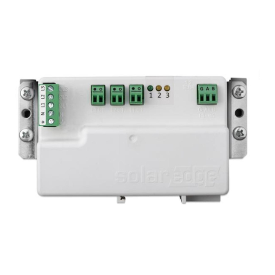
15 Figure 6: Multi-inverter connection with Commercial Gateway and meter Meter Interfaces This section describes the SolarEdge meter's interfaces. Figure 7: Meter Interfaces Voltage connections: for connection to the grid Wye: L1, L2, L3, N, Ground Energy Meter with Modbus Connection Installation Guide MAN-01-00643-1.0... - Page 17 Meter Interfaces CT connections (L1 CT, L2 CT, L3 CT): for connection to current transformers RS485: for connection to the inverter/gateway LEDs: used to monitor meter status. Modbus address DIP switches (ID 1, 2, 3): used to set the Modbus address. Termination DIP switches (TERM 1, 2): used to set RS485 termination.
- Page 18 17 Function Indication Blinking ON/OFF - normal Green Operational status operation RS485 Modbus Blinking ON/OFF - Yellow communication communication OK Single blink when the Energy Yellow meter reads an energy management change of ~1 kwH. DIP Switches Modbus Address DIP Switches The Modbus address DIP switches are used to set the Modbus address of the meter.
- Page 19 Meter Interfaces Termination DIP Switches The Termination DIP switches are used to configure RS485 wiring termination. The termination options are listed in the table below. See the figure Modbus Address and Termination DIP Switches on page 18 for switch direction guidelines. TERM TERM RS485 Termination Terminated...
-
Page 20: Chapter 2: Meter Installation
Chapter 2: Meter Installation 19 Chapter 2: Meter Installation Installation Guidelines AC wire specifications: 1.3 to 2.0 mm diameter stranded wire, 600 V, type THHN, MTW, or THWN. RS485 wiring specifications: Cable type: Min. 3-wire shielded twisted pair (a 4-wire cable may be used) Wire cross-section area: 0.2- 1 mm²... - Page 21 Installation Guidelines The meter draws 10-30 mA, therefore the rating of any switches, disconnects, fuses, and/ or circuit breakers is determined by the wire gauge, the mains voltage, and the current interrupting rating required. The switch, disconnect, or circuit breaker must be located near the meter and be easily operated .
-
Page 22: Installing And Connecting The Meter
Chapter 2: Meter Installation 21 Installing and Connecting the Meter Mount the meter either directly on a flat surface, or on a DIN rail. To mount the meter directly on a surface: 1. Using a pencil, mark the drill positions on the surface, using the four mounting holes (specified in the figure below) on the sides of the meter as a guide. - Page 23 Installing and Connecting the Meter To mount on a DIN rail using clips: The supplied kit includes two DIN-rail adapters and four screws. Figure 11: Mounting the meter on a DIN-rail 1. Attach the DIN-rail adapters to the DIN rail. 2. Connect the meter to the DIN-rail adapters, and fasten them using the supplied screws.
- Page 24 Chapter 2: Meter Installation 23 Figure 12: Alternative DIN-rail mounting To detach the meter from the DIN rail: To detach the meter from the DIN rail, insert a flat-head screwdriver into the release slot of the DIN-rail adapter shown below, and turn the screwdriver to detach the adapter from the rail.
- Page 25 Installing and Connecting the Meter Figure 13: Detaching the meter from the DIN rail To install the current transformers (CTs): NOTE If the meter is to be used for production, make sure to choose CTs that are appropriate for use with a production meter.
- Page 26 Chapter 2: Meter Installation 25 1. Turn off AC power before clamping on current transformers. 2. Install the CTs around the conductor to be measured. Split- core CTs can be opened for installation around a conductor. A nylon cable tie may be secured around the CT to prevent accidental opening.
- Page 27 Installing and Connecting the Meter To wire the meter: The meter communicates with the inverter/Commercial Gateway over an RS485 connection. Wire the meter in accordance with the three-phase connection diagrams below. Figure 14: Three Phase Grid (Wye) - Production Meter Connections Energy Meter with Modbus Connection Installation Guide MAN-01-00643-1.0...
- Page 28 Chapter 2: Meter Installation 27 NOTE Clamp the CT connected to L1 CT around the wire connected to ØL1. Clamp the CT connected to L2 CT around the wire connected to ØL2. Clamp the CT connected to L3 CT around the wire connected to ØL3. 1.
- Page 29 Installing and Connecting the Meter 4. Connect the RS485 twisted pair cable to the 3-pin terminal on the meter: a. Connect the wires to the A+ and B- terminals, and connect the shield to the G terminal. 5. Set the meter's DIP switches as follows. For general DIP switch guidelines, see "DIP Switches"...
- Page 30 2. Connect the meter's RS485 G, A+, and B- connectors to the G, A, and B connecters in the inverter. 3. If the SolarEdge device is at the end of the RS485 bus, terminate as follows: Inverter - Terminate by switching a termination DIP- switch inside the inverter to ON (top position).
- Page 31 Installing and Connecting the Meter Commecial Gateway - Terminate by switching the SW2 termination DIP-switch to ON. Figure 19: RS485 termination switch on Commercial Gateway Energy Meter with Modbus Connection Installation Guide MAN-01-00643-1.0...
-
Page 32: Chapter 3: Configuration
Chapter 3: Configuration 31 Chapter 3: Configuration SolarEdge Device Firmware Version To ensure proper communication with the meter, make sure that the inverter communication board firmware (CPU) version is 4.2.xx or later. NOTE If the inverter uses an earlier version, it will automatically upgrade the CPU to the required version upon connection of the inverter to the internet. - Page 33 SolarEdge Device Firmware Version Information CPU Version 4.2000.0000 DSP1 Version 1.0210.1066 DSP2 Version 2.0052.0410 Serial Number 7F129A09-33 › Hardware IDs › Error Log › Warning Log Energy Meter with Modbus Connection Installation Guide MAN-01-00643-1.0...
-
Page 34: Device Configuration
Chapter 3: Configuration 33 Device Configuration This section describes basic configuration of SolarEdge devices (inverter/Commercial Gateway) for use of a meter. In addition, a configuration that is specific to the application being used is required in some cases. Refer to the following documents: Export Limitation - https://www.solaredge.com/sites/default/files/feed-in_... - Page 35 Meter functionality is supported in inverters with CPU versions 4.2.xxx and above. To configure the SolarEdge meter using SetApp: 1. From the SetApp main menu, select Communication or Monitoring Communication (depending on your SetApp version), and select the port to which the meter is connected - RS485-1 or RS485-2.
- Page 36 Ext. Production: The meter is used for export limitation with 3rd party generators and for AC coupling with non-SolarEdge inverters. 6. Select Meter Protocol, and select SolarEdge. 7. Select Device ID and enter the Modbus address corresponding to the ID DIP switch settings on the meter.
- Page 37 Device Configuration Verifying the Meter Connection Verifying the Meter Connection using SetApp To verify the meter connection using SetApp: 1. From the SetApp main menu, select Status. 2. On the Status page, scroll down to the Communication status section. Check that one or more meters is connected to the RS485-1 or RS485-2 bus.
-
Page 38
Chapter 3: Configuration 37 Type and function: Displays the meter functionality (Production, Export, Import, Export+Import) Status: Displays 'OK' if the meter is communicating with the inverter.
: If an internal meter error occurs, it will be displayed here. Refer to Troubleshooting the Meter on page 39. - Page 39 Device Configuration Accessing the Meter Serial Number Accessing the Meter Serial number using SetApp To display the meter serial number using SetApp: 1. From the SetApp main menu, select Information. 2. On the Information page, select Hardware IDs. The meter serial number is found in the RGM field.
-
Page 40: Appendix A: Troubleshooting The Meter
Appendix A: Troubleshooting the Meter 39 Appendix A: Troubleshooting the Meter This appendix describes how to troubleshoot meter-related installation and performance issues. Communications Failure The following are indications of a connectivity failure between the inverter and the meter: If NC (not connected) appears for a meter in the RS485-1 or RS485-2 sub sections of the Communication page, the meter is not communicating with the inverter. - Page 41 Communications Failure If the following error message appears in the bottom left- hand corner of the Inverters section of the Status page: "Error 3x6E: Meter Comm. Error" If the status in the Meters section of the Status page is "Comm. Error" Meters Export Meter RS485-1...
- Page 42 Appendix A: Troubleshooting the Meter 41 That the meter is configured as required in the chapter "Configuration" on page 31 The RS485 wiring between the meter and the inverter/Commercial Gateway as specified in To connect the meter to the inverter or Commercial Gateway: on page There are no loose connections at the inverter connectors and at the meter, specifically the RS485 wiring.
-
Page 43: The Energy Value Is Not Advancing
The Energy Value is not Advancing The Energy Value is not Advancing Check the Energy value in the Meters section of the Status page, as shown in the figure below: Meters Export Meter RS485-1 Status Modbus ID #2 Comm. Error Power Energy 7.60 kW... - Page 44 Appendix A: Troubleshooting the Meter 43 The L1/L2/L3 AC power cables pass through the CTs in the correct direction. The arrow on the inside of the CT should point in the direction of the current source. Check for water damage or sealing problems: Inspect the entire conduit run for possible points of water penetration, and fix leaks.
-
Page 45: Appendix B: Installing Two Meters
Appendix B: Installing Two Meters Appendix B: Installing Two Meters You can connect up to two meters on the same bus. To connect two meters, install two wires into each screw terminal by twisting the wires together, inserting them into terminal, and securely tightening. - Page 46 Appendix B: Installing Two Meters 45 follows. For general DIP switch guidelines, see "DIP Switches" on page 17. a. For the meter closest to the inverter, the meter should be set for No Termination. Both switch 1 and switch 2 should be in the UP position. b.
-
Page 47: Configuring The Dual-Meter Connection
1 and an export/import meter is set to address 2. To configure the SolarEdge device using SetApp: 1. Verify that the meter at address 1 is configured as a production meter. From the SetApp main menu, select Communication è... - Page 48 Ext. Production: The meter is used for export limitation with 3rd party generators and/or for AC coupling with non-SolarEdge inverters. 5. Select Meter Protocol, and select SolarEdge. 6. Set Device ID to the address 2 (the address should correspond to the DIP switch settings).
-
Page 49: Verifying The Dual-Meter Connection
Verifying the Dual-Meter Connection 9. If used, select PT Scaling and set the potential transformer ratio. Verifying the Dual-Meter Connection Verifying the Dual-Meter Connections using SetApp To verify the connectivity of two meters using SetApp, refer to "Verifying the Meter Connection using SetApp" on page 36 Troubleshooting the Dual-Meter Connection Troubleshooting Dual-Meter Connections... -
Page 50: Appendix C: Monitoring Platform - Meter Data
Appendix C: Monitoring Platform - Meter Data If your device is connected to the SolarEdge server, you can view the meter’s readings in the monitoring platform. Verify that the meter type is set correctly in the Admin page > Logical Layout >... - Page 51 Appendix C: Monitoring Platform - Meter Data No meter installed: Displayed in Displayed in Data Monitoring Dashboard Monitoring Charts Production (inverter/site) Consumption Self-consumption Export Import Energy Meter with Modbus Connection Installation Guide MAN-01-00643-1.0...
- Page 52 Appendix C: Monitoring Platform - Meter Data 51 Export meter: Data RS485 Meter Displayed in Displayed in Monitoring Monitoring Charts Dashboard Production (inverter/site) a(calculated) Consumption (calculated) a(calculated) a(calculated) Self-consumption Export Import (1) Available from CPU version 2.10xx/3.14xx Energy Meter with Modbus Connection Installation Guide MAN-01-00643-1.0...
- Page 53 Appendix C: Monitoring Platform - Meter Data Consumption meter: Data RS485 Meter Displayed in Displayed in Monitoring Monitoring Charts Dashboard Production (inverter/site) Consumption Self- a(calculated) a(calculated) consumption a(calculated) Export a(calculated) Import Energy Meter with Modbus Connection Installation Guide MAN-01-00643-1.0...
-
Page 54: Appendix D: External Lightning Protection
SolarEdge device. This ground connection is crucial for proper suppression device operation. The ground connection should be made using a heavy gauge wire and kept as short as possible. - Page 55 Appendix D: External Lightning Protection For further information, see the Overvoltage Surge Protection Technical Note: https://www.solaredge.com/sites/default/files/lightning_ surge_protection.pdf Figure 22: Protection connection Energy Meter with Modbus Connection Installation Guide MAN-01-00643-1.0...
-
Page 56: Appendix E: Meter Technical Specifications
Appendix E: Meter Technical Specifications 55 Appendix E: Meter Technical Specifications SE-MTR-3Y-400V-A ELECTRICAL Operating Voltage Range - Nominal: 230/400 Line to Neutral / Line to Line 184-264.5 / 320-460 AC Frequency 45/65 Wye: Single Phase - L / N / PE ... - Page 57 Appendix E: Meter Technical Specifications ACCURACY (@ 25°C, PF: 1) 1% - 100% of Rated CT ±1.0 Current IEC 62053-21 Class 1, IEC Accuracy IEC 62053-23 Class 2 STANDARD COMPLIANCE IEC 61010-1, UL 61010-1, Safety CAN/CSA-C22.2 No. 61010-1-04 EN 61326: 2000, EN 61000-4-2, EN 61000-4-3, EN 61000-4-4, ...
- Page 58 102 x 102 / 158 x 168 SE-CTB-4X4.5-3000 3000 102 x 114 / 171 x 168 (1) Current transformers should be ordered separately. (2) One current transformer required per phase. For other ratings contact SolarEdge. Energy Meter with Modbus Connection Installation Guide MAN-01-00643-1.0...
-
Page 59: Support Contact Information
System configuration information, including the type and number of modules connected and the number and length of strings. The communication method to the SolarEdge server, if the site is connected. The product's software version as it appears in the status screen. - Page 60 ...