
Related Manuals for SolarEdge SE-MTR240-NN-S-S1


Summary of Contents for SolarEdge SE-MTR240-NN-S-S1
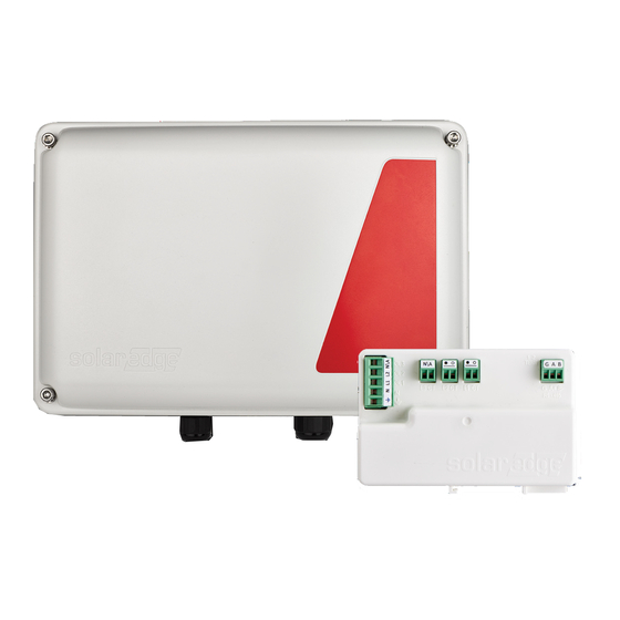
- Page 1 Installation Guide Energy Meter with Modbus Connection For North America Version 1.3...
-
Page 2: Disclaimers
The material furnished in this document is believed to be accurate and reliable. However, SolarEdge assumes no responsibility for the use of this material. SolarEdge reserves the right to make changes to the material at any time and without notice. You may refer to the SolarEdge web site (https://www.solaredge.com/us/) for the most... - Page 3 FCC Compliance Connect the equipment into an outlet on a circuit different from that to which the receiver is connected. Consult the dealer or an experienced radio/TV technician for help. Changes or modifications not expressly approved by the party responsible for compliance may void the user’s authority to operate the equipment.
-
Page 4: Version History
Version History 3 Version History Version 1.3 (August 2019) Added notation of default DIP switch settings Added label to meter showing CT connections Corrected description of LED indicators Version 1.2 (February 2019) Meter uses Wye topology configuration. Version 1.1 (January 2019) Updated for new meter hardware Addition of configuration via SetApp Version 1.0 (April 2017) - Initial release... -
Page 5: Table Of Contents
FCC Compliance Version History Contents HANDLING AND SAFETY INSTRUCTIONS Safety Symbols Information Chapter 1: Introduction Terminology The SolarEdge Energy Meter with Modbus Connection Meter Interfaces Meter Connection Meter Connection Options Chapter 2: Meter Installation Transport and Storage Package Contents Installation Equipment... -
Page 6: Handling And Safety Instructions
HANDLING AND SAFETY INSTRUCTIONS 5 HANDLING AND SAFETY INSTRUCTIONS During installation, testing and inspection, adherence to all the handling and safety instructions is mandatory. Failure to do so may result in injury or loss of life and damage to the equipment. Safety Symbols Information The following safety symbols are used in this document. -
Page 7: Chapter 1: Introduction
- three hot and one ground. The SolarEdge Energy Meter with Modbus Connection The SolarEdge Energy Meter with Modbus Connection (also referred to as “the meter”) enables measuring the power and energy of the photovoltaic (PV) system. Energy Meter with Modbus Connection MAN-01-00270-1.3... -
Page 8: Meter Interfaces
Consumption monitoring Export limitation Smart Energy on-grid applications The meter is built into an enclosure and requires two Current Transformers (CTs). The CTs are available from SolarEdge. Meter Interfaces This section describes the meter's external and internal interfaces. External Interfaces Drill guides for AC: used to feed the meter power supply as described in Installing and Connecting the Meter on page 13. - Page 9 Meter Interfaces ID DIP switches (ID 1, 2, 3): used to set the Modbus address. Termination DIP switches (TERM 1, 2): used to set RS485 termination. LEDs The meter utilizes the LEDs at the top of the unit in order to indicate current status. Figure 3: Meter LED ...
-
Page 10: Meter Connection
Figure 4: ID and Termination DIP Switches Meter Connection The SolarEdge inverter or the Commercial Gateway reads the exported/imported power from a meter installed at the grid connection point or reads the consumption from a meter installed at the load consumption point. -
Page 11: Meter Connection Options
(RGM; the inverter is referred to as a revenue grade inverter), you can connect an external meter on the same bus as the RGM (available from SolarEdge). Energy Meter with Modbus Connection MAN-01-00270-1.3... - Page 12 In a multiple inverter system, the meter is connected to the RS485 port of one of the inverters. If the inverter has only one RS485 bus, use an RS485 Plug-in (available from SolarEdge) or wireless communications between the inverters. Energy Meter with Modbus Connection MAN-01-00270-1.3...
-
Page 13: Chapter 2: Meter Installation
Chapter 2: Meter Installation Chapter 2: Meter Installation Transport and Storage Transport the Energy Meter with Modbus Connection in its original packaging, without exposing it to unnecessary shocks. If the original package is no longer available, use a similar box that can be closed fully. Store the meter in a dry place where ambient temperatures are -40°C / -40°F to +60°C / 140°F. -
Page 14: Installing And Connecting The Meter
Chapter 2: Meter Installation 13 The meter is considered “permanently connected equipment” and requires a disconnect means (circuit breaker, switch, or disconnect) and overcurrent protection (fuse or circuit breaker). The meter draws up to 100 mA, therefore the rating of any switches, disconnects, fuses, and/ or circuit breakers is determined by the wire gauge, the mains voltage, and the current interrupting rating required. - Page 15 Installing and Connecting the Meter be used. The rest of the drill guides (located at the bottom, back and sides of the enclosure, each with two sizes: ¾'' and 1'') should remain sealed. Figure 10: AC wiring drill guide 3. Install the bracket on a wall or pole, with the semi-circles facing downward, as shown below.
- Page 16 Chapter 2: Meter Installation 15 Figure 13: Meter - rear view 6. Mount the meter: Attach the meter enclosure's back brackets to the mounted bracket using the four supplied screws. Tighten the screws with a torque of 9 N*m / 6.6 lb*ft.
- Page 17 Installing and Connecting the Meter To wire the meter: Wire the meter in accordance with one of the connection diagrams below: Split phase grid, see the figure Split Phase Grid on page 16 No-neutral grid, see the figure No-Neutral Grid on page 17 If you are connecting the meter to a revenue grade inverter (inverter with built-in meter), refer to Installing Two Meters on page 35.
- Page 18 Chapter 2: Meter Installation 17 Figure 15: No-Neutral Grid NOTE Clamp the CT connected to L1 CT around the wire connected to ØL1. When clamping the CT around the conductor to be measured, make sure the arrow is pointing towards the grid. 1.
- Page 19 Installing and Connecting the Meter 2. Prepare to connect the RS485 wiring to one of the available RS485 ports of the device. Note that some inverters have one RS485 port, some have two RS485 ports. 3. Pull out the RS485 connector located on the communication board, as shown in the figure below.
- Page 20 Chapter 2: Meter Installation 19 DIP-switch inside the inverter to ON (top position). The switch is located on the communication board and is marked SW7. Figure 18: RS485 termination switch To connect the RS485 wiring to the Commercial Gateway: 1. Connect to one of one of the 3-pin connectors supplied with the Commercial Gateway to the RS485-2 connection on the Commercial Gateway.
- Page 21 Installing and Connecting the Meter Figure 20: RS485 termination switch Energy Meter with Modbus Connection MAN-01-00270-1.3...
-
Page 22: Chapter 3: Configuration
Chapter 3: Configuration Device Configuration This section describes basic configuration of SolarEdge devices (inverter/Commercial Gateway) for use of a meter. In addition, a configuration that is specific to the application being used is required in some cases. Refer to the following documents: Export Limitation - https://www.solaredge.com/sites/default/files/export_... - Page 23 Ext. Production: The meter is used for export limitation with 3rd party generators and for AC coupling with non-SolarEdge inverters. 6. Select Meter Protocol, and select SolarEdge. 7. Select Device ID and enter the Modbus address corresponding to the ID DIP switch settings on the meter.
- Page 24 Chapter 3: Configuration 23 OK/Enter (3): Selects a menu option and accepts a value change with a long press (until Applied is displayed). Use the three rightmost buttons Up, Down and OK sequentially for entering the Setup mode. Inverter Configuration – Setup Mode After inverter installation, an installer may perform basic system configuration.
- Page 25 Device Configuration To configure the SolarEdge meter using the device display: 1. Scroll to the Communication menu and select RS485-X Conf (X represents the actual RS485 port to which the electricity meter is connected: 1 or E for the inverter;...
- Page 26 Production: The meter is installed at the inverter output and reads the energy produced by the inverter. Ext. Production: The meter is used for export limitation with 3rd party generators and for AC coupling with non-SolarEdge inverters. Import: The meter is installed at the grid connection point and reads the import energy.
- Page 27 Device Configuration Verifying the Meter Connection Verifying the Meter Connection using SetApp To verify the meter connection using SetApp: 1. From the SetApp main menu, select Status. 2. On the Status page, scroll down to the Communication status section. Check that one or more meters is connected to the RS485-1 or RS485-2 bus.
- Page 28 Chapter 3: Configuration 27 information is displayed: Meters Production Meter SN: XXXXXXXX RS485-2 Status Modbus ID #1 Power Energy 7.60 kW 13.68MWh Export Meter SN: XXXXXXXX GPIO S0 meter 1000 pulses per kWh Power Energy 7.60 kW 13.68MWh 4. From the SetApp main menu, select Status. ...
- Page 29 Device Configuration D e v P r o t R S 4 8 5 - 1 < M T R > < W N > < 1 > R S 4 8 5 - 2 < - - - > < - - > < - - > Z i g B e e <...
-
Page 30: Appendix A: Troubleshooting The Meter
Appendix A: Troubleshooting the Meter 29 Appendix A: Troubleshooting the Meter This appendix describes how to troubleshoot meter-related installation and performance issues. To troubleshoot the meter using SetApp, refer to Troubleshooting the Meter using SetApp on page 29. To troubleshoot the meter using the device display, refer to Troubleshooting the Meter using the Device Display on page 32. - Page 31 Troubleshooting the Meter using SetApp If the status in the Meters section of the Status page is "Comm. Error" Meters Export Meter RS485-1 Status Modbus ID #2 Comm. Error Power Energy 7.60 kW 8.42 MWh Check the following: The meter's RS485 address DIP switch settings. Refer to "ID DIP switches" on page 8. The meter's Termination DIP switch settings.
- Page 32 Appendix A: Troubleshooting the Meter 31 The Energy Value is not Advancing Check the Energy value in the Meters section of the Status page, as shown in the figure below: Meters Export Meter RS485-1 Status Modbus ID #2 Comm. Error Power Energy 7.60 kW...
-
Page 33: Troubleshooting The Meter Using The Device Display
< - - - > < - - > < - - > Device Type or Protocol are configured incorrectly If MTR (meter) is not displayed as the device type (DEV), or SE (SolarEdge) is not displayed as the Prot (protocol), configure the meter as follows.: 1. - Page 34 The RS485 cables and connectors The AC connection of the meter If Error 185 Meter Comm. Error message is displayed, contact SolarEdge support. Total [Wh] value is not advancing If the Total [Wh] value displays a steady value although the inverter is producing power,...
- Page 35 Troubleshooting the Meter using the Device Display Check for water damage or sealing problems: Inspect the entire conduit run for possible points of water penetration, and fix leaks. Ensure that proper outdoor rated components are used. Energy Meter with Modbus Connection MAN-01-00270-1.3...
-
Page 36: Appendix B: Installing Two Meters
Appendix B: Installing Two Meters 35 Appendix B: Installing Two Meters This section describes connecting an external meter to an inverter equipped with a built-in Revenue Grade Meter (RGM), which is located in the inverter's Safety Switch. Figure 21: Connecting an external meter to an inverter with a built-in RGM Connecting Two Meters 1. - Page 37 Ext. Production: The meter is used for export limitation with 3rd party generators and for AC coupling with non-SolarEdge inverters. 5. Select Meter Protocol, and select SolarEdge. 6. Set Device ID: 2.
-
Page 38: Verifying The Meter Connection
Appendix B: Installing Two Meters 37 D e v i c e T y p e < M T R > P r o t o c o l < W N > D e v i c e < 1 > R a t i n g <... - Page 39 Verifying the Meter Connection Verifying Meter Connection using SetApp 1. From the SetApp main menu, select Status. 2. In the Communications section of the Status page, check the value of the RS485-x field, which lists: The connection protocol (for example, Modbus, SE Master, SE Slave) "x of y", where x is the number of meters configured, and y is the number of meters connected.
-
Page 40: Troubleshooting The Dual-Meter Connection
Appendix B: Installing Two Meters 39 If the SolarEdge device is connected to the SolarEdge server this value will also be displayed in the monitoring platform. Troubleshooting the Dual-Meter Connection To troubleshoot the Dual-Meter connection using SetApp, Troubleshooting Dual-Meter Connection Using SetApp on page 39. - Page 41 Troubleshooting the Dual-Meter Connection The Energy value is not advancing Check the Energy value in the Meters section of the Status page, as shown in the figure below: Meters Export Meter RS485-1 Status Modbus ID #2 Comm. Error Power Energy 7.60 kW 8.42 MWh If the Energy [in MWh] value displays a steady value even though the inverter is...
- Page 42 Appendix B: Installing Two Meters 41 Device Type or Protocol are configured incorrectly If MLT (Multi) is not displayed as the device type (DEV), or 2 is not displayed as the number of meters under Prot (protocol), configure the meters as follows: 1.
-
Page 43: Appendix C: Monitoring Platform - Meter Data
Appendix C: Monitoring Platform - Meter Data Appendix C: Monitoring Platform - Meter Data If your device is connected to the SolarEdge server, you can view the meter’s readings in the monitoring platform. Verify that the meter type is set correctly in the Admin page >... -
Page 44: Appendix D: External Lightning Protection
The ground connection should be made using a heavy gauge wire and kept as short as possible. If the cable between the SolarEdge device and the protection device must be longer than 1m/3.3 ft., a copper strap or a braided cable intended for grounding purposes must be used for the protection device to be effective. -
Page 45: Appendix E: Energy Meter With Modbus Connection Technical Specifications
0.75 or 1 / 19 or 25 in/mm Mounting Type Bracket mount Connector Type Terminal Block: 28 to 12 Current Transformers should be ordered separately: SEACT0750-200NA-20 (200A) or SEACT1250-400NA-20 (400A), 20 per box (2) For other ratings contact SolarEdge Energy Meter with Modbus Connection MAN-01-00270-1.3... -
Page 46: Support Contact Information
System configuration information, including the type and number of modules connected and the number and length of strings. The communication method to the SolarEdge server, if the site is connected. The product's software version as it appears in the ID status screen. - Page 47 ...