Cisco 6000 Series Hardware Installation Manual
Network convergence system
Hide thumbs
Also See for 6000 Series:
- Configuration manual (68 pages) ,
- Site planning manual (54 pages) ,
- Configuration manual (158 pages)
Quick Links
Cisco Network Convergence System
6000 Series Routers
Hardware Installation Guide
January 2014
Cisco Systems, Inc.
www.cisco.com
Cisco has more than 200 offices worldwide.
Addresses, phone numbers, and fax numbers
are listed on the Cisco website at
www.cisco.com/go/offices.
Text Part Number: OL-29234-02

Related Manuals for Cisco 6000 Series


Summary of Contents for Cisco 6000 Series
- Page 1 Cisco Network Convergence System 6000 Series Routers Hardware Installation Guide January 2014 Cisco Systems, Inc. www.cisco.com Cisco has more than 200 offices worldwide. Addresses, phone numbers, and fax numbers are listed on the Cisco website at www.cisco.com/go/offices. Text Part Number: OL-29234-02...
- Page 2 OR ITS SUPPLIERS HAVE BEEN ADVISED OF THE POSSIBILITY OF SUCH DAMAGES. Cisco and the Cisco logo are trademarks or registered trademarks of Cisco and/or its affiliates in the U.S. and other countries. To view a list of Cisco trademarks, go to this URL: www.cisco.com/go/trademarks.
- Page 3 3-12 Installing Power Components C H A P T E R Power System Overview Basic Chassis Power Information Bonding and Grounding Guidelines AC Power System AC Power Distribution Unit Cisco Network Convergence System 6000 Series Routers Hardware Installation Guide OL-29234-02...
- Page 4 Installing RP Cards, Line Cards, and Fabric Cards C H A P T E R About Installing Cards and Associated Components Preventing Electrostatic Discharge Guidelines for Installing and Removing a Card Cisco Network Convergence System 6000 Series Routers Hardware Installation Guide OL-29234-02...
- Page 5 10-Port 100Gbps Line Card with CXP Optics Module 5-22 60-Port 10Gbps Line Card with SFP+ Optics Module 5-25 Installing and Removing a Line Card 5-28 Installing a Line Card 5-28 Prerequisites 5-28 Cisco Network Convergence System 6000 Series Routers Hardware Installation Guide OL-29234-02...
- Page 6 Required Tools and Equipment Steps Removing an AC or DC Power Tray Prerequisites Required Tools and Equipment Steps Removing the Chassis Ground Cable Prerequisites Required Tools and Equipment Steps Cisco Network Convergence System 6000 Series Routers Hardware Installation Guide OL-29234-02...
- Page 7 Regulatory, Compliance, and Safety Specifications System Product IDs A P P E N D I X Component Product IDs Line Card Product IDs Cosmetic Product IDs Accessory Product IDs Cisco Network Convergence System 6000 Series Routers Hardware Installation Guide OL-29234-02...
- Page 8 Contents Cisco Network Convergence System 6000 Series Routers Hardware Installation Guide viii OL-29234-02...
- Page 9 Preface This document describes how to install and remove a Cisco NCS 6008 chassis and its components. The Cisco NCS 6008 chassis is a product in the Cisco Network Convergence System 6000 Series family. Chassis specifications are included in Appendix A the Cisco product IDs (PID) are listed in Appendix B.
- Page 10 SAVE THESE INSTRUCTIONS Warning Statements using this symbol are provided for additional information and to comply with regulatory and customer requirements. Cisco Network Convergence System 6000 Series Routers Hardware Installation Guide OL-29234-02...
- Page 11 Cisco technical documentation: http://www.cisco.com/en/US/docs/general/whatsnew/whatsnew.html Subscribe to the What’s New in Cisco Product Documentation as a Really Simple Syndication (RSS) feed and set content to be delivered directly to your desktop using a reader application. The RSS feeds are a free service, and Cisco currently supports RSS version 2.0.
- Page 12 Cisco Network Convergence System 6000 Series Routers Hardware Installation Guide OL-29234-02...
- Page 13 Installation Roadmap Table 1-1 lists the steps to install the Cisco NCS 6008 chassis and its components and prepare the system for operation. Use this table as a checklist to ensure that all components are properly installed in the correct order. For information about a step, see the respective section of this installation guide.
- Page 14 Power on the chassis. “Powering On the Chassis” section on page 4-29 Install cards and remaining components in the chassis. “Installing RP Cards, Line Cards, and Fabric Cards” section on page 5-1 Cisco Network Convergence System 6000 Series Routers Hardware Installation Guide OL-29234-02...
- Page 15 Fabric Cards (FCs). The Cisco NCS 6008 chassis has an integrated rack and does not require an external rack. It is bolted to the facility floor. It contains its own power and cooling systems. Power systems are available using AC or DC power.
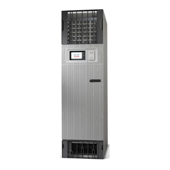
- Page 16 Front View of the Cisco NCS 6008 Chassis 1 Power trays (6) 4 Card cage with eight LC slots 2 Craft display panel 5 Air filter panel 3 Fan trays (2) 6 Air inlet plenum Cisco Network Convergence System 6000 Series Routers Hardware Installation Guide OL-29234-02...
- Page 17 Figure 2-2 Rear View of the Cisco NCS 6008 Chassis 1 Power input feeds (AC or DC) Card cage with slots for FCs and RP cards 2 Air exhaust plenum Cisco Network Convergence System 6000 Series Routers Hardware Installation Guide OL-29234-02...
- Page 18 Chassis Components Chassis Components Table 2-1 lists the main components of the Cisco NCS 6008 chassis. It identifies the components that are considered field replaceable units (FRUs), but where additional detail is useful, identifies sub-assemblies that are not field replaceable.
- Page 19 The upper three AC power trays (0-2) are contained within power shelf 0 (PS0) and the lower three AC power trays (3-5) are contained within power shelf 1 (PS1). Cisco Network Convergence System 6000 Series Routers Hardware Installation Guide OL-29234-02...
- Page 20 Six FC slots (left to right: 0, 1, 2, 3, 4, 5). The FC slots can be populated with FCs for standalone • chassis operation. See the “Component Product IDs” section on page B-1. Cisco Network Convergence System 6000 Series Routers Hardware Installation Guide OL-29234-02...
- Page 21 Chassis Overview Safety Guidelines Chassis Cable Management The Cisco NCS 6008 chassis has cable management features for both the front and rear sides of the chassis (Figure 3-3). The front and rear sides have horizontal cable management brackets above and below the card cages.
- Page 22 ESD voltage on clothing can still cause damage. Figure 2-5 shows the ESD connection socket on the front side of the chassis. Figure 2-5 ESD Connection Socket—Front Side of Chassis 1 ESD connection socket Cisco Network Convergence System 6000 Series Routers Hardware Installation Guide OL-29234-02...
- Page 23 ESD connection sockets on the rear side of the chassis. Figure 2-6 ESD Connection Sockets—Rear Side of Chassis 1 ESD connection socket (upper) 2 ESD connection socket (lower) Cisco Network Convergence System 6000 Series Routers Hardware Installation Guide OL-29234-02...
- Page 24 Chapter 2 Chassis Overview Safety Guidelines Cisco Network Convergence System 6000 Series Routers Hardware Installation Guide 2-10 OL-29234-02...
- Page 25 C H A P T E R Installing the Exterior Cosmetics This chapter provides instructions on how to install the Cisco NCS 6008 chassis exterior cosmetics. Overview of the Exterior Cosmetics, page 3-2 • Installing the Front Exterior Cosmetics, page 3-4 •...
- Page 26 Installing the Exterior Cosmetics Overview of the Exterior Cosmetics Overview of the Exterior Cosmetics The Cisco NCS 6008 chassis is shipped with exterior cosmetics for the front side and rear side of the chassis. Figure 3-1 shows the exterior cosmetics for the front side of a Cisco NCS 6008 chassis.
- Page 27 Chapter 3 Installing the Exterior Cosmetics Overview of the Exterior Cosmetics Figure 3-2 shows the exterior cosmetics for the rear side of a Cisco NCS 6008 chassis. Figure 3-2 Exterior Cosmetic s—Rear Side of Chassis 1 Rear exhaust air deflector...
- Page 28 Installing the Front Exterior Cosmetics Installing the Front Exterior Cosmetics This section describes how to install the front-side exterior cosmetics on the Cisco NCS 6008 chassis. We recommend that you install the exterior cosmetics in the order outlined in this section.
- Page 29 Exterior Cosmetics for the Front of the Chassis 1 Left vertical cable trough 3 Upper horizontal cable management bracket 2 Front door alignment bracket 4 Lower horizontal cable management bracket Cisco Network Convergence System 6000 Series Routers Hardware Installation Guide OL-29234-02...
- Page 30 (Figure 3-3). Attach the door hinge attachments, three left and three right, using two pan-head screws each Step 5 (Figure 3-5). Cisco Network Convergence System 6000 Series Routers Hardware Installation Guide OL-29234-02...