
Related Manuals for Allen-Bradley 1203-GD1


Summary of Contents for Allen-Bradley 1203-GD1
- Page 1 Allen-Bradley Getting Bulletin 1203 Remote I/O Started Communications Module Manual Catalog Numbers 1203-GD1 1203-GK1 1336-GM1...
- Page 2 Reproduction of the contents of this copyrighted publication, in whole or in part, without written permission of Allen-Bradley Company, Inc., is prohibited. Throughout this manual we use notes to make you aware of safety...
- Page 3 Summary of Changes Summary of Changes We would like to call your attention to the following changes to the 1203-5.1 manual which have occurred since the previous version published in April, 1996. All references to page, table, and figure numbers refer to the December publication. Page, table, and figure numbers in the July, 1997 publication may not match the page, table, and figure number references mentioned here due to omissions or inclusions and, likewise, text and graphics shifting somewhat from...
- Page 4 soc–ii Summary of Changes Publication 1203–5.1 – July, 1997...
-
Page 5: Table Of Contents
Table of Contents Preface Who Should Use this Manual? ......P–1 Purpose of this Manual . - Page 6 Troubleshooting Chapter 4 Chapter Objectives ........4–1 Troubleshooting Table .
-
Page 7: Preface
To efficiently use this communications module, you must be able to program and operate an Allen-Bradley programmable controller. In particular, you must be familiar with remote I/O concepts and configuration and be able to program block transfer instructions. -
Page 8: Contents Of This Manual
Component damage may result if ESD control procedures are not followed. If you are not familiar with static control procedures, reference Allen-Bradley Publication 8000-4.5.2, Guarding against Electrostatic Damage, or any other applicable ESD protection handbook. Firmware Support This manual supports communication module firmware versions 1.xx and 2.xx (the xx designator may vary). -
Page 9: Plc Product Compatibility
Preface P–3 PLC Product Compatibility This adapter is designed to be used with the following Allen-Bradley programmable controllers: PLC-2/30 with SD2 (communications module version 1.02 or later) PLC-3 SLC 500t with 1747-SN scanner PLC-5/10t, PLC-5/15t, PLC-5/25t family PLC-5/30t, PLC-5/40t, PLC-5/40Lt, PLC-5/60t,... -
Page 10: Allen-Bradley Support
P–4 Preface Allen–Bradley Support Allen–Bradley offers support services worldwide, with over 75 Sales/Support Offices, 512 authorized Distributors and 260 authorized Systems Integrators located throughout the United States alone, plus Allen–Bradley representatives in every major country in the world. Local Product Support Contact your local Allen–Bradley representative for: sales and order support product technical training... -
Page 11: Overview
The remote I/O communications module is an optional interface device designed to provide a direct, digital link between an Allen-Bradley programmable controller and any device that uses the SCANportt communication port. The current list of products that use the SCANport communications interface includes: 1305, 1336 PLUS, 1336 FORCE, 1336 IMPACT, 1397, and SMP3 and SMC Dialog Plus. - Page 12 1–2 Overview Figure 1.1 Open Style Communications Module Block Transfer Enable Logic Command / Status Enable Analog Reference / Feedback Enable Datalink A-D enable Rack Address Truncate last datalink Starting Quarter Baud Rate Rack Fault Hold Last State Adapter Fault Last Rack Status (Red) SCANport Status...
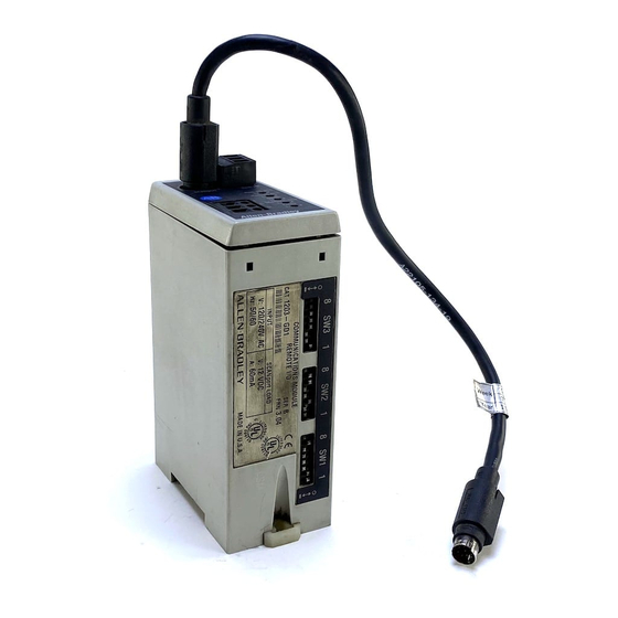
- Page 13 Overview 1–3 Figure 1.2 Enclosed Style Communications Module SCANport . . . Communication Remote I/O Cable Connector Connector Remote I/O Status (Green) Remote I/O Active (Green) Connect Adapter Health (Green) Power Supply Here SCANport Status (Green) Adapter Fault Status (Red) Front View Switch SW3 –...
- Page 14 1–4 Overview Figure 1.3 Typical Programmable Controller/SCANport Device Interconnection Open Style Adapter 1336 PLUS Remote I/O Link Communications Module Panel View Operator Terminal 1305* Micro SCANport Drive À À À À Communications Communications Module Module SMC Dialog Plus SMP 3 SCANport Other Remote I/O Devices *NOTE: Refer to Page 1–1 for compatibility...
-
Page 15: Configuration Switches
Overview 1–5 Configuration Switches The remote I/O communications module contains three DIP switches SW1, SW2, and SW3 (Figure 1.1 and Figure 1.2). Switches are set On or Off as detailed in Figure 1.4. For a detailed explanation of switch configuration, refer to Chapter 2, Installation. Figure 1.4 Configuration Switch OPEN... -
Page 16: Safety Precautions
Component damage may result if you do not follow ESD control procedures. If you are not familiar with static control procedures, refer to Allen-Bradley publication 8000-4.5.2, Guarding Against Electrostatic Damage, or any other applicable ESD Protection Handbook. -
Page 17: Installation
Chapter Installation Chapter Objectives Chapter 2 provides information to help you: set the module configuration switches mount the remote I/O module connect the remote I/O cable connect the termination resistor connect the SCANport link connect the power supply Read this chapter completely before you attempt to install or configure your remote I/O communications module. -
Page 18: Switch Sw3
2–2 Installation Switch SW3 Set switch SW3 first. The settings on this switch determine how the SCANport device uses the data contained in the programmable controller I/O image table. SW3 also establishes the minimum rack size that this communications module requires. "... - Page 19 Installation 2–3 Table 2.A SW3 Image Table Map RESERVED FOR: Minimum Start At Start At Required Group Output Image Input Image Rack Size 1/4 Rack 0, 2, 4, or 6 Half Rack lf R 0, 2, or 4 3/4 Rack 0 or 2 Full Rack ll R...
- Page 20 2–4 Installation Figure 2.2 SW3 Flowchart continued Step 4. Datalink A Transfer 1. Set SW3-4 to off Will Datalink Group A be used? 2. Move to step 5 1. Write “Datalink A” in the output and input image of the next two available words 2.
-
Page 21: Switch Sw2
Installation 2–5 Switch SW2 Switch SW2 determines Rack Size, Last State, Rack Fault, and Bit Rate Selections as shown in Figure 2.3. " The switches are labeled in the same orientation as they appear on the board. Figure 2.3 Configuration Switch SW2 Settings Enclosed Style Open Style OFF (OPEN) - Page 22 2–6 Installation Figure 2.4 PLC Switched to Program Generate a drive communications Fault drive in program set loss fault Hold last state Send a 0 command to the drive Send command on to the drive Figure 2.5 SCANport Cable Unplugged Stop responding to the PLC.
-
Page 23: Switch Sw1
Installation 2–7 Switch SW1 Switch SW1 controls starting quarter and rack address options as shown in Figure 2–7. " Note: When using a PLC-2 family processor, you need to offset the value of the rack number by one. The PLC-2 cannot have a remote I/O rack numbered zero. - Page 24 2–8 Installation Table 2.B Switch SW1 Settings SW1-8 through SW1-1 DIP Switch Definitions, Rack Address Rack No. SW1-8 SW1-7 SW1-6 SW1-5 SW1-4 SW1-3 SW1-2 SW1-1 not used not used not used not used not used not used not used not used not used not used not used...
-
Page 25: Mounting The Remote I/O Module
Installation 2–9 Mounting the Remote I/O The remote I/O communications module can be provided in three Module mounting configurations: Open Style board factory installed in a drive (not available for all drives) Open Style board as a separate kit Enclosed style for panel mount or DIN rail mount This section provides mounting information for the Enclosed style and the Open style kit. - Page 26 2–10 Installation Figure 2.9 Open Style Communications Module Mounting Location (1336 FORCE Drive) 1336 FORCE Main Control Board Open Communications Module 1336 FORCE Standard Adapter Board Mounts Here SCANport 6 L OPTION Mounting Screws & Standoffs Qty 4 " Install the board with the component side facing you. Publication 1203–5.1 ––...
- Page 27 Installation 2–11 Figure 2.10 Enclosed Style Communications Module Dimensions Side View 123 mm (4.8) Back View É É Í Í Í Í É É É É É É Í Í Í Í É É É É DIN RAIL 70 mm É...
-
Page 28: Connecting The Remote I/O Cable
2–12 Installation Connecting the Remote I/O You must connect remote I/O communications module cables as Cable shown in the example in Figure 2.11. Refer to Table 2.C for cable guidelines. Figure 2.11 Remote I/O Module Interconnections Blue É É É Shield Clear Enclosed... - Page 29 Installation 2–13 Twinaxial cable used for remote I/O (RIO) and Data Highway+ (DH+ ) communications represents a communications transmission line in which certain characteristics exist. The following are some general guidelines that must be adhered to in order to obtain the best results. Cable Type –...
-
Page 30: Connecting The Termination Resistor
2–14 Installation Connecting the You must terminate both ends of a remote I/O link to ensure proper Termination Resistor operation. This termination is required only at the ends of the physical cable. Each remote I/O network should have exactly two termination resistors installed. - Page 31 Installation 2–15 Figure 2.12 Terminating a Remote I/O Link Using the Module Mounted Resistor Blue É É Shield Clear Not Last Rack (Factory Default) Last Rack, Termination Resistor Inserted Enables 150 ohm Termination Resistor Figure 2.13 Terminating a Remote I/O Link Using an External Resistor Remote I/O Module Enclosed Remote I/O Module...
-
Page 32: Connecting The Scanport Link
(B1+ C = maximum 10 meters). 1305 Drive An Allen-Bradley SCANport link cable is used to make the connection between the communications module and the drive (Figure 2.14). Figure 2.14... -
Page 33: Smp 3
Installation 2–17 SMP 3 An Allen-Bradley SCANport cable is used to connect the communications adapter and an SMP 3. See the cable requirements on page 2–16 for details on cable length. Figure 2.15 SCANport connection on Remote I/O RESET SCANport... -
Page 34: Connecting The Power Supply
2–18 Installation Connecting the Power The Enclosed remote I/O is powered from a separate 24V dc or Supply 115V ac power supply (Figure 2.17). With the open style remote I/O board mounted in the drive, no separate power supply connections are required. -
Page 35: Configuration And
Chapter Configuration and Interfacing Chapter Objectives Chapter 3 provides information on how the remote I/O communications module and a programmable controller communicate. The following topics are covered: programmable controller data table use data transfer through the adapter Important: Block transfer messaging is covered in a separate publication. - Page 36 3–2 Configuration and Interfacing Figure 3.1 Typical Example of Data Transfer Through the Communications Module Programmable Controller I/O Image Table Rack 2 Output Image Word 0 Stop Word 1 Start Word 2 Word 3 Word 4 Clear Faults Remote I/O Word 5 Direction 1336 PLUS...
-
Page 37: Data Transfer Through The Communications Module
Configuration and Interfacing 3–3 Data Transfer Through the DIP switch SW3 determines how the data contained in the Communications Module programmable controller I/O image table is used in the drive (Figure 3.2). The first three switches (1 through 3) select the basic control features. - Page 38 3–4 Configuration and Interfacing Figure 3.2 Typical Programmable Controller Configuration Using Datalink A Programmable Remote I/O Drive Controller Communications I/O Image Table Module Output Image Blk Transfer Datalink A Logic Command Parameters Reference WORD 3 Data In A1 WORD 4 Data In A2 WORD 5 WORD 6...
- Page 39 Configuration and Interfacing 3–5 Figure 3.3 Typical Programmable Controller Configuration for 1305 and 1336 PLUS/FORCE without Block Transfer Programmable Controller Remote I/O 1336 PLUS/FORCE I/O Image Table Communications Controller Module Output Image Logic Command Parameters Reference Datalink A WORD 2 Data In A1 Data In A2 WORD 3...
- Page 40 3–6 Configuration and Interfacing Figure 3.4 Typical Programmable Controller Configuration for 1305 and 1336 PLUS/FORCE with Block Transfer Programmable Controller Remote I/O 1336 PLUS/FORCE I/O Image Table Communications Controller Module Output Image Block Transfer Logic Command Parameters Reference Datalink A Data In A1 Data WORD 3 In A2...
- Page 41 Configuration and Interfacing 3–7 Figure 3.5 Typical Programmable Controller Configuration for SMP3 Programmable Remote I/O SMP3 Controller I/O Communications Image Table Module Output Image Logic Command WORD 1 REF WORD 2 WORD 3 WORD 4 WORD 5 WORD 6 WORD 7 Input Image Logic Status Feedback...
- Page 42 3–8 Configuration and Interfacing Figure 3.6 Typical Programmable Controller Configuration for SMC Dialog Plus without Block Transfer Programmable Remote I/O SMC Dialog Plus Controller I/O Communications Image Table Module Output Image Logic Command Input Image Logic Status Feedback Current Phase A Block Transfer Off Logic Cmd/Sts On Reference/Feedback Off...
- Page 43 Configuration and Interfacing 3–9 Figure 3.7 Typical Programmable Controller Configuration for SMC Dialog Plus with Block Transfer Programmable Remote I/O SMC Dialog Plus Controller I/O Communications Image Table Module Output Image Block Transfer Logic Command Input Image Block Transfer Logic Status Feedback Current Phase A Block Transfer On...
- Page 44 3–10 Configuration and Interfacing Figure 3.8 SLC 5/02 Controller Example Example Information: PLC Type – SLC 5/02 Drive Type – 1336 PLUS Drive Rack Address – – Rack Size 1/2 Rack Minimum PLC Image Table Map Starting Module Group – OUTPUT INPUT WORD...
- Page 45 Configuration and Interfacing 3–11 SLC 5/02 Example continued When the Machine JOG Pushbutton is pressed, the PLC will send a JOG command to the drive. (Jog button is a normally open contact in this example.) Drive Machine Command Pushbutton 0 : 1.16 I : 1.8 When the Machine Clear Faults Pushbutton is pressed, the PLC sends a Clear Faults command to the drive.
- Page 46 3–12 Configuration and Interfacing Figure 3.9 PLC 5/15 Controller Example Example Information: PLC Type – PLC 5/15 Drive Type – 1336 PLUS Drive Rack Address – – Rack Size 1/2 Rack Minimum Starting Module Group – PLC Image Table Map OUTPUT INPUT WORD...
- Page 47 Configuration and Interfacing 3–13 PLC 5/15 Example continued When the Machine JOG Pushbutton is pressed, the PLC will send a JOG command to the drive. The drive will start and run at the programmed Jog Frequency if no STOP command is being sent by the PLC or other control device. (Jog button is a normally open contact in this example.) Drive Machine Command...
- Page 48 3–14 Configuration and Interfacing This Page Intentionally Left Blank. Publication 1203–5.1 –– July, 1997...
- Page 49 I/O system using the LED indicators on the front of the device (Figure 4.1). The remote I/O module is a non-serviceable device that should be returned to Allen-Bradley for replacement when a major fault exists that is attributable to the remote I/O communications module itself.
- Page 50 4–2 Troubleshooting Troubleshooting Table Table 4.A General Indications Indicator Color Probably cause Recommended action Adapter Fault Status Red (Steady) Unrecoverable fault Replace the adapter. Check configuration switch setting, check for SCANport Red (Blinking) Recoverable fault cable connection. Red (Off) Normal operation None SCANport Status Green (Steady)
- Page 51 Chapter Specifications Chapter Objectives Chapter 5 provides you with background information and specifications that you may need to install, repair, or apply your remote I/O communications module. Product Specifications Table 5.A General Indications Open Style Enclosed Style –– 115V ac Enclosed Style ––...
- Page 52 5–2 Specifications Programmable Controller This communications module is designed to be used with the Compatibility following Allen-Bradley programmable controllers: PLC-2/30 with SD2 (communications module version 1.02 or later) PLC-3 SLC500 with 1747-SN scanner PLC 5/10 , 5/15 , 5/25 family...
- Page 53 By filling out this form you can help us provide the most useful, thorough, and accurate manuals available. Please take a few minutes to tell us what you think - then mail this form or FAX it. FAX: your local Allen-Bradley Sales Office or 414/512-8579 PUBLICATION NAME ________________________________________________________________________________________________ PUBLICATION NUMBER, DATE AND PART NUMBER (IF PRESENT) _________________________________________________________ CHECK THE FUNCTION THAT MOST CLEARLY DESCRIBES YOUR JOB.
- Page 54 FOLD HERE FOLD HERE NO POSTAGE NECESSARY IF MAILED IN THE UNITED STATES BUSINESS REPLY MAIL FIRST CLASS PERMIT NO. 413 MEQUON, WI POSTAGE WILL BE PAID BY ADDRESSEE ALLEN-BRADLEY Attn: Marketing Communications P.O. Box 760 Mequon, WI 53092-9907...
- Page 55 Philippines Poland Portugal Puerto Rico Qatar Romania Russia–CIS Saudi Arabia Singapore Slovakia Slovenia South Africa, Republic Spain Sweden Switzerland Taiwan Thailand Turkey United Arab Emirates United Kingdom United States Uruguay Venezuela Yugoslavia Allen-Bradley Headquarters, 1201 South Second Street, Milwaukee, WI 53204 USA, Tel: (1) 414 382-2000 Fax: (1) 414 382-4444 Publication 1203-5.1 – July 1997 PN74001-002-01(F) Supersedes Publication 1203-5.1 –...