
Related Manuals for Sony DNW-A75


Summary of Contents for Sony DNW-A75
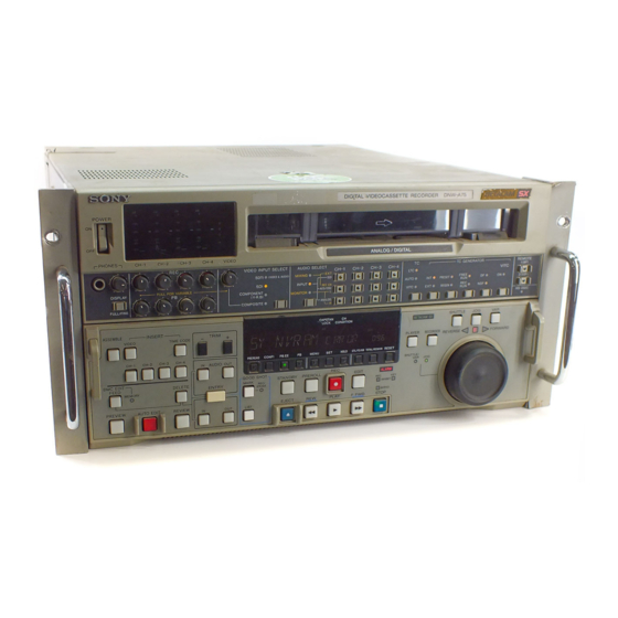
- Page 1 DIGITAL VIDEOCASSETTE RECORDER DNW-A75/A75P MAINTENANCE MANUAL Part 1 1st Edition (Revised 8) Serial No. 10001 and Higher: DNW-A75 Serial No. 40001 and Higher: DNW-A75P...
- Page 2 4. Prevention against achieving hazardous condition due to uneven mechanical loading When this product is installed in a rack, please make sure that the rack does not achieve hazardous condition due to uneven mechanical loading. DNW-A75/A75P...
- Page 3 Mettre au rebut les batteries usagées conformément aux instructions du fabricant. ADVARSEL! Lithiumbatteri-Eksplosionsfare ved fejlagtig håndtering. Udskiftning må kun ske med batteri af samme fabrikat og type. Levér det brugte batteri tilbage til leverandøren. 1 (P) DNW-A75/A75P...
-
Page 5: Table Of Contents
1-12. Reference System ..................1-25 1-13. Settings and Adjustment when External Equipment is Connected ... 1-26 1-13-1. Settings for Time Code ............1-26 1-13-2. VTR Constant Values Settings of Editor ......... 1-26 1-13-3. System Phase Alignment............1-27 1-13-4. Setup Menu Settings ..............1-27 DNW-A75/A75P... - Page 6 2-16. Battery for Memory Backup ..............2-28 2-17. Setup Menu (F-Series) ................2-29 2-17-1. Menu Operation ............... 2-29 2-17-2. F-Series Items ................2-30 3. Error Message 3-1. Overview of Error Message ................ 3-1 3-2. Details of Error Messages ................3-3 DNW-A75/A75P...
- Page 7 METER HEAD ROOM Setup Menu (M37) ......4-88 4-4-8. 50PIN DATA ASSIGN Mode (M39) ........4-88 4-5. Setup Maintenance Mode (M4) ..............4-92 4-5-1. Outline ..................4-92 4-5-2. EXTENDED MENU Display Selection Menu (M40) ..... 4-92 4-5-3. RESET ALL SETUP Executing Menu (M49) ......4-93 DNW-A75/A75P...
- Page 8 A-2. Recording Format ..................A-1 A-3. Head Configuration ..................A-5 A-4. Signal Processing ..................A-6 A-4-1. Compression System of Video Signal ........A-6 A-4-2. Outline of Signal Processing ............. A-6 Appendix B Setting Check Sheet Appendix C Circuit Description and Overall Block Diagram DNW-A75/A75P...
-
Page 9: Manual Structure
Purpose of this manual This manual is the maintenance manual part 1 of digital videocassette recorder DNW-A75/A75P. This manual is intended for use by trained system and service engineers, and provides the information that is required to install and maintenance information. -
Page 10: Related Manuals
Besides this “maintenance manual part 1”, the following manuals are available for digital videocassette recorder DNW-A75/A75P. If these manuals are required, please contact your local Sony Sales Office/Service Center..Operation Manual (Supplied with the DNW-A75/A75P.) This manual is necessary for application and operation (and installation) of the DNW. -
Page 11: Installation
1-10. Switch and Shorting Plug Settings on PC Boards 1-11. Switching Search Dial Mode 1-12. Reference System 1-13. Settings and Adjustment when External Equipment is Connected *Operation check If an error message appears on the time data display area, refer to “3. Error Message”. DNW-A75/A75P... -
Page 12: Operating Conditions
This unit does not come with a power cord. Good air circulation is essential to prevent internal heat To get a power cord, please contact your local Sony Sales build-up. Place the unit in location with sufficient air Office/Service Center. -
Page 13: Installation Space
Mass : 28.5 kg (454) 45.5 (47.1) 512.8 577(Maximum traveling distance) 415.9 31.5 15.9 12.7 123.8 263.5 457.5 18.3 47.1 Unit : mm n Remove the feet when rack mounting. Dimensions when Rack-Mounting DNW-A75/A75P... -
Page 14: Rack Mounting
The color of rack angle of RMM-111 fits to the unit. RMM-110 is the same consistance, strength and dimension as RMM-111, but the color of rack angle is different. To mount this unit in the FLEXICART, it is recommended to use the BKFC-53/2. DNW-A75/A75P... - Page 15 . Take care of the screws thread after being removed as they differs in fitting depending on the quality of materi- als of the feet. Material of the foot Screw Rubber PS4 x 20 with washer PS4 x 14 Inner rail B4 x 6 Plastic PS4 x 20 DNW-A75/A75P...
- Page 16 (PSW4 x 16). Ball retainer Tightening torque: 120 x 10 N . m {12.2 kgf . cm} B4 x 8 PSW4 x 16 Rack angle PSW4 X 16 Rack angle PSW4 x 16 DNW-A75/A75P...
- Page 17 14. Fully tighten the eight screws (B4 x 8) fixing the four rail brackets. Tightening torque: 120 x 10 N . m {12.2 kgf . cm} Rack Outer rail Rail bracket 50 to 55 mm B4 x 8 Rack angle DNW-A75/A75P...
- Page 18 20. While pressing each stopper of inner rails on both Ornamental washer sides, slowly push the unit into the rack. Be careful not to catch your finger or hand in rack mount rail. RK5 x 14 Stopper RK5 x 14 Ornamental washer Intermediate rail Stopper Inner rail DNW-A75/A75P...
-
Page 19: Matching Connectors And Cables
1-7. Matching Connectors and Cables When external cables are connected to the connector of this unit, the hardware listed below (or equiva- lents) must be used. Panel indication Matching connector (cable) Sony part No. VIDEO INPUT BNC 75Z, MALE 1-569-370-12 VIDEO OUTPUT... -
Page 20: Signal Inputs And Outputs
5 TIME CODE IN XLR 3-pin x 1 Time code 0.5 to 18 V p-p, 10 kZ, balanced 7 AUDIO INPUT (AES/EBU) BNC x 2 (1 set: CH1/2 and CH3/4) Digital audio 4 channels AES/EBU format, complies with AES-3id-1995 1-10 DNW-A75/A75P... - Page 21 Serial data transport interface (270 Mbit/s) in conformity to MPEG2 4: 2: 2 P@ML BKNW-118: Complies with SMPTE 305M (SDTI (SX)) BKNW-124: Complies with SMPTE 305M + 326M (SDTI-CP) PHONE JM-60 stereo phone jack (Upper control panel) Analog audio up to _12 dBu (8 Z load), unbalanced 1-11 DNW-A75/A75P...
- Page 22 EJECT OUT EJECT STATUS ANALOG/DIGITAL ANALOG/DIGITAL STATUS REEL HUB REEL HUB STATUS REM2 SETTING DATA RESET REMOTE2 SETTING DATA RESET STATUS ALL REC INHIBIT ALL REC INHIBIT STATUS —— —— PLAY CLOSURE SW (PLAY) STOP CLOSURE SW (STOP) 1-12 DNW-A75/A75P...
- Page 23 TXD ; Transmitted Data (Output) DTR ; Data Terminal Ready (Output) PRIORITY SG ; Signal Ground DSR ; Data Set Ready (Input) RM TX(+) RTS ; Request to Send (Output) RM RX(_) CTS ; Clear to Send (Input) 1-13 DNW-A75/A75P...
-
Page 24: Switch Settings On Connector Panel
8, 9 —— 10, 11 —— KEY RX (+) (Input) RS422 KEY TX (_) (Output) RS422 —— 15 to 17 REG +8V (Output) —— 19 to 23 —— 24 to 26 REG +8V (Output) 27, 28 —— ——- 1-14 DNW-A75/A75P... -
Page 25: Switch And Shorting Plug Settings On Pc Boards
RV700 RV800 UNITY (L) UNITY (R) –20 –20 –20 –20 –20 –20 –3 –3 –3 –3 –3 –3 COR901 COR951 >EP–GW< APR-40 Board (Side A) Refer to Section 2-13 for remov- ing/reattaching the plug-in boards. < Top View > 1-15 DNW-A75/A75P... - Page 26 Short Open Open Open Short COR201 Short Open Open RV200 Open Short Open Open Open Short COR301 Short Open Open RV300 Open Short Open Open Open Short COR401 Short Open Open RV400 Open Short Open Open Open Short 1-16 DNW-A75/A75P...
- Page 27 Short Open Open Open Short COR600 Short Open Open RV600 Open Short Open Open Open Short COR700 Short Open Open RV700 Open Short Open Open Open Short COR800 Short Open Open RV800 Open Short Open Open Open Short 1-17 DNW-A75/A75P...
- Page 28 When the variable level is selected, the level is adjusted with the PHONE level control knob. Channel Ref. No. Display Monitor output level [ ]: Factory setting [Fixed] Variable COR901 UNITY(L) Short Open VAR(L) Open Short COR951 UNITY(R) Short Open VAR(R) Open Short 1-18 DNW-A75/A75P...
-
Page 29: Board
By coupling with RV200, adjust the CH2 head amp high frequency response. This switch is used in audio head dumping adjustment. When the unit is shipped, this switch is set to the position based on the adjustment condition. 1-19 DNW-A75/A75P... - Page 30 ————— Factory use NORMAL POSITION S501 ————— Factory use S901 RF ADJUSTING Selection whether to adjust the RF or not. OFF (OPEN) OFF (OPEN) : Normal mode ON (CLOSE) : Test (adjustment) mode ————— Factory use OFF (OPEN) 1-20 DNW-A75/A75P...
-
Page 31: Tbc-23A Board
Factory use OFF (OPEN) VIDEO PHASE Selection whether to use VIDEO PHASE VR or not. OFF (OPEN) OFF (OPEN) : VIDEO PHASE VR (RV202) disabled ON (CLOSE) : VIDEO PHASE VR (RV202) enabled S500 ————— Factory use OFF (OPEN) 1-21 DNW-A75/A75P... -
Page 32: Board
1-10. Switch and Shorting Plug Settings on PC Boards 1-10-5. SS-83 Board . Never change the settings of the factory use switches/shorting plugs. . This figure is for DNW-A75. SS-83 A No. LOT No. S No. S101 S1101 S1100 S1900... - Page 33 Settable when pin No.8 is OFF. ON (CLOSE) OFF (OPEN) : Japan model ON (CLOSE) : Except Japan model 525/625 OFF (OPEN) : 525/60 model DNW-A75/TTV 4075N: OFF (OPEN) ON (CLOSE) : 625/50 model DNW-A75P/TTV 4075P: ON (CLOSE) S1900 ————— Factory use...
-
Page 34: Switching Search Dial Mode
Allow state state Search dial Back View Search dial shaft • Old type • New type Back (Upper) Back (Upper) Mode selection plate Screw Screw Front (Lower) Front (Lower) Round hole Prohibition Allow state state Search dial shaft 1-24 DNW-A75/A75P... -
Page 35: Reference System
The STOP button blinks in the following either cases. When no reference signal is input to REF. VIDEO connector. When the reference video signal (REF.VIDEO input) is not synchronized with an input video signal selected by the VIDEO INPUT SELECT button. 1-25 DNW-A75/A75P... -
Page 36: Settings And Adjustment When External Equipment Is Connected
VTR CONSTANT 1 VTR CONSTANT 2 Model name 525/625 Data No. Data No. DNW-A75 525/60 DNW-A75P 625/50 *: Set the data of No.8 of the VTR CONSTANT 1 to “0A” for the following editors. . BVE-900 ROM versions earlier than 1.08 . -
Page 37: System Phase Alignment
To prevent the picture shift during EE/PB switching in the VTR-to-VTR edit operation, this setup menu is also set to “VIDEO”. Analog Component Input/Output Format Setting “ITEM-709” (525/60 system only) Set the input (SUB-ITEM-0) and output (SUB-ITEM-1) sides to “D-1” or “B-CAM” according to the operating system, respectively. 1-27 DNW-A75/A75P... -
Page 39: Service Overview
The circuit breaker of a primary circuit is mounted on the power panel of this unit. When an overcurrent flows in the primary circuit, the breaker operates and the button protrudes. If the breaker operates, eliminate the cause for which an overcurrent flows, then push the button. DNW-A75/A75P... -
Page 40: Removing/Reattaching Cabinet
B4 x 6 BVTT3 x 6 BVTT3 x 6 B4 x 6 Right side panel Left side panel B4 x 6 Bottom plate BVTT3 x 6 B4 x 6 BVTT3 x 6 B4 x 6 B4 x 6 B4 x 6 DNW-A75/A75P... -
Page 41: Control Panels
1. Remove the upper lid. (Refer to Section 2-3-1.) 2. Remove the one screw each on the left and right sides. 3. Pull the lower control panel forward, then turn it upward. (Operation side up) Hook BVTT3 x 6 Upper control panel Hook DNW-A75/A75P... -
Page 42: Connector Panel Assembly
2. Being careful not to stretch the harnesses, remove the connector panel assembly as shown in the figure. Lugs Lower control panel BVTT3 x 6 When reattaching, install in the reverse order of removal. Connector panel assembly When reattaching, install in the reverse order of removal. DNW-A75/A75P... -
Page 43: Power Supply Panel Assembly
When reattaching, install in the reverse order of removal. Be careful not to pinch the harnesses under the plate MD To fix the ground wire, put the washer between the assembly in reattaching. terminal of ground wire and screw. DNW-A75/A75P... -
Page 44: Removing/Reattaching Cassette Compartment
(If it is put with the cassette lid down, the flexible on the CL-29 board. Keep the harness out of the way card wire/board might be damaged.) of the removal. B3 x 6 Cassette compartment Cassette compartment (with stopper) bracket assembly B3 x 6 (with stopper) Harness CN930 DNW-A75/A75P... -
Page 45: Removing/Reattaching Lower Control Panel Assembly
11. Reattach the plate MD assembly and the upper lid. Lower control panel B3 x 12 assembly Claws Notches 7. Connect the flat cable to the connector (CN145), then tie the cable with the clamp. 8. Return the lower control panel to 0d, then store. DNW-A75/A75P... -
Page 46: Circuit Function
PTC-71 Reel position sensors TR-78 S tension sensor *1: The full name of each mounted board is as follows: Model name VPR-47 DM-89 TBC-24 TBC-23A AU-260 DR-315 DNW-A75 VPR-47 DM-89 TBC-24 TBC-23A AU-260 DR-315K DNW-A75P VPR-47P DM-89P TBC-24P TBC-23AP AU-260P DR-315K *2: Either the RM-82 or the RM-181 board is used. - Page 47 SDTI (SX) output interface (optional kit BKNW-118) DPR-150 SDTI-CP output interface (optional kit BKNW-124) *3: The full name of each mounted board is as follows: Model name VR-223 VR-224 SWC-31 CP-278 CP-301 AC-169 DNW-A75 VR-223K VR-224K SWC-31K CP-278K CP-301K AC-169K DNW-A75P VR-223K VR-224K SWC-31K...
-
Page 48: Location Of Main Parts
SWC-31 ....#; SWC-35 ....#\ TBC-23A ....7 TBC-24 ....6 TC-102 ....!] TR-78 ...... @, TR-79 ...... @- VPR-47 ....3 VR-223 ....#[ VR-224 ....#] Power supply unit ... $' < Bottom View > 2-10 DNW-A75/A75P... - Page 49 2-8. Location of Main Parts < Front View > < Rear View > 2-11 DNW-A75/A75P...
- Page 50 2-8. Location of Main Parts < Top View of Mechanical Deck > < Top View of Cassette Compartment > 2-12 DNW-A75/A75P...
-
Page 51: Main Mechanical Part Locations
!/ Audio/TC head cleaner @; Cleaning roller block !- T drawer arm @' Pinch press block != TG-10 tape guide @, TG-4 tape guide ![ Pinch roller @. Threading gear block !] T reel table !\ T brake assembly 2-13 DNW-A75/A75P... -
Page 52: Function And Location Of Sensors
2-9. Function and Location of Sensors 2-9. Function and Location of Sensors < Top View of Mechanical Deck > Upper Lower < Top View of Cassette Compartment > 2-14 DNW-A75/A75P... - Page 53 These sensors are used to discriminate whether a cassette can be used in this unit. These sensors detect the movement (position) of a cassette compartment by the combination of the detection state of the two sensors and a cassette-in sensor. 2-15 DNW-A75/A75P...
-
Page 54: System Of Cassettes
4 Reel hub diameter detection tab ![ S cassette digital REC inhibit tab 5 S cassette REC inhibit plug (for metal particle tape) !] L cassette digital REC inhibit tab 6 L cassette REC inhibit plug !\ L cassette analog REC inhibit hole 2-16 DNW-A75/A75P... - Page 55 (See below) Cassette classification detection tabs : with tab (close hole), : without tab (open hole) State of Tabs Cassette Class Remark Betacam or Betacam SP ——— Betacam SX ——— Digital Betacam Unusable Except the above class Unusable 2-17 DNW-A75/A75P...
-
Page 56: Function Of Leds On Circuit Boards
Lights when SYS2 CPU does not operate normally. Blinks in bad communications between SYS2 CPU and other CPU (SYS1, SV, etc.). D2703 Green Blinks when DT MPU (IC2700) operates normally. Blinks *1: When the SS-83 board is suffix -11 or -12, “Color” is Amber. 2-18 DNW-A75/A75P... - Page 57 Scores of milliseconds 0.1 s RAM error Light on Scores of milliseconds 0.1 s 0.5 s 0.5 s Repeat System control dual port RAM error Light on 0.1 s Scores of milliseconds 0.5 s 0.5 s 0.5 s Repeat 2-19 DNW-A75/A75P...
- Page 58 (The unit automatically switches to analog playback mode and light the indicator when the cassette is ejected.) TBC-23A board LED No. Name Color Description Normal state D200 Amber Lights once a second when TBC microcomputer is under normal Blinks condition. 2-20 DNW-A75/A75P...
- Page 59 *: These LEDs operate when the received signal conforms to the EDH. (EDH: Error Detection and Handling) *1: Board No. suffix -11 only. *2: Board No. suffix -11 or -13 only. *3: Board No. suffix -14 and higher. 2-21 DNW-A75/A75P...
-
Page 60: Taking Out The Cassette In Tape Slacking
5. Pull the ME lever toward the front panel side to take up the tape inside the cassette. Wheel M gear Threading motor ME lever Cassette compartment Down motor 6. To wind up the tape, repeat steps 4 and 5. 2-22 DNW-A75/A75P... -
Page 61: Removing/Reattaching Plug-In Boards
(MB-818 board). . To reattach the board retainer, tighten the screw after inserting the protrusion of the board retainer into the square hole of chassis. Pulling out Insertion 2-23 DNW-A75/A75P... -
Page 62: Fixtures And Adjustment Equipment List
IC memory card (4 MB), MB98A81273 — Software update A-8322-417-A CN-1935 board — Connection of the IC memory card box J-6530-930-A Tension measuring tool (NTSC) [DF-093] Tape tension measurement for DNW-A75 J-6530-930-B Tension measuring tool (PAL) [DF-093] Tape tension measurement for DNW-A75P 2-24 DNW-A75/A75P... - Page 63 2-14. Fixtures and Adjustment Equipment List 2-25 DNW-A75/A75P...
-
Page 64: Equipment For Adjustment
Tektronix TSG-271 (For 625/50 system) Analog component video signal generator Tektronix TSG-300 For generating SMPTE/EBU format analog video signal (For DNW-A75) Tektronix TSG-371 For generating SMPTE/EBU format analog video signal (For DNW-A75P) Digital component video signal generator Tektronix TSG-422 (OP.1S) -
Page 65: Isr
This unit corresponds to ISR (Interactive Status Reporting) function. When this unit is connected to the personal computer which activates Sony’s ISR application software, the status of this unit or the contents of a generated error can be intensively monitored and managed on the monitor screen of a personal computer. -
Page 66: Battery For Memory Backup
Set the ID-code data. (Refer to the operation manual, the setup menu ITEM-603.) 6. Reset the calender/clock. (Refer to Section “4-3-3. Setting Mode”.) BT710 Mark BT710 Mark Mark Driver IC710 Mark IC710 Driver SS-83 board SS-83 board Board No. suffix -13 and higher Board No. suffix -11, -12 2-28 DNW-A75/A75P... -
Page 67: Setup Menu (F-Series)
. To change DATA Turn the seach dial while pressing the JOG button. . To enter the setting value Press the SET button. SET button MENU button JOG button DIGITAL VIDEOCASSETTE RECODER DNW-A75 0• 0• 0• 0• POWER -10• -10•... -
Page 68: F-Series Items
Selects the reference servo signal during pre-read operation. IN PREREAD MODE OFF: The setting of ITEM-309 is enabled. ON: The reference servo signal is set to forced EXT. (An external reference video input signal is used in this case.) (Continued) 2-30 DNW-A75/A75P... - Page 69 16 bits. OFF: The audio input data of less than 17 bits is rounded down and recorded. Set “OFF” to record a signal accurately according to the input data (i.e., record a DOLBY AC-3 encoded signal ). 2-31 DNW-A75/A75P...
-
Page 71: Error Message
PRESET PRESET PRESET PRESET PRESET PANEL CONTROL INHIBIT INHIBIT LOCK EXT INT OFF ON OFF ON INPUT REMOTE LOCAL ON OFF ON OFF MANUAL MANUAL MANUAL MANUAL MANUAL VIDEO MENU (625/50) SYSTEM PHASE CHARACTER Switch on Sub Control Panel DNW-A75/A75P... - Page 72 INTERNAL I/F 2 3-20 Abnormality in the interface between SYS2 CPU (on SS-83 board) and SERVO CPU (on SS- 83 board) or MPU (on EQ-75, DM-89, TBC-23A, or SDI-41 board) or FL (level meter module) is detected. DNW-A75/A75P...
-
Page 73: Details Of Error Messages
The messages on the time data display area differ from the messages which are superimposed on the video monitor in some items. In this section, each message indicates as following example. Ex. : ERROR-23 THREADING RING POSITION ERROR (THRED RING SENS) Message on time data display area Message superimposed on video monitor DNW-A75/A75P... - Page 74 . Take-up reel table height adjustment defect Protecting operation: Enters the protection mode. Be sure to take out the cassette manually (refer to Section 2-12). Do not turn on the power again without taking out the cassette. This may damage the tape. DNW-A75/A75P...
- Page 75 Be sure to take out the cassette manually (refer to Section 2-12). Do not turn on the power again without taking out the cassette. This may damage the tape. DNW-A75/A75P...
- Page 76 . Tape abnormality (The winding state has a problem.) Protecting operation: Enters the protection mode. Be sure to take out the cassette manually (refer to Section 2-12). Do not turn on the power again without taking out the cassette. This may damage the tape. DNW-A75/A75P...
- Page 77 . Supply or take-up reel motor drive circuit (DR-315 board) trouble . Servo adjustment defect on supply or take-up reel . Supply or take-up reel brake trouble . Supply or take-up reel brake solenoid drive circuit (MS-58 board) trouble . Harness disconnection Protecting operation: Ejects the cassette. DNW-A75/A75P...
- Page 78 . Capstan motor FG waveform shaper circuit (MS-58 board) trouble . Capstan FG duty adjustment defect Protecting operations: Ejects the cassette for No. 1 in detecting conditions. Stops the tape transport and enters the rest state for No. 2 and No. 3 in detecting conditions. DNW-A75/A75P...
- Page 79 . Threading motor drive circuit (DR-315 board) trouble . Threading mechanism trouble Protecting operations: Ejects the cassette during cassette insertion or ejection. Enters the protection mode during tape threading/unthreading. Stops the tape transport and enters the rest state in cases except the above. DNW-A75/A75P...
- Page 80 Prohibits the cleaning roller operation. Stops the tape transport and enters the rest state in the unthread end state when the tape is threaded in states other than PLAY and REC mode. Prohibits the tape threading. Prohibits the cassette insertion. 3-10 DNW-A75/A75P...
- Page 81 During tape transport in forward direction, the FF mode can be entered only while the total tape quantity is observed. Stops the tape transport and enters the rest state during tape transport except the above. 3-11 DNW-A75/A75P...
- Page 82 During the tape transport in reverse direction, the REW mode can be entered only while the total tape quantity is observed. Stops the tape transport and enters the rest state during tape transport except the above. 3-12 DNW-A75/A75P...
- Page 83 Relations of fan motors and operation state, ports, power switch circuit are as follows. Operation state FG input port For rear Always rotating IC500/SS-83 board For mechanical deck Always rotating IC115/SS-83 board For power supply unit Always rotating IC115/SS-83 board 3-13 DNW-A75/A75P...
- Page 84 . Reel position sensor (PTC-71 board) trouble (S position sensor or L position sensor) . Reel position input port (IC1 on MS-58 board) trouble Protecting operation: Stops the movement of the reel table and ejects the cassette during cassette loading. 3-14 DNW-A75/A75P...
- Page 85 . Thread end or unthread end input port (IC1 on MS-58 board) trouble Protecting operations: Ejects the cassette during cassette insertion or ejection. Enters the protection mode during tape threading/unthreading. Stops the tape transport and enters the rest state in cases except the above. 3-15 DNW-A75/A75P...
- Page 86 83 board) trouble . RM-179 board’s NV-RAM (IC1) or IC2 trouble RM-190 board’s NV-RAM (IC11) trouble Protecting operations: When the sub error message is “SY2”, enters the protection mode. When it is except above, displays only this error. 3-16 DNW-A75/A75P...
- Page 87 NV-RAM on RM-179/190 board is abnormal and the setting data is reset. Possible cause: IC1 or IC2 on RM-179 board trouble IC11 on RM-190 board trouble Protecting operation: Resets the 50-pin parallel remote (REMOTE-2) setting data to the factory setting. 3-17 DNW-A75/A75P...
- Page 88 When the error occurs in ID data, resets the data to 00 00 00 00. When the error occurs at the calendar/clock function, resets the date and time data to ’96 11 01 00 00 00 (= Year, Month, Day, Hour, Minute, Second). 3-18 DNW-A75/A75P...
- Page 89 DM: When the error occurs in an NV-RAM (IC908 on DM-89 board) during the data write or read. TBC: When the error occurs in an NV-RAM (IC200 on TBC-23A board) during the data write or read. Possible causes: Trouble of an NV-RAM indicated by sub error message Protecting operation: None 3-19 DNW-A75/A75P...
- Page 90 . Cable (between FP-117 board and level meter module) connection defect or disconnection . Level meter module trouble Protecting operations: When the sub error message is “SV”, enters the protection mode. When it is except above, displays only this error. 3-20 DNW-A75/A75P...
-
Page 91: Maintenance Mode
M36:HOUR METER RESET M37:METER HEAD ROOM M39:50PIN DATA ASSIGN M3F:MEMORY CARD UTILITY M4 : SETUP MAINTENANCE ... (Section 4-5) SETUP MAITENANCE MODE This mode is used for the setup menu. M40 : EXTENDED MENU M49 : RESET ALL SETUP DNW-A75/A75P... - Page 92 In a time data display area, the display is replaced and the specified item blinks. (“JOG DIAL” is displayed on the video monitor.) The data value or setting can be changed when the search dial is turned while pressing the 7 JOG button. DNW-A75/A75P...
- Page 93 Location of Switches on SS-83 Board (Suffix -11, -12) Remove the upper lid referring to Section 2-3-1 when operating the switches on the SS-83 board. Change the setting of DIP switch S1100 with the power switch set to OFF. DNW-A75/A75P...
- Page 94 1. Press the 2 MENU button several times to display the mode screen on the video monitor. The selected mode No. and title are displayed in a time counter. 2. Press the 2 MENU button again to terminate the maintenance mode. DNW-A75/A75P...
- Page 95 C0 -SERV C1 -RF C Display the mode (menu) which you wish to open O/DT CHE HECK and press the SET button. Turn search dial The mode (menu) is then opened. Example in Time Data Display Area DNW-A75/A75P...
-
Page 96: Tape Maintenance Mode (M0)
C0 : SERVO/DT CHECK C1 : CHECK C2 : AUDIO/VIDEO CHECK C3 : BETACAM PB CHECK A0 : SERVO/DT ADJUST A1 : ADJUST A2 : AUDIO/VIDEO ADJUST A3 : BETACAM PB ADJUST A4 : MECHANISM ADJUST TAPE Maintenance Mode DNW-A75/A75P... - Page 97 This mode is used to check the analog DT system. For more details, refer to Section 4-2-3 (on page 4-29). SERVO/DT CHECK ANALOG DT CHECK [SET] C00-03:SERVO CHECK C60:SG LOOP CHECK C04:ANALOG DT CHECK [MENU] Title Page Description C060 : SG LOOP CHECK 4-29 Checks the feedback loop of the strain gauge for analog Betacam playback. DNW-A75/A75P...
- Page 98 Displays the result of self diagnostic in DPR-118 board. C25 : DPR-119 DIAG INFO 4-41 Displays the result of self diagnostic in DPR-119 board. (Used for BKNW-118.) C26 : DPR-150 DIAG INFO 4-42 Displays the result of self diagnostic in DPR-150 board. (Used for BKNW-124.) DNW-A75/A75P...
- Page 99 For more details, refer to Section 4-2-6 (on page 4-44). BETACAM PB CHECK MODE C30:CHANNEL CONDITION Title Page Description C30 : CHANNEL CONDITION 4-44 Checks the RF level condition for each video channel (Y and C) to be played back. DNW-A75/A75P...
- Page 100 Adjusts the offset level of an analog Betacam PB head. A031 : DRIVE GAIN 4-55 Adjusts the drive gain of an analog DT system. A032 : DATA SAVE 4-57 Saves the adjustment data in an analog DT system. 4-10 DNW-A75/A75P...
- Page 101 Automatically adjusts the gain when a PB RF signal is converted from analog to digital. A17 : A11-A16 ALL ADJUST 4-63 Continuously executes the above automatic adjustment menus A11 to A16. A1F : NV-RAM CONTROL 4-65 Saves the adjustment data in an RF system. 4-11 DNW-A75/A75P...
- Page 102 A25 : DEC VR 4-73 Adjusts the composite video input system. A26 : DEC VR (LOOP) 4-73 Adjusts the composite video input (in the multi-loop state). A2F : NV-RAM CONTROL 4-74 Saves the adjustment data in audio and video systems. 4-12 DNW-A75/A75P...
- Page 103 This submode is used to adjust the mechanism part. For more details, refer to Section 4-2-12 (on page 4-78). MECHANISM ADJUST A40:PATH MODE SEL Title Page Description A40 : PATH MODE SEL 4-78 Sets the tape PB mode. (Used for tape transport adjustment.) 4-13 DNW-A75/A75P...
-
Page 104: Servo Check Mode (C00-03)
C04 : ANALOG DT CHECK (Describes in Section 4-2-3.) Menu Tree of Servo System Check Mode When the unit has a cassette tape, the cassette tape is automatically ejected on shifting to any lower-level menu from the C00-03 : SERVO CHECK menu. 4-14 DNW-A75/A75P... - Page 105 4 Spare sensor 2 5 Spare sensor 1 6 Digital/analog tape sensor 9 L cassette (SP) REC inhibit switch Sensor 8 L cassette (SX) REC inhibit switch Sensor 7 S cassette REC inhibit switch Sensor Locations of Sensors (Switches) 4-15 DNW-A75/A75P...
- Page 106 Push the cassette window up manually. Push the switch in the direction of thick arrow. Locations of Switches in Compartment Block < Top view > Rear Cassette compartment PC-70 board Front Cassette-in sensor (L) Cassette size sensor Cassette-in sensor (R) Locations of Sensors 4-16 DNW-A75/A75P...
- Page 107 . Check the oscillator and detection circuit on the MS-58 board for sensors. . Check the corresponding sensor input port (IC115 on the SS-83 board). Tape top sensor Tape end sensor Locations of Tape Top and Tape End Sensors 4-17 DNW-A75/A75P...
- Page 108 DEW SENSOR : WET! . Check each sensor itself. . Check the detection circuit on the MS-58 board. . Check the sensor input port of MPU (IC1 on the MS-58 board). Dew condensation sensor Location of Dew Condensation Sensor 4-18 DNW-A75/A75P...
- Page 109 . Check an S or T brake solenoid using a submenu C021 or C022. FG sensor for S reel table FG sensor for T reel table S reel table T reel table (S cassette position) Locations of Reel Table FG Sensors 4-19 DNW-A75/A75P...
- Page 110 . Check the threading end sensor or unthreading end sensor on the TR-79 board. . Check the sensor input port of MPU (IC1 on the MS-58 board). Unthreading end sensor Threading motor Threading end sensor Threading ring (Unthreading end state) Locations of Threading End and Unthreading End Sensors 4-20 DNW-A75/A75P...
- Page 111 . Check the cassette-down sensor (s) on the CL-29 board. DOWN . Check the sensor input port of MPU (IC1 on the MS-58 board). Rear Upper Cassette-down sensor (1) Lower Cassette-down sensor (2) Cassette compartment motor Front Top View of Cassette Compartment 4-21 DNW-A75/A75P...
- Page 112 . Check the capstan FG shaping circuit on the MS-58 board. SERVO CHECK MOTOR CHECK . Check each circuit that processes the capstan FG on the SS-83 board. C014:CAPSTAN MOTOR . Check the capstan motor. FORWARD..OK Capstan shaft (Unthreading end state) Location of Capstan Shaft 4-22 DNW-A75/A75P...
- Page 113 . Check the drum FG/PG shaping circuit on the DR-315 board. . Check each circuit that processes the drum FG/PG on the SS-83 board. After about 3 sec. SERVO CHECK MOTOR CHECK C015:DRUM MOTOR SPEED : PHASE : LOCK EXIST 4-23 DNW-A75/A75P...
- Page 114 . Check the sensor input port of MPU (IC1 on the MS-58 board). T reel table S reel table (S cassette position state) L position sensor S position sensor Reel shift motor Locations of S and L Position Sensors and Reel Shift Motor 4-24 DNW-A75/A75P...
- Page 115 . Check the mechanical abnormality. . Check the pinch roller solenoid driver circuit on the DR-315 board. . Check the pinch roller solenoid itself. Pinch roller solenoid Pinch lever Capstan (Unthreading end state) Locations of Pinch Roller Solenoid and Pinch Lever 4-25 DNW-A75/A75P...
- Page 116 . Check the reel brake solenoid driver circuit on the DR-315 board. . Check the reel brake solenoid itself. T reel table S reel table (S cassette position state) Cores S reel brake solenoid T reel brake solenoid Locations of Reel Brake Solenoids 4-26 DNW-A75/A75P...
- Page 117 . Check the mechanical abnormality. . Check the cleaning roller solenoid driver circuit on the DR-315 board. . Check the cleaning roller solenoid itself. Cleaning roller solenoid Cleaning roller (Unthreading end state) Locations of Cleaning Roller and Cleaning Roller Solenoid 4-27 DNW-A75/A75P...
- Page 118 S reel torque adjustment (A006). In case of NG during (C037) T REEL MOTOR TORQUE Perform the T reel motor check (C011). If no abnormality is found in the motor or its drive circuit, perform the T reel torque adjustment (A007). 4-28 DNW-A75/A75P...
-
Page 119: Analog Dt Check Mode (C04)
“When failing the automatic check” on the right. (5) To exit the menu, press the MENU button once. # CHECK INCOMPLETE # . The cassette tape will automatically be ejected in EJECT TAPE exiting the menu. Ex.: When failing the automatic check 4-29 DNW-A75/A75P... -
Page 120: Rf Check Mode (C1)
GRN. If there is at least . If abnormality exists in the servo system, this menu does one channel whose condition is YEL or RED, the not function properly. worst condition is displayed on the right of “ALL”. 4-30 DNW-A75/A75P... - Page 121 . Keep the unit until automatic check is completed. Check cannot be properly performed in other mode than PLAY mode. If the unit enters into other mode than PLAY mode, the check freezes or the condition becomes “RED”. 4-31 DNW-A75/A75P...
- Page 122 (Refer to the maintenance manual part 2, volume-1.) . Harness (between EQ-75 board and drum assembly) connection defect . RF system adjustment defect 8 Readjust the RF system. (A1 : RF ADJUST) (omitted) . EQ-75 board defect . Drum assembly defect (continue) 4-32 DNW-A75/A75P...
- Page 123 When no abnormality is found, the recheck is completed. (8) Clean the drum (video heads) with a cleaning cloth according to Sections 5-2-2 and 5-2-3 (9) Recheck in the menu C11 using the alignment tape. When no abnormality is found, the recheck is completed. 4-33 DNW-A75/A75P...
- Page 124 “ALL” when the conditions for all channels are GRN. If there is at least one channel whose condition is YEL or RED, the worst condition is displayed on the right of “ALL”. 4-34 DNW-A75/A75P...
- Page 125 . Keep the unit until automatic check is completed. Check cannot be properly performed in other mode than REC mode. If the unit enters into other mode than REC mode, the check freezes or the condition becomes “RED”. 4-35 DNW-A75/A75P...
- Page 126 (Refer to the maintenance manual part 2, volume-1.) RSLT RSLT . Harness (between EQ-75 board and drum assembly) connection defect . RF system adjustment defect 8 Readjust the RF system. (A1 : RF ADJUST) . EQ-75 board defect (omitted) . Drum assembly defect (continue) 4-36 DNW-A75/A75P...
-
Page 127: Audio/Video Check Mode (C2)
8 Readjust the tape transport system or reinstall the part. (Refer to the maintenance manual part 2, volume-1.) activated. . EQ-75 board defect . Be sure to perform under the no cassette tape state when selecting the system E-E to enable. . Drum assembly defect 4-37 DNW-A75/A75P... - Page 128 . The output signal of a test signal generator can also be recorded on the tape. In this case, press the SET button to display the white square in the upper-right position of the superimposed display, before recording. 4-38 DNW-A75/A75P...
- Page 129 (1) Select the C24 : DPR-118 DIAG INFO menu. (2) To scroll the screen, turn the JOG dial. Downward: Turn it in REVERSE (3) direction. Upward: Turn it in FORWARD (2) direction. (3) Press the MENU button to terminate the menu after checking the self-diagnosis result. 4-39 DNW-A75/A75P...
- Page 130 144, 146 to 149 5. ECC ENC INIT. NG IC402 Pins 45, 49 to 59 6. OUTER INIT. NG IC600 Pins 9 to 16, 20 to 23 7. SX DEC INIT. NG IC800 Pins 44 to 7, 53 to 59, 62 4-40 DNW-A75/A75P...
- Page 131 (1) Select the C25 : DPR-119 DIAG INFO menu. (2) To scroll the screen, turn the JOG dial. Downward: Turn it in REVERSE (3) direction. Upward: Turn it in FORWARD (2) direction. (3) Press the MENU button to terminate the menu after checking the self-diagnosis result. 4-41 DNW-A75/A75P...
- Page 132 IC1000 (XC4036XLA) Initial-verify only INPUT PARITY ERR IC1100 and IC1101 on DPR-118 board *: When the DPR-150 board’s board number suffix is -11, this IC CXD9139GF is IC300 on the piggybacked DIF-109 board on to the DPR- 150 board. 4-42 DNW-A75/A75P...
- Page 133 PARITY ERR MEP IC300 (Internal connection of IC300) PARITY ERR STREAM IC300 (Pins 88 to 95, 98, 112) CLOCK ERR 13.5M IC300 CLOCK ERR 27M (Pins 99, 120 to 124, 127 to 132) CLOCK ERR 54M CLOCK ERR 81M 4-43 DNW-A75/A75P...
-
Page 134: Betacam Pb Check Mode (C3)
SDRAM ERR ALL IC500, [IC501] PARITY ERR MEP IC500 (Internal connection of IC500) DNW-A75’s Betacam/Betacam SP PB function is for the PARITY ERR STREAM IC500 (Pins 88 to 95, 98, 112) NTSC (525/60) system. But the PAL (625/50) system can CLOCK ERR 13.5M... - Page 135 . Worm PB head 8 After checking the hours meter (H02 : DRUM RUNNING HOURS), replace the upper drum assembly as required. (Refer to the maintenance manual part 2, volume-1.) . Drum assembly defect . EQ-75 board defect 4-45 DNW-A75/A75P...
-
Page 136: Servo Adjust Mode (A00-01)
The menu title of A010 may be displayed as “CAPSTAN SPEED”. A02 : ANALOG DT ADJUST (Describes in Section 4-2-8.) When the unit has a cassette tape, the cassette tape is automatically ejected on shifting to any lower-level menu from the A00-01 : SERVO ADJUST menu. 4-46 DNW-A75/A75P... - Page 137 SAVE SERVO ADJUST Check [MENU] DATA in A012 : NV-RAM CONTROL menu. Data save A012:NV-RAM CONTROL SERVO ADJUST A001-008:AUTO ADJUST A006:S REEL TORQUE # ADJUST INCOMPLETE # # S REEL TROUBLE Ex.: When failing the automatic adjustment 4-47 DNW-A75/A75P...
- Page 138 (3) To exit the menu, press the MENU button once. (4) To save the adjustment data into the NV-RAM of a servo system, execute the SAVE SERVO ADJUST DATA in A012 : NV-RAM CONTROL menu. Ex.: When failing the automatic adjustment 4-48 DNW-A75/A75P...
- Page 139 DATA in A012 : NV-RAM CONTROL menu. 1.20 and higher. When it is earlier than 1.20, the message “SET SR2-1 ALIGNMENT TAPE AND PUSH PLAY KEY” is displayed. However, it is not necessary to press the PLAY button. 4-49 DNW-A75/A75P...
- Page 140 (5) To exit the menu, press the MENU button once. # ADJUST INCOMPLETE # (6) To save the adjustment data into the NV-RAM of a servo system, execute the SAVE SERVO ADJUST DATA in A012 : NV-RAM CONTROL menu. PG DATA:C000 Ex.: When failing the automatic adjustment 4-50 DNW-A75/A75P...
- Page 141 When “# S REEL TROUBLE #” is displayed in these menus: 8 Execute the S reel FG duty adjustment (A001 : S REEL FG DUTY) again. 8 Check the S reel motor driver circuit on the DR-315 board. 4-51 DNW-A75/A75P...
- Page 142 “DATA SAVED” will be displayed on the superim- NO OPERATION posed display and “A0121 10” will be displayed in SAVE SERVO ADJUST DATA the time data display area. (4) To exit the menu, press the MENU button once. DATA SAVED Check [MENU] 4-52 DNW-A75/A75P...
-
Page 143: Analog Dt Adjust Mode (A02)
(8) To save the adjustment data into the NV-RAM of a DT system, execute the SAVE ANALOG DT DATA in A032 : DATA SAVE menu. The alignment tape will automatically be ejected in returning to the A0 : SERVO/DT ADJUST mode picture. 4-53 DNW-A75/A75P... - Page 144 Start auto adjust Ach manual adjust Bch manual adjust ADJUSTING..Ach:00 Bch:00 ANALOG DT ADJUST A030:HEAD OFFSET LEVEL MODE : PLAY Start auto adjust Ach manual adjust Bch manual adjust ADJUST COMPLETE Ach:01 Bch:FF Check [MENU] Data save A032:DATA SAVE 4-54 DNW-A75/A75P...
- Page 145 (9) To save the adjustment data into the NV-RAM of a DT system, execute the SAVE ANALOG DT DATA in A032 : DATA SAVE menu. The alignment tape will automatically be ejected in returning to the A0 : SERVO/DT ADJUST mode picture. 4-55 DNW-A75/A75P...
- Page 146 . The signal exists and are synchronized: 8 Confirm the SS-83 board. ANALOG DT ADJUST A031:DRIVE GAIN MODE : VARIABLE x 3 Start auto adjust Ach manual adjust Bch manual adjust # ADJUST INCOMPLETE # Ach:0280 Bch:002A0 Ex.: When failing the automatic adjustment 4-56 DNW-A75/A75P...
- Page 147 (3) Check to see that the data transmission is completed. SAVE ANALOG DT DATA . On completing the data transmission, a message “DATA SAVED” will be displayed on the superim- DATA SAVED posed display. (4) To exit the menu, press the MENU button once. 0 Check [MENU] 4-57 DNW-A75/A75P...
-
Page 148: Rf Adjust Mode (A1)
A15 : REV PLL This menu automatically adjusts the VCO free-running frequency in a PB PLL circuit for REV mode. A16 : A/D GAIN This menu automatically adjusts the gain in converting a PB RF signal from analog to digital. 4-58 DNW-A75/A75P... - Page 149 A15 : REV PL RF ADJUST MODE RF ADJUST MODE A16:A/D GAIN A16:A/D GAIN Auto Adjust (Push SET) Auto Adjust (Push SET) RSLT RSLT A1/5 B1/5 A1/5 xx B1/5 xx A2/6 B2/6 A2/6 xx B2/6 xx A16 : A/D GAIN 4-59 DNW-A75/A75P...
- Page 150 However, the Do not press the STOP button in adjusting. If pressing tape amount increases or decreases when abnormali- it in adjusting, the tape stops and the automatic ty occurs. adjustment becomes impossible. 4-60 DNW-A75/A75P...
- Page 151 . Keep the unit until automatic adjustment is complet- ed. Any adjustment cannot be properly performed if the tape transport state is changed by touching some button or search dial. In this case, the adjustment freezes or the adjustment result becomes “FAIL” or “NG”. 4-61 DNW-A75/A75P...
- Page 152 RSLT RSLT RSLT RSLT (omitted) RF ADJUST MODE A12:REC CURRENT RF ADJUST MODE Auto Adjust Complete A11:EQUALIZER RSLT RSLT Auto Adjust Complete RSLT RSLT Check [MENU] Check [MENU] Data save Data save * A1F:NV-RAM CONTROL * A1F:NV-RAM CONTROL 4-62 DNW-A75/A75P...
- Page 153 ALL DATA PREVIOUS in A1F : NV-RAM CONTROL menu. Do not save the adjustment data into the NV-RAM when abnormality is found during automatic adjust- ment (when the message “Auto Adjust Failure” or “Condition NG” is displayed). 4-63 DNW-A75/A75P...
- Page 154 A17:A11-A16 ALL ADJUST A17:A11-A16 ALL ADJUST A16:A/D GAIN Auto Adjusting Auto Adjust Complete RSLT RSLT A1/5 B1/5 A2/6 B2/6 Check [MENU] (omitted) Data save * A1F:NV-RAM CONTROL RF ADJUST MODE A17:A10-A16 ALL ADJUST All:EQUALIZER Auto Adjusting RSLT RSLT (omitted) (continue) 4-64 DNW-A75/A75P...
- Page 155 . Brush slip ring assembly defect or its part installation/ connection defect 8 Replace or reinstall the brush slip ring assembly. (Refer to the maintenance manual part 2, volume-1.) . Harness (between the EQ-75 board and drum assembly) connection defect 4-65 DNW-A75/A75P...
-
Page 156: Audio/Video Adjust Mode (A2)
If you have changed the adjustment data carelessly, execute ALL DATA PREVIOUS in A2F : NV-RAM Check [MENU] CONTROL menu or turn off the power of this unit without selecting A2F : NV-RAM CONTROL menu. Never execute SAVE ALL ADJUST DATA. 4-66 DNW-A75/A75P... - Page 157 Execute ALL DATA PREVIOUS in A2F : NV-RAM CONTROL menu. The current adjustment data can not return to the former saved data after executing SAVE ALL DATA ADJUST DATA. To save the adjustment data Execute SAVE ALL ADJUST DATA in A2F : NV-RAM CONTROL menu. 4-67 DNW-A75/A75P...
- Page 158 Y input (Betacam) level B-CAM R-Y IN LEVEL R-Y input (Betacam) level B-CAM B-Y IN LEVEL B-Y input (Betacam) level The adjustment data in A21 : AD VR menu is used in common with A22 : AD VR (LOOP) menu. 4-68 DNW-A75/A75P...
- Page 159 * mark to line 1 on the superimposed display. (In a time data display area, “MANUAL” or “PUSH SET” will be displayed.) (ii) Turn the search dial while pressing the JOG button. Manual 8 Automatic: [JOG] + DIAL (2) Manual 7 Automatic: [JOG] + DIAL (3) 4-69 DNW-A75/A75P...
- Page 160 For the actual manual adjustment, refer to the adjustment method described in Section 2 of the maintenance manual part 2, volume-1. For the data changing, refer to the “To change the adjust- ment data manually” on page 4-67. 4-70 DNW-A75/A75P...
- Page 161 (5) To save the adjustment data into the NV-RAM, execute SAVE ALL ADJUST DATA in A2F : NV- RAM CONTROL menu. To return the adjustment data to the former saved data before adjustment, execute ALL DATA PREVIOUS in A2F : NV-RAM CONTROL menu. 4-71 DNW-A75/A75P...
- Page 162 AUDIO/VIDEO ADJUST MODE A24:INPUT CF DETECT Auto Adjusting ... INPUT CF DETECT SFTZ SFTP (omitted) PUSH SET AUDIO/VIDEO ADJUST MODE A24:INPUT CF DETECT Auto Adjust Complete INPUT CF DETECT SFTZ SFTP Check [MENU] [MENU] Data save * A2F:NV-RAM CONTROL 4-72 DNW-A75/A75P...
- Page 163 The adjustment data in A26 : DEC VR (LOOP) menu is common with the same adjustment item in A26 : DEC VR used in common with the same adjustment item in A25 : (LOOP) menu. DEC VR menu. 4-73 DNW-A75/A75P...
- Page 164 On the superimposed display, a message “Save Complete.” or “Load Complete” will be displayed. In the time data display area, a message “SAVING” or “LOADING” will be displayed. Check (4) To exit the menu, press the MENU button once. [MENU] 4-74 DNW-A75/A75P...
-
Page 165: Betacam Pb Adjust Mode (A3)
RF GAIN OXIDE-C-B This menu is used to adjust the gain of a PB RF amplifier DNW-A75’s Betacam/Betacam SP PB function is for the (on the EQ-75 board) based on the Betacam/Betacam SP NTSC (525/60) system. But the PAL (625/50) system can format. - Page 166 PB VISC phase detection There are adjustment data for metal and oxide tapes. Each circuit (on the TBC-23A board). adjustment data is provided proportionally to the number of heads (Y-A, Y-B, C-A, and C-B). 4-76 DNW-A75/A75P...
- Page 167 On the superimposed display, a message “Save Complete.” or “Load Complete” will be displayed. In the time data display area, a message “SAVING” or “LOADING” will be displayed. Check (4) To exit the menu, press the MENU button once. [MENU] 4-77 DNW-A75/A75P...
-
Page 168: Mechanism Adjust Mode (A4)
To return to the former state, press the MENU button. For the video tracking confirmation and adjustment, refer to “4-1-3. Video Tracking Confirmation and Adjustment” in the maintenance manual part 2, volume-1. 4-78 DNW-A75/A75P... -
Page 169: Error Logger Display Mode (M2)
The time code records the time code (LTC) data of the VTR side which is stored in this unit at the error occurs. The maximum number of stored log is 300. If the number of log exceeds 300, the contents of oldest error log is erased sequentially. 4-79 DNW-A75/A75P... -
Page 170: Display Mode
Usually, do not erase any log. There may be some error logs that are useful for confirma- tion of the progress when a trouble occurs or that are '98 07 03 09:23:30 important in preventing a trouble from occurrence. 4-80 DNW-A75/A75P... - Page 171 001 REEL TROUBLE-1 002 TAPE TENSION ERROR 002 TAPE TENSION ERROR 003 INTERNAL I/F ERROR 003 INTERNAL I/F ERROR 004 REFERENCE MISSING '98 07 03 09:23:15 '98 07 03 09:23:10 Ordinary Screen Only Warning Turned Off (No limited-display) 4-81 DNW-A75/A75P...
-
Page 172: Setting Mode
003 INTERNAL I/F ERROR ------------------------ display. TAPE ERROR WARNING . Turn the search dial continuously in FORWARD CONDITION (2) direction for the calendar/clock setting. (Refer '98 07 03 09:23:24 to the next page.) 4-82 DNW-A75/A75P... - Page 173 0 [SET] . To set the time accurately, press the SET button immediately the display and current time coincided. '98 08 01 15:00:00 (5) To exit the setting mode, press the MENU button once. '98 08 01 15:00:01 4-83 DNW-A75/A75P...
-
Page 174: Others Check Mode (M3)
M3F:MEMORY CARD UTILITY is the mode which is required to connect the specified tool; memory card BOX (CDS-20 assembly) when using this mode. The menu explanation, connection of tool and how to upload/download of software are described in the maintenance manual part 2, volume-1. 4-84 DNW-A75/A75P... -
Page 175: Rom Version Display Menu (M30)
M3:OTHERS M3:OTHERS M31:SERIAL NUMBER M30:ROM VERSION 10123 DNW-A75(SYL) SY1 V1.30 SY2 V1.33 SV1 V1.31 V1.00 SY3 V1.00 ---Option Boards--- SDTI-CP Output(DPR-150) Description of superimposed display . -
Page 176: Rs-232C Status Display Menu (M32)
DEVICE command. The device ID becomes blank To return to the former state, press the MENU button. when it is not set. 4-86 DNW-A75/A75P... -
Page 177: Memory Check Display Menu (M35)
. On pressing, a message “Saving...” will be displayed on only the superimposed display. If no abnormality is found, the display changes to “Save Complete” after a few seconds. To turn off “Save Complete”, turn the search dial. 4-87 DNW-A75/A75P... -
Page 178: Meter Head Room Setup Menu (M37)
. On pressing, a message “Saving...” will be displayed on only the superimposed display. If no abnormality is found, the display changes to “Save Complete” after a few seconds. To turn off “Save Complete”, turn the search dial. 4-88 DNW-A75/A75P... - Page 179 (4) To finish the menu, press the MENU button once. 23:H 20 0F 00 00 00 00 (5) To save the setup data into the NV-RAM, execute the [MENU] SAVE ALL DATA in M392 : NV-RAM CONTROL Data save menu. * M392:NV-RAM CONTROL 4-89 DNW-A75/A75P...
- Page 180 27:H 02 02 04 10 00 00 28:H 02 02 01 10 00 00 (5) To save the setup data in the NV-RAM, execute the SAVE ALL DATA in M392 : NV-RAM CONTROL [MENU] menu. Data save * M392:NV-RAM CONTROL 4-90 DNW-A75/A75P...
- Page 181 RESET ALL DATA Complete.” or “Load Complete” will be displayed. In the time data display area, a message “SAVING” Save Completed or “LOADING” will be displayed. Check (4) To exit the menu, press the MENU button once. [MENU] 4-91 DNW-A75/A75P...
-
Page 182: Setup Maintenance Mode (M4)
(1) Turn the search dial while pressing the JOG button, and display the desired SETUP MAITENANCE MODE setting. M40 : EXTENDED MENU disable: Not display the extended menu enable enable: Display the extended menu Push SET Button (2) Press the SET button. 0 [SET] 4-92 DNW-A75/A75P... -
Page 183: Reset All Setup Executing Menu (M49)
------ Caution ------ All the System Setup data will be changed to Factory default. 0 Check SETUP MAITENANCE MODE M49 : RESET ALL SETUP Complete Turn off/on POWER!! 0 Turn OFF the power 0 Turn ON the power 4-93 DNW-A75/A75P... -
Page 185: Periodic Maintenance And Inspection
4 Video head cleaner Capstan motor 9 3 Brush slip ring assembly 1 Upper drum 2 Drum assembly 6 AT head cleaner Reel motor assemblies 8 7 Pinch roller !- Fan motor (rear) ![ Fan motor (PS) Fan motor (MD) != DNW-A75/A75P... -
Page 186: Periodic Replacement And Check Item Table
*4: Check that the shape is not deformed and that is not dirty by visual. *5: Video head cleaner assembly includes a video head cleaer. *6: Replace these parts when the replacement period or count is reached whichever is earlier. DNW-A75/A75P... - Page 187 Video head cleaner (B) assembly (RP) 1 X-3167-053-2 Arm assembly, CL X-3167-054-4 Arm assembly, pinch A-8267-774-E RM assembly 1-698-179-12 Motor, DC (capstan) 1-454-338-00 Solenoid, plunger 1-763-170-11 Fan, DC (92 square) 1-698-786-11 Fan, DC (60 square) 1-698-785-41 Fan, DC (80 square) DNW-A75/A75P...
-
Page 188: Hours Meter
3. Press the SET button on the lower control panel to display the hours meter. 4. Press the MENU button once and repeat from step 2 to display other ITEM. Press the MENU button twice to exit the MENU. DNW-A75/A75P... -
Page 189: Cleaning
. Do not insert a cassette tape before a cleaning fluid completely evaporates after cleaning. 2. Preparation 1. Turn off the power. 2. Remove the upper lid. (Refer to Section 2-3-1.) 3. Remove the plate MD assembly. (Refer to Section 2-4.) 4. Remove the cassette compartment. (Refer to Section 2-5.) DNW-A75/A75P... - Page 190 < Mechanical Deck Block > Tape guide Capstan AT head Full-erase head/CTL head Video heads Upper drum Tape cleaner Lower drum Cassette support Cassette supports Cassette support Pinch roller Cassette supports < Cassette Compartment > < Chassis > Compartment block Fan motors DNW-A75/A75P...
-
Page 191: Tape Running Surface Of Upper Drum And Video Heads Cleaning
3. After cleaning, wipe them using a dry cleaning cloth two or three times. Video heads Cleaning cloth Video Heads Cleaning DNW-A75/A75P... -
Page 192: Tape Running Surface Of Lower Drum And Lead Surface Cleaning
3. After cleaning, wipe them using a dry cleaning cloth two or three times. Skewer Lower drum's tape-running surface Cleaning cloth Drum lead surface Tape-running Surface of Lower Drum and Lead Surface Cleaning DNW-A75/A75P... -
Page 193: Stationary Heads Cleaning
AT, AT erase, CTL, and full-erase heads. 2. After cleaning, wipe them using a dry cleaning cloth two or three times. Exit head block Cleaning AT head AT erase head Entrance head block Cleaning CTL head Full-erase head Stationary Heads Cleaning DNW-A75/A75P... -
Page 194: Tape Running System And Tape Cleaner Cleaning
3. After cleaning, clean them using a dry cleaning cloth two or three times. Capstan TG-4 TG-3 (Exit guide) TG-1 (S-TEN) TG-7 Pinch roller TG-6 TG-8 (T-TEN) TG-5 TG-9 TG-0 Slant guide Tape cleaner TG-10 TG-2 (Entrance guide) (Threading end mode) Tape-running System and Tape Cleaner Cleaning 5-10 DNW-A75/A75P... -
Page 195: Fan Motors Cleaning
4. Clean the blades of the fan motors (shaded portion in the figure) using cleaning cloth moistened with a cleaning fluid. 5. Reattach the connector panel. (Refer to Section 2-3-3.) 6. Reattach the power panel. (Refer to Section 2-3-4.) Fan motor Blade Fan motor Fan Motors Cleaning 5-11 DNW-A75/A75P... -
Page 196: Cassette Compartment And Cassette Supports Cleaning
4. Clean the cassette supports on the mechanical deck using a dry cloth (or gauze). 5. Reattach the cassette compartment. (Refer to Section 2-5.) Mirror Cassette support Cassette supports Compartment block Cassette supports Cassette compartment block assembly Cassette Compartment Cleaning 5-12 DNW-A75/A75P... -
Page 197: Video Head Tip Protrusion Check
2. Clean the probe, positioning flange, and portion touching the drum of two legs. (Refer to Figure 3.) Do not apply excessive force to the probe during cleaning. If a deposit of µm order exists, measurement cannot be performed accurately. 5-13 DNW-A75/A75P... - Page 198 . The legs adhere closely to the outer circumference of Probe the drum’s upper surface. . The value that the dial gauge pointer reads is the Figure 3. Setting of Head Tip Protrusion Measurement Gauge same as before setting (in step 2). 5-14 DNW-A75/A75P...
- Page 199 = 40 _ 2 = 38 (µm) Perform carefully and slowly so that the probe of a measurement gauge does not touch the outer circum- Figure 4. Example of Head Tip Protrusion Measurement ference or video head on the drum. 5-15 DNW-A75/A75P...
-
Page 200: Brush Slip Ring Assembly Removal/Reinstallation
Be careful not to drop these screws in the cover. (white) of the connector. Screw (PSW2 x 16) Screw (PSW2 x 16) Flexible board Brush slip ring assembly Cover SE-461 board Flange Connector (CN2) Tightening torque: 14.7 x 10 N.m {1.5 kgf.cm} 5-16 DNW-A75/A75P... -
Page 201: Spare Parts
2. Standardization of Parts Some repair parts supplied by Sony differ from those used for the unit. These are because of parts commonality and improvement. Parts list has the present standardized repair parts. -
Page 202: Exploded Views
BVTT3 x 6 Part No. SP Description Part No. SP Description A-8278-848-D o PANEL ASSY, FRONT 3-615-781-01 o LABEL(DNW-A75) A-8278-849-C o PANEL ASSY, KEY 3-615-782-01 o LABEL(DNW-A75P) X-3167-824-1 o KNOB ASSY(R), VOL 3-615-786-02 s TOP, KEY 7x11 X-3167-825-1 o KNOB ASSY(P), VOL... - Page 203 3-642-656-01 s FOOT, PLASTIC (When the foot made of plastic.) 3-615-215-01 o CAUTION LABEL, SCREW 3-615-773-02 o CABINET(RIGHT) 7-623-923-11 s WASHER 2.6x3.0, PLASTIC 3-615-774-01 o CABINET(LEFT) 7-682-547-09 s SCREW +B 3x6 3-688-102-01 o SPACER, M4 7-685-871-09 s SCREW +BVTT 3x6(S) DNW-A75/A75P...
-
Page 204: Plug-In Boards
Board Name Part No. Description APR-40 A-8319-241-A MOUNTED CIRCUIT BOARD, APR-40 AU-260 A-8319-243-A MOUNTED CIRCUIT BOARD, AU-260 (For DNW-A75) A-8319-245-A MOUNTED CIRCUIT BOARD, AU-260P (For DNW-A75P) DEC-110 A-8319-261-A MOUNTED CIRCUIT BOARD, DEC-110 DM-89 A-8275-154-B MOUNTED CIRCUIT BOARD, DM-89 (For DNW-A75) -
Page 205: Packing Materials And Supplied Accessories List
4pcs 7-682-965-01 s SCREW +PSW 4x16 ! 1-782-165-11 o CORD, POWER 3-613-640-01 o HOLDER (C), PLUG (Brown) DNW-A75 and DNW-A75P do not have their power cordRefer to Section 6-5. -
Page 206: Fixtures List
A-8321-333-A o POWER CABLE ASSEMBLY (for POWER SUPPLY UNIT) 3-184-527-01 o CLEANING CLOTH (15 cm x 15 cm) 7-432-114-11 o LOCKING COMPOUND, 1401B (200 g) 7-651-000-10 o SONY GREASE, SGL-601 (50 g) 7-661-018-18 o DIAMOND OIL, NT-68 (50 ml) 7-700-736-01 o L-SHAPED HEXAGONAL WRENCH (d=1.27 mm) 7-700-736-04 o L-SHAPED HEXAGONAL WRENCH (d=2.5 mm) -
Page 207: Appendix A Outline Of Format
A-1. Outline makes up the complete playback signal. This technology enables the variable-speed (JOG) playback Sony DNWseries are 1/2-inch component digital VTRs (_1 to +2 times the normal speed) without using the using a new “Betacam SX” format. conventional dynamic tracking (DT) head. - Page 208 Full Head Erase Tape Speed 101.51 mm/s Tape Speed 59.575 mm/s Head Erase Head Head Audio CH2 Audio CH1 15.264° Azimuth Y Track Azimuth C Track 15.15° 4.621° 4.681° 625/50 System Time Code Time Code Control Control Fig.A-2-1. Footprint DNW-A75/A75P...
- Page 209 AUDIO 1 AUDIO 4 AUDIO 4 AUDIO 3 AUDIO 3 AUDIO 2 AUDIO 2 AUDIO 1 AUDIO 1 SYSTEM DATA SYSTEM DATA VIDEO 1 VIDEO 1 Head Channel Head Channel 525/60 System 625/50 System Fig.A-2-2. Data Arrangement on Program Tracks DNW-A75/A75P...
- Page 210 FR S M H SW FR S M H SW FR S M H SW FR S M H SW FR S M H SW FR S 625/50 System Fig. A-2-3. Recording Timing Chart of CTL Signal and Time Code Signal DNW-A75/A75P...
-
Page 211: A-3. Head Configuration
PB CNF B PB ADV A1 Dummy Drum Dummy REC B REC A PB ADV A5 PB ADV B5 Full Erase PB ADV A6 PB ADV B6 Erase Fig. A-3-1. Configuration and Placement of Stationary Heads and Rotary Heads (DNW-A75/A75P) DNW-A75/A75P... -
Page 212: A-4. Signal Processing
In the MPEG2 4:2:2P@ML coder of this unit, video data is compressed for each GOP (1GOP is two frames) by frame correlation. As a result, video data can be compressed efficiently. In the DNW-A75/A75P, the video data is compressed to approximately 1/10. A-4-2. Outline of Signal Processing... - Page 213 (Refer to Fig. A-4-2.) Analog Video Composite Input MPEG 2 Decoder (Composite) 4:2:2P@ML Coder Analog Video Reduction Input (Component) Tape (Betacam SX) Encoder Driver Digital Audio Inputs Heads (AES/EBU) Audio Process Analog Audio Inputs SDI Input Interface Fig. A-4-2 DNW-A75/A75P...
- Page 214 (Composite) 4:2:2P@ML Process Decoder Analog Video Output (Component) Analog Audio Outputs Head Digital Audio Outputs Audio (AES/EBU) Process Decoder Tape SDI Outputs (Betacam SX) Interface SDTI(SX) SDTI(SX) Outputs Interface Option BKNW-118 SDTI-CP SDTI-CP Outputs Interface Option BKNW-124 Fig. A-4-3 DNW-A75/A75P...
-
Page 215: Appendix B Setting Check Sheet
Write down the value of hours meter when checking, servicing, and maintaining. ITEM Date Hours meter H01: OPERATION HOURS H02: DRUM RUNNING HOURS H03: TAPE RUNNING HOURS H04: THREADING COUNTER H12: DRUM RUNNING HOURS(Resettable) H13: TAPE RUNNING HOURS(Resettable) H14: THREADING COUNTER(Resettable) H15: TTP FAN OPERATION HOURS(Resettable) DNW-A75/A75P... - Page 216 [||] PRESET PRESET REGEN [||] [||] REC RUN FREE RUN REC RUN [||] [||] DF (525/60) [||] [||] VITC [||] [||] REMOTE 1 (9P) LOCAL Lighting (REMOTE) Lightless (LOCAL) [||] [||] REMOTE 2 (50P) LOCAL Lighting (REMOTE) Lightless (LOCAL) DNW-A75/A75P...
- Page 217 [||] [||] [||] COR950 20 dB [||] [||] Variable monitor output level COR901 Fixed (UNITY) Fixed Variable [||] [||] COR951 Fixed (UNITY) Fixed Variable SS-83 Factory use COR100 OPEN Factory use COR101 OPEN *: Board No. suffix -11, -12 DNW-A75/A75P...
- Page 218 Never change the settings of S1102 switch since each switch is set according to the characteristics of the unit. 1, 2 : Factory use OFF (OPEN) 3 _ 6 : Model ID DNW-A75/A75P TTV 4075 N/4075 P OFF (OPEN) ON (CLOSE)
- Page 219 After finishing, all settings of B00 series return to OFF automatically. ITEM Factory setting B01: RECALL BANK 1 B02: RECALL BANK 2 B03: RECALL BANK 3 B04: RECALL BANK 4 B11: SAVE BANK 1 B12: SAVE BANK 2 B13: SAVE BANK 3 B14: SAVE BANK 4 B20: RESET SETUP DNW-A75/A75P...
- Page 220 301: VAR SPEED RANGE FOR SYNCHRONIZATION _1~+2 302: CAPSTAN RE-LOCKING DIRECTION DECEL 305: SYNC GRADE ACCUR 306: DMC INITIAL SPEED MANU 307: AUTO-DELETION FOR INCONSISTENT DATA MANU 308: SELECTION OF STD/NON-STD FOR AUTO COMPOSITE VIDEO IN 309: SERVO/AV REFERENCE SEL AUTO1 310: REC INHIBIT DNW-A75/A75P...
- Page 221 TC OUTPUT SIGNAL IN REGEN MODE TAPE 607: U-BIT BINARY GROUP FLAG 608: PHASE CORRECTION 609: TCG CF FLAG 610: REGEN CONTROL MODE AS&IN 616: SDTI-CP OUTPUT LTC OVERRIDE (When BKNW-124 is used only.) *: ITEM-603 is no relation with Bank. DNW-A75/A75P...
- Page 222 710: INTERNAL VIDEO SIGNAL GENERATOR CB75 712: VIDEO PROCESS ON CAP LOCK 2FIELD 713: VIDEO SETUP REFERENCE LEVEL SUB-ITEM 0: MASTER LEVEL 7.5% 1: INPUT LEVEL MSTER 2: VBLK REMOVE CNT THROU 3: BETACAM PB LEVEL MSTER 4: OUTPUT LEVEL MSTER (Continued) DNW-A75/A75P...
- Page 223 10MS 805: AUDIO MONITOR OUTPUT MIXING 806: LEVEL METER SCALE PEAK 0 807: AUDIO OUTPUT PHASE 808: INTERNAL AUDIO SIGNAL GENERATOR 809: AUDIO LEVEL METER DIMMER CONTROL 810: AUDIO EDIT PREVIEW SWITCHER 815: AUDIO SAMPLING RATE CONVERTER 817: EMPHASIS DNW-A75/A75P...
- Page 224 Bank 4 G01: SEARCH TYPE SELECT G02: LISTING TYPE SELECT SUB-ITEM REC START MARK SHOT MARK 1 SHOT MARK 2 POST MARK G03: REC START MARK MODE SUB-ITEM CRASH REC ASSEMBLE INSERT G04: MARK SELECT IN REC/ASSEMBLE SHOT1 B-10 DNW-A75/A75P...
- Page 225 ITEM Factory setting B01: RECALL BANK 1 B02: RECALL BANK 2 B03: RECALL BANK 3 B04: RECALL BANK 4 B11: SAVE BANK 1 B12: SAVE BANK 2 B13: SAVE BANK 3 B14: SAVE BANK 4 B20: RESET SETUP B-11 DNW-A75/A75P...
- Page 226 _1~+2 302: CAPSTAN RE-LOCKING DIRECTION ACCEL 305: SYNC GRADE ACCUR 306: DMC INITIAL SPEED MANU 307: AUTO-DELETION FOR INCONSISTENT DATA MANU 308: SELECTION OF STD/NON-STD FOR AUTO COMPOSITE VIDEO IN 309: SERVO/AV REFERENCE SEL AUTO1 310: REC INHIBIT B-12 DNW-A75/A75P...
- Page 227 TC OUTPUT SIGNAL IN REGEN MODE TAPE 607: U-BIT BINARY GROUP FLAG 608: PHASE CORRECTION 609: TCG CF FLAG 610: REGEN CONTROL MODE AS&IN 616: SDTI-CP OUTPUT LTC OVERRIDE (When BKNW-124 is used only.) *: ITEM-603 is no relation with Bank. B-13 DNW-A75/A75P...
- Page 228 21: 21,334 line B&W 22: 22,335 line B&W 705: EDGE SUBCARRIER REDUCER MODE AUTO 706: VERTICAL BLANKING V SHIFT 707: FORCED VERTICAL INTERPOLATION OFF AUTO 710: INTERNAL VIDEO SIGNAL GENERATOR CB100 712: VIDEO PROCESS ON CAP LOCK 2FIELD (Continued) B-14 DNW-A75/A75P...
- Page 229 805: AUDIO MONITOR OUTPUT MIXING 806: LEVEL METER SCALE PEAK 0 807: AUDIO OUTPUT PHASE 808: INTERNAL AUDIO SIGNAL GENERATOR 809: AUDIO LEVEL METER DIMMER CONTROL 810: AUDIO EDIT PREVIEW SWITCHER 815: AUDIO SAMPLING RATE CONVERTER 817: EMPHASIS B-15 DNW-A75/A75P...
- Page 230 Bank 4 G01: SEARCH TYPE SELECT G02: LISTING TYPE SELECT SUB-ITEM REC START MARK SHOT MARK 1 SHOT MARK 2 POST MARK G03: REC START MARK MODE SUB-ITEM CRASH REC ASSEMBLE INSERT G04: MARK SELECT IN REC/ASSEMBLE SHOT1 B-16 DNW-A75/A75P...
- Page 231 SDTI outputs (optional BKNW-118/124). On the DPR-118 board, the bit rate of the PB video signal output from the frame control block is compressed into 1/10. After that, the compressed signal is sent to the DPR-119 board of BKNW-118 or DPR-150 board of BKNW-124. DNW-A75/A75P...
- Page 232 Four relay switches are used to switch longitudinal audio signals (CH1 and CH2) and FM audio signals (CH3 and CH4) in the Betacam PB mode and the analog audio signals (CH1 to CH4) input to the AUDIO INPUT connectors. DNW-A75/A75P...
- Page 233 The data is then de-emphasized and output from the connector panel (on the CP-278 and CP-301 boards). After the audio signal data for monitor output is also de-emphasized, it is sent to the VR-223 board for headphone output. The data is level-controlled on the VR-223 board, and then output. DNW-A75/A75P...
- Page 234 PB output to the DPR-150 board, and the compressed video data output from the BRR Encode block and the audio data output from the audio process block (on the APR-40 board) are sent for the analog Beta- cam PB or E-to-E output to the same board. DNW-A75/A75P...
- Page 235 The Y, R-Y, and B-Y signals input to the MPX block are converted into a D1 format. The converted signals are then passed through a setup remove block and sent to the VPR-47 board as an analog Betacam PB video signal. In the setup remove block, setup level is removed for an NTSC system (525/60 mode) only. DNW-A75/A75P...
- Page 236 . Processes communications with DT MPU (bimorph (DT) heads control MPU for analog Betacam PB operation). Each communication between SYS1 CPU and SYS2 CPU, SYS2 CPU and servo CPU, and servo CPU and DT MPU is performed via the dual port RAM. DNW-A75/A75P...
- Page 237 On the DPR-150 board, SYS3 CPU is mounted for controlling. SYS3 CPU used RISC CPU, and the operating clock is 40 MHz. Communication between SYS3 CPU and SYS2 CPU (SS-83 board) is performed via the inner dual port RAM of SYS3 CPU. DNW-A75/A75P...
- Page 238 IC700 AUDIO AES/EBU 1/2 OUT AUDIO AU(3/4)ch PROSESS ENCODE FILTER 3/4 OUT AUDIO(AES/EBU) AU(1/2)ch (DIGITAL) CP-301(1/2) AU(3/4)ch TP900 TP1000 MONITOR OUTPUT IC900,1000 IC975 AES/EBU 1/2 IN DECODE AUDIO 3/4 IN MONITOR(L/R)ch FILTER SAMPLING RATE CONV. VR-223 IC1302,1304 HEAD PHONE DNW-A75/A75P...
- Page 239 TX C OUTPUT 2 IC906 ENGINE PACK (IC200) TX B (IC300) When the board is suffix 11,this area is mounted on the piggybacked DIF-109 board.(IC300)and(IC200) is the reference number on the DIF-109 board. SIGNAL PROCESSING SYSTEM OVERALL (1/3) DNW-A75/A75P DNW-A75/A75P...
- Page 240 S201-225 40 MHz CLOCK KEY/LED MATRIX RESET IC712,Q701 RV1-7 VIDEO CONTROL UPPER CONTROL VIDEO POWER ON PANEL L:RESET CONTROL RESET (REMOTE) D-SUB 15P SWC-31 S101-113 RV101-107 IC105,106 VIDEO LOCAL/ ANALOG/PWM CONTROL REMOTE MATRIX CONVERT (LOCAL) SUB CONTROL PANEL C-10 DNW-A75/A75P...
- Page 241 X1500 IC1500 IC1503 IC1412 40 MHz TBC-23A IC1504 IC202 REC GAIN 40 MHz CONTROL 20 MHz TBC CONTROL X200 10, 8, 5, 2.5 MHz NV-RAM (EEPROM) IC200 ANALOG BETACAM PB TBC SERVO/SYSTEM CONTROL SYSTEM (1/2) OVERALL (2/3) DNW-A75/A75P C-11 DNW-A75/A75P...
- Page 242 IC400 IC2900 SETUP REMOVER SERVO IC457 IC406 VITC GEN. BIMORPH DRIVE IC3100-3111 CONTROL When the board is suffix 11 or 12 DEC-110 IC317 IC106 IC700 VIDEO COMPOSITE INPUT DECODE PROCESS DT-34D IC600 IC112 IC111 MULTI- BIMORPH PLEXER DRIVER C-12 DNW-A75/A75P...
- Page 243 SHAPER DRUM ASSEMBLY BLOCK BURSH SLIP RING IC102-105 ASSEMBLY M001 DRUM REC GUARD MOTOR DRUM MOTOR DRIVER ANA DT A/B ROTALY TRANS ANA SG A/B SERVO/SYSTEM CONTROL SYSTEM (2/2) DT CONTROL SYSTEM HEAD CONTROL DECODE OVERALL (3/3) DNW-A75/A75P C-13 DNW-A75/A75P...
- Page 245 The material contained in this manual consists of and all other exposed metal parts for AC information that is the property of Sony Corporation and leakage. Check leakage as described below. is intended solely for use by the purchasers of the equipment described in this manual.
- Page 246 DNW-A75 (SY) Printed in Japan Sony Corporation DNW-A75P (SY) E 2001. 12 08 B&P Company ©1998 3-200-781-09...