Sony HDW-700A Maintenance Manual
Hide thumbs
Also See for HDW-700A:
- Operation manual (225 pages) ,
- Manual (20 pages) ,
- Operation manual (212 pages)

Related Manuals for Sony HDW-700A


Summary of Contents for Sony HDW-700A
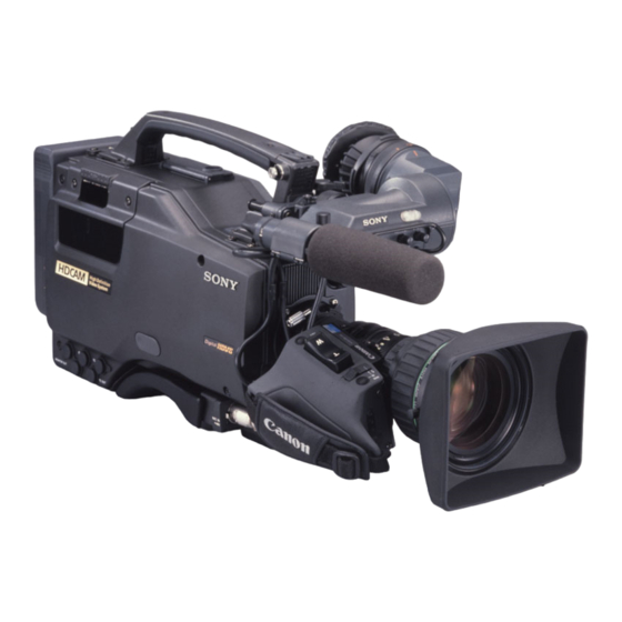
- Page 1 HDCAM CAMCORDER HDW-700A MAINTENANCE MANUAL Part 1 1st Edition Serial No. 10001 and Higher...
- Page 2 ! WARNING This manual is intended for qualified service personnel only. To reduce the risk of electric shock, fire or injury, do not perform any servicing other than that contained in the operating instructions unless you are qualified to do so. Refer all servicing to qualified service personnel.
- Page 3 For the customers in the U.S.A. and Canada CAUTION RECYCLING NICKEL-CADMIUM BATTERIES Danger of explosion if battery is incorrectly replaced. Nickel Cadmium batteries are Replace only with the same or equivalent type recyclable. You can help preserve our recommended by the manufacturer. environment by returning your unwanted Dispose of used batteries according to the batteries to your nearest point for...
-
Page 5: Table Of Contents
http://getMANUAL.com Table of Contents Manual Structure Purpose of this manual ....................5 Related manuals ......................5 Contents ........................6 1. Installation 1-1. Operating Conditions .................. 1-1 1-2. Connectors....................1-1 1-3. Input/Output Signals ................... 1-2 1-4. Settings of Board Switches and Short-circuit Pins ........1-4 1-4-1. - Page 6 4. Setup Menu 4-1. Setup Menu ....................4-1 4-1-1. TOP Menu .................. 4-3 4-1-2. OPERATION Menu ..............4-4 4-1-3. PAINT Menu ................4-9 4-1-4. MAINTENANCE Menu ............4-14 4-1-5. FILE Menu ................4-18 4-1-6. INDEX Menu ................4-19 4-1-7. DIAG DISP Menu ..............4-20 5.
- Page 7 8. Spare Parts 8-1. Notes on Repair Parts .................. 8-1 8-2. Spare Parts List ................... 8-2 9. Overall Block Diagrams 9-1. Camera Block ....................9-1 9-2. VTR Block ....................9-4 HDW-700AE MMP1...
-
Page 9: Manual Structure
This manual is provided information that is premised the parts level service (adjustments, board layouts, schematic diagrams, detailed parts lists and the like.) for this unit. If this manual is required, please contact to your local Sony’s sale/ service office. -
Page 10: Contents
Contents The maintenance manual part 1 is organized by following sections. Section 1 Installation This section is described about the information that is required to install (operating conditions, connection information, initial setting and the like.) and when installing this unit. Section 2 Service Overview This section is described about fundamental information that is required for service... -
Page 11: Installation
. Places exposed to direct sunlight for a long time or near heaters 1-2. Connectors When connecting cables to the connectors during installation or maintenance work, use the following connectors or cables. HDW-700 Connector/Panel indication Matching Connector/Cable Sony Part No. GENLOCK IN TC IN TC OUT BNC Coaxial Connector 1-560-069-11... -
Page 12: Input/Output Signals
1-3. Input/Output Signals 1-3. Input/Output Signals Input GENLOCK IN: 1.0 Vp-p, 75 Z Output 1.0 Vp-p, 75 Z, unbalanced TC IN: 0.5 V to 18 Vp-p, 10 kZ MONITOR OUT: MIC IN +48 V: _60 dBu 1.0 Vp-p, 75 Z TC OUT: _60 dBu/+4 dBu 8 Z, _∞... -
Page 13
1-3. Input/Output Signals BATT IN: 5-pin (Male) VF: 20-pin (Female)
Pin No. Signal Designation Pin No. Signal Designation BATT IN (_) SDA VF IN/OUT BATT ID — BATT REM — LIGHT CONT SCL VF OUT BATT IN (+) COLOR/BW IN —... -
Page 14: Settings Of Board Switches And Short-Circuit Pins
1-4. Settings of Board Switches and Short-circuit Pins 1-4. Settings of Board Switches and Short-circuit Pins 1-4-1. IF-667 Board (Side B) IF-667 Board Switch Switch No. Description Factory setting S1 1 to 4 Factory use 1, 3→ OFF 2, 4→ ON 1-4-2. -
Page 15: Board
http://getMANUAL.com 1-4. Settings of Board Switches and Short-circuit Pins 1-4-3. SV-185 Board (Side A) SV-185 Board Switch Switch No. Description Factory setting S1 1to 4 Factory use HDW-700AE MMP1... - Page 16 1-4. Settings of Board Switches and Short-circuit Pins 1-4-4. TC-97 Board S101 SL401 S103 S152 S531 S531 S403 SL402 S402 S540 S519 S540 S520 (Side B) Switches on TC-97 Board Switch No. Designation Description Factory setting S101 CH-1 FRONT MIC VR Selects whether to adjust the REAR CH-1 audio input signal level by the ON-OFF FRONT MIC VR.
-
Page 17: Hn-243 Board
1-4. Settings of Board Switches and Short-circuit Pins 1-4-5. HN-243 Board CN21 (Side A) (Side B) Switches on HN-243 Board Switch No. Designation Description Factory setting Turns on or off the adjustment mode. : The adjustment mode ON OFF : The adjustment mode OFF Turns on or off the tracking control. -
Page 19: Service Overview
Section 2 Service Overview 2-1. How to clean the head when the head is clogged When the head is Clogged, refer to Section 5, Periodic Maintenance and Inspection for appropriate head-cleaning. HDW-700AE MMP1... -
Page 20: Main Parts Location And Circuit Configuration
2-2. Main Parts Location and Circuit Configuration 2-2. Main Parts Location and Circuit Configuration 2-2-1. PC Board Location HDW-700AE MMP1... - Page 21 2-2. Main Parts Location and Circuit Configuration System Configuration Board Name Circuit Function CCD unit BI-132 (B) CCD block BI-132 (G) CCD block BI-132 (R) CCD block CN-1432 CCD block CN-1757 CCD block DR-383 CCD block DU-19 CCD block NR-67 CCD block PA-204 CCD block...
- Page 22 2-2. Main Parts Location and Circuit Configuration System Configuration Board Name Circuit Function Head CTL-10 CTL head amp CUE-2 CUE head amp HN-243 Harness, Erase head amp, TC head amp CN-1642 Connector board for Camera mic MA-92 Camera mic amp SW-911 VTR S/S switch, Shutter switch, ABB/AWB switch SW-912...
-
Page 23: Location Of Main Mechanical Parts
2-2. Main Parts Location and Circuit Configuration 2-2-2. Location of Main Mechanical Parts 1 2 3 4 5 6 7 8 1 : Tension regulator arm 17 : CUE/TC head 2 : S1 tape guide ( on S slider ) 18 : Manual eject knob 3 : S2 tape guide ( on S slider ) 19 : Threading motor... -
Page 24: Location/Functions Of Sensors
2-2. Main Parts Location and Circuit Configuration 2-2-3. Location/Functions of Sensors (SPARE) HDW-700AE MMP1... - Page 25 http://getMANUAL.com 2-2. Main Parts Location and Circuit Configuration 1 : Temperature Sensor This sensor detects the temperature to perform black correction. 2 : Cassette-in sensor This sensor detects whether a cassett is in. 3 : REC INHIBIT sensor This sensor detects the REC inhibiting plug of the cassette tape. 4 : Tape end sensor This sensor detects the end of the tape running in the forward direction.
-
Page 26: Removal And Installation Of Exterior Parts
2-3. Removal and Installation of Exterior Parts 2-3. Removal and Installation of Exterior Parts Front Lid Loosen the two screws fully and remove the front lid. (Stoppers are provided for these screws.) Outside Panel Screws with stopper 1. Remove the front lid. 2. -
Page 27: Plug-In Board Removal And Installation
2-4. Plug-in Board Removal and Installation 2-4. Plug-in Board Removal and 2. CN-1507 board Installation Pull out the CN-1507 board in the direction of the arrow, as shown. 2-4-1. Removing/Installing the Relay Boards DA-127 board (CN-1506/1507/1457) DPR-98 board The boards are located in front of the AD-145, DPR-98, DA-127, SV-185, and SY-247 boards. -
Page 28: Removing And Installing The Plug-In Board
• Installation Groove of guide rail Plug-in board Clamper Pull ring Use of the following board removing tool is recommended for removing the board from the unit. Board removing tool (Sony Part No.:J-6309-350-A) 2-10 HDW-700AE MMP1... -
Page 29: Cassette Compartment Aseembly Removal And Installation
2-4. Plug-in Board Removal and Installation 2-5. Cassette Compartment Aseembly Removal and Installation 2-5. Cassette Compartment Aseembly Removal Without the Tool Removal and Installation 1. Insert a screwdriver having a small tip into the panel hole on the top of the board, move the tool in the . - Page 30 2-5. Cassette Compart∑ment Aseembly Removal and Installation 3. Move the cam plate (A) on the right side of the Installation cassette compartment in the direction of the arrow with 1. Adjust the position of the joint arm so that the clear- your fingers until it stops.
-
Page 31: Ejecting The Cassette Tape Manually
2-6. Ejecting the Cassette Tape Manually 2-6. Ejecting the Cassette Tape If the foregoing steps cannot be performed, perform the Manually following procedure. 1. Turn off the power switch. 1. Remove the front lid and outside panel. 2. Open the cover of the outside panel as shown. (Refer to section 2-3.) 3. -
Page 32: Fixtures And Measuring Equipment For Adjustment
Mechanism deck extension harness Pin 100 To mechanism deck 3-184-527-01 Cleaning cloth To clean 7-661-018-18 Oil (NT-68) To lubricate 7-651-000-11 Sony grease (SGL-801) 7-700-736-05 Hexagon wrench (d=1.5 mm) To remove screw 7-700-736-06 Hexagon wrench (d=0.89 mm) 8-960-076-01 Alignment tape HR5-1A To adjust audio/video... - Page 33 2-7. Fixtures and Measuring Equipment for Adjustment 2-15 HDW-700AE MMP1...
-
Page 34: Measuring Equipment
Audio Level Meter HEWLETT PACKARD HP3400A Low Frequency Oscillator HEWLETT PACKARD HP8904 Frequency Counter ADVANTEST TR5821AK Digital Voltmeter ADVANTEST TR6845 Black and White Monitor SONY HDM-14E5 (for NTSC) (Horizontal resolution more than 900) Color Monitor 2-16 HDW-700AE MMP1... -
Page 35: Error Code And Error Message
http://getMANUAL.com Section 3 Error Code and Error Message 3-1. Error Code OVER EMPH OVER DIAG PB VITC NDF EXT-LK HOLD Error code TAPE BATT ∞ Warning indicators SERVO HUMID SLACK PEAK dB LCD display screen WARNING INDICATORS The warning indicators on the LCD display screen light when a fault occurs during the power-on-sequence or normal operation. -
Page 36: Error Message
3-2. Error Message 3-2. Error Message The error message is superimposed on the viewfinder screen when faults occur during the power-on sequence or normal operations. Error Message Operation Remedy ? (Blinking) During power-on sequence A fault has been detected in the camera or VTR (HUMID or SLACK). -
Page 37: Setup Menu
Section 4 Setup Menu 4-1. Setup Menu The setup menu is used for selecting various setting values, items displayed on the viewfinder screen, the method of displaying, and adjustments. The menu is displayed on the viewfinder screen. The menu can also be displayed by the signals from the MONITOR OUT connector. - Page 38 4-1. Setup Menu Switches VF DISP switch : Displays characters and messages indicating the settings and operating status of the unit on the viewfinder screen. : Turns off all the displays on the viewfinder screen. MENU : Displays the setup menu on the viewfinder screen. MIC/MENU knob Selects the items displayed on the viewfinder screen and changes settings.
-
Page 39: Top Menu
4-1. Setup Menu 4-1-1. TOP Menu TOP MENU * TOP MENU * OPERATION PAINT MAINTENANCE FILE INDEX DIAG DISP Menu Description OPERATION Consists of operation items such as those to be set by a camera operator according to the conditions of the subject to be shot. PAINT Consists of general paint operation items such as white. -
Page 40: Operation Menu
4-1. Setup Menu 4-1-2. OPERATION Menu CONTENTS2.VF DISPLAY 3.´!´ LED 4.MARKER 5.GAIN SW 6.VF SETUP 7.AUTO IRIS 8.BATTERY/D56 9.OPERATOR FILE Item Description 2. VF DISPLAY Searching function for pages of the operation menu. 3. ‘!’ LED 4. MARKER 5. -
Page 41
4-1. Setup Menu VF DISPLAY
CAM ID: ZOOM VOLT SHUTT : IRIS FILTER: D5600K: WHITE : GAIN TAPE AUDIO : Item Setting Description ON, OFF Sets the extender display to ON or OFF. ZOOM ON, OFF Sets the zoom position display to ON or OFF. SHUTT ON, OFF Sets the shutter speed/mode/reading mode display to ON or OFF. -
Page 42
4-1. Setup Menu MARKER
CENTER CENTER SEL SAFETY ZONE : SAFETY AREA : 4:3 FRAME : OFF 4:3 MOD : OFF 4:3 MOD LVL : EFFECT AREA : Item Setting Description CENTER ON, OFF Sets the center marker display to ON or OFF. CENTER SEL 1, 2, 3, 4 Sets the center marker type... -
Page 43
4-1. Setup Menu VF SETUP
ZEBRA : OFF : 70% ZEBRA1(70%) : 128 ZEBRA2(100%): 128 VF SCAN : 16:9 Item Setting Description ZEBRA ON, OFF Sets the zebra display to ON or OFF. 70 %, 100 %, 70 & 100 % Sets the zebra type. -
Page 44
4-1. Setup Menu BATTERY/D56
BATT TYPE : LITHIUM BEFORE END: 11.5V : 11.0V D5600K : OFF Item Setting Description BATT TYPE ANTON, BP-90A, Selects the battery type. LITHIUM, OTHERS BEFORE END 10.0 to 16.0 V Displays the alarm voltage indicating that the battery is wearing out. 10.0 to 16.0 V Displays the alarm voltage indicating that the battery has worn out. -
Page 45: Paint Menu
http://getMANUAL.com 4-1. Setup Menu 4-1-3. PAINT Menu SW STATUSFLARE GAMMA BLACK GAMMA : OFF KNEE WHITE CLIP DETAIL LEVEL DEPEND: MATRIX Item Setting Description FLARE ON, OFF Sets the flare correction circuit to ON or OFF. GAMMA ON, OFF Sets the gamma correction function to ON or OFF. -
Page 46
4-1. Setup Menu GAMMA
[R] [G] [B] [M] GAMMA BLK GAM: COARSE : 0.45 GAMMA BLACK GAMMA : OFF TEST : OFF Item Setting Description GAMMA _99 to 99 Adjusts the gamma correction curve of the R,G,B master. R/G/B/M BLK GAM _99 to 99 Adjusts the black gamma of the R,G,B master. -
Page 47
4-1. Setup Menu DETAIL 1
DETAIL LEVEL LIMITER CRISPENING H/V RATIO FREQUENCY LEVEL DEPEND: Item Setting Description DETAIL ON, OFF Sets the function for attaching the detail signal for improving the resolution to ON or OFF. LEVEL _99 to 99 Sets the general level of the detail signal. -
Page 48
4-1. Setup Menu MATRIX
[-R] [-G] [-B] MATRIX USER MTX PRESET MTX : OFF PRE MTX SEL : SMPTE-240M TEST : OFF Item Setting Description R-G, R-B, _99 to 99 Sets the linear matrix coefficient of R-G, R-B, G-R, G-B, B-R, G-R, G-B, _99 to 99 and B-G respectively. -
Page 49
4-1. Setup Menu SCENE FILE
[FILE STORE] STANDARD Item Setting Description Saves and Calls the scene file. How to save 1. Set “→” to FILE STORE and press the MIC/MENU knob to blink [FILE STORE]. 2. Select the file number (1-5) for saving. FILE STORE (If data is already saved, the data will be replaced with new one.) How to call... -
Page 50: Maintenance Menu
4-1. Setup Menu 4-1-4. MAINTENANCE Menu AUTO SETUPAUTO BLACK AUTO WHITE AUTO LEVEL TEST : OFF Item Setting Description AUTO BLACK Press the MIC/MENU Starts the automatic black balance adjustment. knob to execute the (Pressing the MIC/MENU knob during the execution cancels the execution.) operation. -
Page 51
4-1. Setup Menu BLACK SHADING
[R] [G] [B] [M] V SAW V PARA : H SAW H PARA : BLK SET: BLACK MASTER GAIN : BLK SHADING : Item Setting Description V SAW R/G/B _99 to 99 Adjusts the black shading V SAW correction amount of the R,G,B master. V PARA R/G/B _99 to 99 Adjusts the black shading V PARA correction amount of R,G,B. -
Page 52
4-1. Setup Menu VTR SETUP
FF/REW AUDIO: PB AUDIO CH : 1/2 AU REC CH3/4: AU REC 1KHz : MUTE AU EMPHASIS : TC OUT : TCG/PB TC SAVE MODE: OFF CTL TIMER REAL TIME : AUTO Item Setting Description FF/REW AUDIO... -
Page 53
4-1. Setup Menu CAMERA ID
CAMERA ID : HDW-700 CAMERA ID : ON & ´[]*+,-./0123456789:; <=>?@ABCDEFGHIJKLMNOPQRS TUVWXYZ[¥] Space Item Setting Description CAMERA ID Sets camera ID of 10 or less characters consisting of alphabets, numerals, symbols and spaces. CAMERA ID ON, OFF Sets the camera ID display to ON or OFF. -
Page 54: File Menu
4-1. Setup Menu 4-1-5. FILE Menu REFERENCE FILESTORE FILE CLEAR FILE 10SEC CLEAR: OFF Item Setting Description STORE FILE Press the MIC/MENU Registers the adjustment values of each item as the reference value. knob to execute the (Pressing the MIC/MENU knob makes FILE STORE OK? blink. -
Page 55: Index Menu
http://getMANUAL.com 4-1. Setup Menu 4-1-6. INDEX Menu INDEX PAGE INDEX PAGE: 1 ´!´ LED 4:3 FRAME 4:3 MODULATION 59.94-60Hz(VF DISP) APL RATIO AUDIO(VF DISP) AU-EMPHASIS AU-REC 1KHz AU-REC CH3/4 Item Description INDEX PAGE Searches for each item. (Rotate the MIC/MENU knob and select INDEX PAGE. Then set the “→” mark to the item required, and press the MIC/MENU knob to execute the operation.) 4-19... -
Page 56: Diag Disp Menu
4-1. Setup Menu 4-1-7. DIAG DISP Menu HOURS METERDRUM RUNNING: XXXXXXH TAPE TRAVEL : XXXXXXH OPERATION : XXXXXXH THREADING : XXXXXX Item Setting Description DRUM RUNNING XXXXXXH Displays the drum running time. TAPE TRAVEL XXXXXXH Displays the tape running time. OPERATION XXXXXXH Displays the operating time. -
Page 57
4-1. Setup Menu ROM VERSION
IF BOARD : 1.00 SY BOARD : 1.00 SV BOARD : 1.00 TC BOARD : 1.00 Item Setting Description IF BOARD X.XX Displays the ROM version of the IF board. SY BOARD X.XX Displays the ROM version of the SY board. -
Page 58
4-1. Setup Menu SERVO ADJ
CAPS SPEED : XXXX DRUM PHASE : XXXX CAPS FG : XXXX SLACK : XXXX : XXXX : XXXX : XXXX Item Setting Description CAPS SPEED XXXX Displays the capstan free speed adjustment data. DRUM PHASE XXXX Displays the drum PG phase adjustment data. -
Page 59: File System
Section 5 File System The HDW-700A is equipped with various file systems for managing data. 5-1. File Structure The following five types of files are available. 1. Operator File Stores the items displayed on the viewfinder and switch settings for camera operator. This file can be stored in the setup card, but video data (paint data) cannot be stored. -
Page 60: Operator File
5-2. Operator File 5-2. Operator File Data is stored at the setting menu. The items which can be stored are indicated with in “Operator” of “File Store” column in Section 5-8. File Items. (Except the items of D5600K and Auto Iris Override.) Storing method (Step 1 of Fig. -
Page 61: Preset Operator File
5-3. Preset Operator File 5-3. Preset Operator File The operator file items can be reset to the preset values. There are two ways of calling-calling from the setting menus or reading at power ON. The items which can be stored on file are the same as Operator File. -
Page 62: Registering Reference Files
5-4. Registering Reference Files 5-4. Registering Reference Files This file can be stored and read using the setting menu or the Remote Control Panel of MSU-700, etc. Only one file can be stored, and will be stored in the camera and setup card. The item which can be stored is indicated with in “Reference”... - Page 63 5-4. Registering Reference Files Reading the Reference File Data from the Setup Card (Steps 2 and 3 of Fig. 5-3.) During the file storing, read the reference files which have been stored in the setup card at the same time. The reference files in the camera can also be changed.
-
Page 64: Registering The Lens File
5-5. Registering the Lens File 5-5. Registering the Lens File The white shading which occurs when the extender is turned on, flare balance, white balance, F value of the open edge of the lens, name, etc. can be stored. Five files can be stored. When using several lenses, store the adjustment data on lens replacement in the file to eliminate the need for adjustments each time the lens is replaced. - Page 65 http://getMANUAL.com 5-5. Registering the Lens File Adjusting Using the Second Lens (1) Mount the lens. Set the setting menus as follows. [FILE] → [LENS|FILE] → [FILE], and select the number between “2” to “5”. (2) Set the lens file name and F value of the open edge of the lens. (3) Set the extender to OFF.
-
Page 66: Registering The Scene File
5-6. Registering the Scene File 5-6. Registering the Scene File The scene file is used for storing temporary video adjustment values according to the scene. 5 files can be stored and the data will be stored in the camera. The data can be stored using a setting menu or the Remote Control Panel of MSU-700, etc. -
Page 67: Adjusting The Nd Offset
5-7. Adjusting the ND Offset 5-7. Adjusting the ND Offset The white balance may be slightly deviated in the ND filters. In such cases, adjust the offset. Taking the ND1 white balance as the reference, the ND offset stores the deviation of the white balance of ND:2, 3, and 4. -
Page 68: File Items (After If Board Rom Version 2.00 And Higher)
VTR AU REC 1KHz MUTE VTR TC OUT TCG/PB VTR CTL TIMER VTR REAL TIME AUTO H phase (When GEN LOCK) Camera ID HDW-700A Lens open F value (F STOP) Monitor out level Monitor out level (Pb/Pr) 5-10 HDW-700AE MMP1... - Page 69 5-8. File Items (After IF Board ROM Version 2.00 and Higher) File Store When Type Item Operator Refe Scene Lens Standard Power is At Factory-set turned ON -rence EX OFF EX ON ON/OFF VF DISP related (Extender, zoom, shutter, iris, D5600K, tape remainder, audio input level, TC, camera ID,...
- Page 70 5-8. File Items (After IF Board ROM Version 2.00 and Higher) File Store When Type Item Operator Refe Scene Lens Standard Power is At Factory-set turned ON -rence EX OFF EX ON ON/OFF Auto iris Iris close Test 1 (VA SAW) Test 2 (PR SAW) Color bar D5600K...
- Page 71 5-8. File Items (After IF Board ROM Version 2.00 and Higher) File Store When Type Item Operator Refe Scene Lens Standard Power is At Factory-set turned ON -rence EX OFF EX ON Control (Analog) Zebra 70% level (Analog) Zebra 100% level (Analog) 4:3/VISTA mask level (Analog) White R/B REF +LENS...
- Page 72 5-8. File Items (After IF Board ROM Version 2.00 and Higher) File Store When Type Item Operator Refe Scene Lens Standard Power is At Factory-set -rence turned ON EX OFF EX ON Control (Digital) Black gamma (*5) REF (0) Master (Digital) Black gamma REF (0)
- Page 73 5-8. File Items (After IF Board ROM Version 2.00 and Higher) “ ” means items which will be displayed as 0. “ ” means that the values stored will be continue to be displayed even after they have been stored. The “...
-
Page 75: Diagnostic Mode
http://getMANUAL.com Section 6 Diagnostic Mode The DIAGNOSTIC mode is used for checking the VTR. Use this mode with the tape stopped. Switches 3. SHIFT button 2. ADVANCE button CH-1 CH-2 LEVEL ADVANCE SHIFT PRESET AUTO F-RUN MANUAL R-RUN AUDIO SELECT REGEN AUDIO IN 1. - Page 76 6. Diagnostic Mode MODE DESCRIPTION LCD SCREEN HOURS METER The following are displayed. 1. Drum running meter (Cumulative) 2. Tape running meter (Cumulative) 3. Operation meter (Cumulative) 4. Threading counter (Cumulative) 5. Drum running meter (Resetable) 6. Tape running meter (Resetable) 7.
-
Page 77: Periodic Maintenance And Inspection
Section 7 Periodic Maintenance and Inspection 7-1. Cleaning Make it a rule to clean the unit periodically to assure that the unit functions and performs at its best for the longest-possible product-life period. 7-1-1. General Information on Cleaning 1. Index Tape cleaner (section 7-1-5) CTL head... - Page 78 7-1. Cleaning 2. Notes . Be sure to turn the power off before cleaning. . The mechanical deck blocks consist of precision parts, and are fabricated and adjusted precisely. Do not damage the parts nor apply excessive force during cleaning. .
-
Page 79: Cleaning Of Tape Running Surface Of Upper Drum And Video Heads
7-1. Cleaning 7-1-2. Cleaning of Tape Running Surface of Upper Drum and Video Heads The video head and upper drum may damage easily. Be careful not to damage them when cleaning. Tools . Cleaning cloth : 3-184-527-01 . Cleaning fluid : 9-919-573-01 Never use a cotton swab. -
Page 80: Cleaning Of Tape Running Surface Of Lower Drum And Lead Surface
7-1. Cleaning 7-1-3. Cleaning of Tape Running Surface of Lower Drum and Lead Surface Be careful not to damage the lower drum (especially the lead surface) when cleaning. Also clean the upper edges of the lower drum carefully because they are near the video heads. Tools . -
Page 81: Cleaning Of Stationary Heads
7-1. Cleaning 7-1-4. Cleaning of Stationary Heads Be careful not to damage the surfaces of the stationary heads when cleaning. Tools . Cleaning cloth : 3-184-527-01 . Cleaning fluid : 9-919-573-01 Procedure 1. Clean the tape running surfaces (shaded portion) of the FE, CTL, CUE/TC heads by wiping them in the vertical direction using a cleaning cloth moistened with cleaning fluid. -
Page 82: Cleaning Of Tape Path System And Tape Cleaner
7-1. Cleaning 7-1-5. Cleaning of Tape Path System and Tape Cleaner The edge of the tape cleaner is very sharp and may hurt your fingers. Avoid touching the edge when cleaning. Tools . Cleaning cloth : 3-184-527-01 . Cleaning fluid : 9-919-573-01 Procedure 1. -
Page 83: Cleaning Of Filter
7-1. Cleaning 7-1-6. Cleaning of Filter Clean the dust-filter periodically once every 2 or 3 months. Otherwise, clogging of dusts, etc. may cause the temperature inside the unit to rise and result in malfunctions. Removal 1. Remove the four precision screws (P2 x 5, P2 x 10) and remove covers. 2. -
Page 84: Maintenance After Use In Special Environments
5. Clean the connector pin of the connector panel. 6. Perform general operations (recording, playback, etc.) and verify that no abnormal noises are pro- duced from the unit and that the unit operates normally. If operations are found abnormal, etc., contact Sony service personnel. HDW-700AE MMP1... -
Page 85: Periodic Inspections
http://getMANUAL.com 7-3. Periodic Inspections 7-3. Periodic Inspections Make it a rule to carry out periodic inspections to assure that the unit functions and performs at its best for the longest-possible product-life period. 7-3-1. Hours Meter The unit can display a hours meter on its LCD display at the side panel. The hours meter is resetable. It is recommended that periodic inspection be carried out using this hours meter. -
Page 86: Periodic Inspection List
7-3. Periodic Inspections 7-3-2. Periodic Inspection List The parts with the marking “↓” (1 to 3) are included in the part listed immediately below (4). MODE A : DRUM RUNNING METER MODE B : TAPE RUNNING METER : Check : Replacement Inspection Hours (H) Replacement Part Item... - Page 87 7-3. Periodic Inspections 7-11 HDW-700AE MMP1...
-
Page 89: Spare Parts
Therefore, specified parts should be used in the case of replacement. 2. Standardization of Parts Some repair parts supplied by Sony differ from those used for the unit. These are because of parts commonal- ity and improvement. Parts list has the present standardized repair parts. -
Page 90: Spare Parts List
8-2. Spare Parts List Plug-in Board Part No. SP Description Mechanical Block A-8316-492-A o MOUNTED CIRCUIT BOARD, EN-134 A-8316-493-A o MOUNTED CIRCUIT BOARD, ENC-44 Part No. SP Description A-8316-494-A o MOUNTED CIRCUIT BOARD, DEC-95 A-8316-495-A o MOUNTED CIRCUIT BOARD, VN-11 A-8316-736-A s DRUM ASSY DHH-04A-R A-8316-497-A o MOUNTED CIRCUIT BOARD, SY-247 A-8316-738-A s UPPER DRUM ASSY DHR-04-R... -
Page 91: Overall Block Diagrams
Overall Block Diagram Section 9 Overall Block Diagrams 9-1. Camera Block CCD BLOCK NR-67 PA-204 SH-73 B CCD CORRELATED VIDEO DOUBLE TO CAMERA BLOCK SAMPLING B GAIN BI-132(G) G CCD G CCD CORRELATED VIDEO VIDEO DOUBLE TO CAMERA BLOCK IMAGER SAMPLING G GAIN R CCD... - Page 92 Overall Block Diagram MB-743 CN-1432 VA-180 AD-145 CN-1506 DIFFER B DA VIDEO POST GAIN UP WHT BAL B VA VIDEO B VA VIDEO FROM CCD BLOCK ENTIAL FLARE PRE KNEE B VIDEO FILTER WHT SHAD DIFFER G DA VIDEO POST GAIN UP WHT BAL G VA VIDEO...
- Page 93 Overall Block Diagram DPR-98 TO,FRM VTR DA-127 VDA-40 DRIVE RET Y CHARACTER PB Y POST FILTER RET Pr VF OUT TO VIEW POST FINDER Y/PB Y FILTER PB Pr C/PB C PB Pb RET1 POST FILTER ZEBRA DETECT CN-1507 MONITOR OUT SYNC CHARACTER SG-255...
-
Page 94: Vtr Block
Overall Block Diagram 9-2. VTR Block PB VIDEO REC VIDEO FROM/TO CAMERA CAM F CAM H REF-F1/2/3/4 BLOCK 74.25MHz VTR TG 46.4MHz 64FS 256FS EN-134 16M SDRAM CONCEAL CAMERA MIC IN 46.4MHz VN-11 CN-1642 MA-92 CN-1482 CA EN CUE REC REAR CH-1 IN 64FS INPUT SEL... - Page 95 http://getMANUAL.com Overall Block Diagram REC A/E SEL PB A/E SEL 16M SDRAM REC INHIBIT PB B/F SEL DRUM TEST PB C/G SEL PB D/H SEL REC AMP SYNC HENC-A BRR ENC 16M SDRAM 46.4MHz ECC ENC MPXO DATA 16M SDRAM MPX CK 46.4MHz SYNC...
- Page 97 The material contained in this manual consists of information that is the property of Sony Corporation and is intended solely for use by the purchasers of the equipment described in this manual. Sony Corporation expressly prohibits the duplication of any portion of this manual or the use thereof for any...
- Page 98 Printed in Japan Sony Corporation HDW-700A (UC) E 1999. 1 08 Broadcasting & Professional Systems Company 3-201-478-01 ©1999...