
Related Manuals for Daikin SUT Series


Summary of Contents for Daikin SUT Series
- Page 1 SE-04753 [Operation Manual] 2/49 Hybrid Hydraulic System [Super Unit] SUT03S15L07-10-F SUT03S30L07-10-F SUT SERIES Operation Manual DAIKIN INDUSTRIES, LTD. Oil Hydraulics Division...
- Page 2 The latest version of this manual is available through DAIKIN Oil Hydraulics Division Internet Service (DHCnet HomePage) (http:// www.dhcnet.daikin.co.jp:8100/). This operation manual should be used as a reference that provides safety instructions for DAIKIN Hydraulic Unit. In addition to this manual, please prepare safety references for your machine to ensure safe operations and maintenance in accordance with various standards and norms.
- Page 3 DAIKIN shall not be responsible for any damage attributable to a fire, earthquake, third party’s action and other accidents, as well as customer’s intention, misuse or use under abnormal conditions. DAIKIN shall not be responsible for any damage incidental to use of this product or impossibility to use this product (loss of business profit, discontinuation of business).
-
Page 4: Table Of Contents
[12. Maintenance] ......................35 to 40 Periodic inspection Cleaning and replacement Oil cooler maintenance procedure Oil filling port (air breather) maintenance procedure Suction strainer maintenance procedure [Attachment: Safety Valve Adjusting Procedure]..............41 [Attachment: Power-ON External I/O Signal Timing Chart]..........42 to 48 DAIKIN INDUSTRIES, LTD. -
Page 5: [1. Introduction]
IPM Motor Drive Hydraulic Unitprovides overwhelmingly excellent energy conservation performance and advanced functions. Before using the SUT Series , please read this manual thoroughly, and handle and maintain this unit properly, so that this unit can retain excellent performance for a long period. -
Page 6: [3. Description On Model Identification Code]
[Operation Manual] 6/49 [3. Description on Model Identification Code] ****** (a) Series name (e) Maximum operating pressure SUT: SUT series 07: 7.0 MPa (b) Tank capacity (f) Design No. 03: 30 L Advances according to model change. (c) Pump type... -
Page 7: [4. Specifications And Operating Conditions]
Operating conditions Dedicated mineral hydraulic oil / Wear-resistant hydraulic oil (Note 3) Hydraulic oil (For recommended brands, see DAIKIN “Hydraulic Equipment General Catalog (HK196)”.) Viscosity grade: ISO VG 32 to 68 Viscosity range: 15 to 400 mm Pollution degree: NAS Class 9 or lower level... -
Page 8: [5. Precautions For Use]
Procedure” on p. 41. For protection of peripheral equipment (actuator, pressure gauge, etc.) of the master machine, it is recommended that the safety valve pressure setting should be “Unit pressure setting + 0.5 MPa” in order to suppress surge pressure. DAIKIN INDUSTRIES, LTD. -
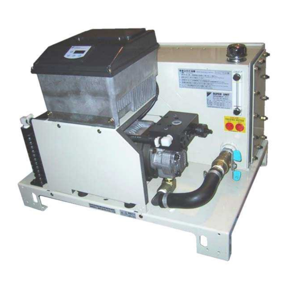
Page 9: [6. Names Of Unit Components]
Stop valve Discharge port (Rc3/8) Operation panel ControllerTank Oil level gauge Safety precaution Oil cooler nameplate Unit nameplate Safety valve black Bolt Transport nameplate nameplate Motor Hydraulic pump DAIKIN INDUSTRIES, LTD. -
Page 10: [7. Hydraulic Circuit]
Hydraulic circuit diagram Rc3/8 Rc3/4 Above the oil surface Hose Hose Hose Rc1/2 Components Part No. Name Tank Suction strainer Stop valve Oil level gauge Oil filling port (Air breather) Controller Inverter drive pump Oil cooler DAIKIN INDUSTRIES, LTD. -
Page 11: Piping
This hydraulic unit incorporates a check valve. If an additional inline check valve is mounted to the discharge port, resonance occurs, which may have bad influence on the master machine. Therefore, do not use an inline check valve. DAIKIN INDUSTRIES, LTD. -
Page 12: [8. Precautions For Operation, Transportation And Installation]
(This may cause oil leak, or malfunction due to air intrusion.) During transportation, hold the hydraulic unit securely so that it will not be moved by vibration or external force.(Hydraulic oil is not included) Model SUT03S15L07 SUT03S30L07 Weight 65 kg 67 kg DAIKIN INDUSTRIES, LTD. -
Page 13: Precautions For Installation
If the hydraulic unit is installed on an inclined plane, oil leak or air intrusion occurs, resulting in abnormal sound or shortened service life of the equipment. Be sure to install the unit on a level plane. DAIKIN INDUSTRIES, LTD. -
Page 14: [9. Preparations For Operation]
[4] The oil level in the tank may largely fluctuate depending on the machine hydraulic circuit. This may result in oil leak from the tank, or decrease in oil level. DAIKIN INDUSTRIES, LTD. -
Page 15: Electric Wiring
The hydraulic unit incorporates an overcurrent protection function. Therefore, it does not need an overcurrent protection thermal relay. [Rated current and breaker setting] Power supply voltage and frequency Model Breaker setting 3 200V 50Hz 3 200V 60Hz 3 220V 60Hz SUT03S15L07 SUT03S30L07 10.9 10.7 DAIKIN INDUSTRIES, LTD. - Page 16 Before removing the controller cover, be sure to leave the controller for at least five minutes to discharge electricity from the capacitor. [2] Before turning ON the power supply to start operation, mount all controller covers. DAIKIN INDUSTRIES, LTD.
- Page 17 Tighten the tightening cap to fasten the cable. The cable sheath protrusion length should be approx. 2 to 3 mm. Controller fastening screw Wiring hole Controller fastening screw Tightening cap Sheath protrusion length: 2 to 3 mm DAIKIN INDUSTRIES, LTD.
- Page 18 SUT03S15L07 2.5 mm or more CE362 2.5 mm x 4 cores TMEV-2-4 (manufactured by (AWG14 or larger size) (manufactured by KURAMO) (manufactured by NICHIFU) SUT03S30L07 OHM ELECTRIC) * For the power supply cable, use the 2451EC/H05RR-F cable. DAIKIN INDUSTRIES, LTD.
- Page 19 If the crimp tool is not suitable for the crimp terminal, the cable will come off the terminal due to a crimp failure during operation. This results in short-circuiting or burnout of the circuit caused by abnormal heating. DAIKIN INDUSTRIES, LTD.
- Page 20 [3] Tighten the screw with a screwdriver. [4] Pull the cable lightly to make sure that it is securely connected. Unsheathed length of the cable: 6 mm Procedure for connecting the cable to the terminal block DAIKIN INDUSTRIES, LTD.
-
Page 21: I/O Signal Cable Specifications
Contract output a (When the alarm output combination setting [P08] is “0”) Contract output b Contract output common These terminals are not open to users. Do not use these terminals. No connectionDAIKIN INDUSTRIES, LTD. - Page 22 Power cannot be supplied from this controller to external equipment. The current flowing through each input circuit is 5 mA (typical). To configure a circuit with a contact, be careful about the minimum current of the contact. DAIKIN INDUSTRIES, LTD.
- Page 23 This value varies depending on switching frequency and environmental conditions. We recommend you to check the minimum allowable load in actual conditions. To drive induction load, take surge preventive measures. DAIKIN INDUSTRIES, LTD.
-
Page 24: [10. Test Run]
Evacuate air from the hydraulic circuit completely. If air is not completely evacuated, the following phenomena may occur. [1] Abnormal operation of cylinder actuator [2] Abnormal sound of pump and valve DANGER When evacuating air, high-pressure and high-temperature oil may spout out. Pay attention to oil splash. DAIKIN INDUSTRIES, LTD. -
Page 25: [11. Operation Panel Operating Procedure]
Key switch operations for shift between individual modes are shown below: Power-ON Normal mode Keep pressing simultaneously for at least two seconds. Press Press Press Press Keep pressing simultaneously for at least two seconds. Monitor mode Setting mode Alarm mode DAIKIN INDUSTRIES, LTD. -
Page 26: Operating Procedure For Each Mode
The indication label should be prepared by the user. Note 2) For details on the alarm codes, refer to description on the alarm display mode. You can check the current power-ON count by pressing the key when an alarm code is displayed. DAIKIN INDUSTRIES, LTD. - Page 27 Press the key three times. Blinking Monitor display Discharge rate (theoretical value) 3.6 L/min Return to actual pressure display mode To monitor other parameter, return to the actual pressure display mode once, and then select a desired item. DAIKIN INDUSTRIES, LTD.
-
Page 28: B) Setting Mode
For the initial values and adjusting ranges of non-standard models or custom-made models, see the delivery specifications on separate sheets. NOTE: [1] The above discharge rate set value is a theoretical value (the product of theoretical displacement volume by rpm). It is slightly different from the actual discharge rate. DAIKIN INDUSTRIES, LTD. - Page 29 : Decreases in both pressure and speed (flow rate) are simultaneously specified. Normally, the P05, P10 and P11 settings need not to be changed. However, if a special circuit condition (large load volume, etc.) is expected, these settings must be changed. DAIKIN INDUSTRIES, LTD.
- Page 30 Changing set value Writing set value Return to actual pressure display mode CAUTION: The flow rate setting can be arbitrarily specified in steps of 0.1 L/min. Theoretical pump displacement volume (cc/rev) Model SUT03S15L07 SUT03S30L07 DAIKIN INDUSTRIES, LTD.
- Page 31 Parameter No. selection P-Q selection 1 Set value display Displays pressure set value for P-Q selection 1 Changing set value Writing set value Return to actual pressure display mode (When “P-Q selection 1” is selected) DAIKIN INDUSTRIES, LTD.
- Page 32 Note 6 Specify whether to activate the contact outputs (alarm, warning and pressure switch outputs) individually, or integrate them into one output. Note 7 1: Enables reset to factory settings. When the power supply is turned ON again, the factory settings become active. DAIKIN INDUSTRIES, LTD.
-
Page 33: C) Alarm Mode
Alarm No. and erroneous Operation stop Power-ON parameter No. are alternately (during initialization) displayed. See the table on the next page. Warning No. and actual Normal operation pressure value are alternately Operation displayed. continued Normal operation Warning No. display DAIKIN INDUSTRIES, LTD. - Page 34 * The alarm/warning output of the individual alarm output of Classification [3], and the relay output B contact of the integrated alarm output vary depending on the warning output level setting [P07]. See “Attachment: Power-ON External I/O Signal Timing Chart”. DAIKIN INDUSTRIES, LTD.
-
Page 35: [12. Maintenance]
[2] Measure the insulation resistance, and check for a decrease in insulation resistance. [3] Make sure that the ground cable is securely connected. Hose Yearly Check the hose for cracks, fracture or flaws. Screws and pipes Daily, Occasionally Check screws and pipes for looseness and oil leak. DAIKIN INDUSTRIES, LTD. -
Page 36: Cleaning And Replacement
Before removing the controller cover, be sure to leave the controller for at least five minutes to discharge electricity from the capacitor. [3] Before turning ON the power supply to start operation, mount all covers to the controller. DAIKIN INDUSTRIES, LTD. -
Page 37: Oil Cooler Maintenance Procedure
[3] Remove the hexagon socket head bolts Bolt Transport nameplate nameplate (M5 x L16: 2 pieces) with washers, and dismount the oil cooler. Hose bands Hexagon socket head bolts (M5 x L16: 2 pieces) with washersDAIKIN INDUSTRIES, LTD. - Page 38 After cleaning is completed, reassemble the oil cooler. After reassembling is completed, conduct the test run procedure described on p. 24 to make sure that the hydraulic unit normally operates. Check if the oil cooler air intake/exhaust direction is correct. (See p. 13) DAIKIN INDUSTRIES, LTD.
-
Page 39: Oil Filling Port (Air Breather) Maintenance Procedure
StrainerMounting direction Mount the cap by turning it clockwise by hand until it stops. WARNING During air blow, wear protective goggles to prevent accumulated substances or dust from touching your eyes. DAIKIN INDUSTRIES, LTD. -
Page 40: Suction Strainer Maintenance Procedure
After reassembling is completed, conduct the test run procedure described on p. 24 to make sure that the hydraulic unit normally operates. WARNING During air blow, wear protective goggles to prevent accumulated substances or dust from touching your eyes. DAIKIN INDUSTRIES, LTD. -
Page 41: [Attachment: Safety Valve Adjusting Procedure]
(When tightening the lock nut, be careful not to allow the adjusting screw to turn.) Pressure adjusting screw length (Reference) Pressure adjusting screw length Lock nut (MPa)Pressure adjusting screw length (mm) DAIKIN INDUSTRIES, LTD. -
Page 42: [Attachment: Power-On External I/O Signal Timing Chart]
Pressure Magnetic pole Mode Standby for operation Normal control Charging detection Display Actual pressure display * Magnetic pole detection will be executed at the first motor startup after power-ON. DAIKIN INDUSTRIES, LTD. - Page 43 Mode Controlled in warning status Normal control H: Actual pressure Display Actual pressure display L: Alarm code display * Alternately displayed at 1 second interval. * When “Level 0” is selected, an actual pressure value is displayed. DAIKIN INDUSTRIES, LTD.
- Page 44 Note) For the purpose of explanation, the above “1-7 Alarm classification [4]” chart shows the case where the pressure switch is activated without a dead zone. Actually, however, the pressure switch has a dead zone of approx. 0.5 MPa. DAIKIN INDUSTRIES, LTD.
- Page 45 0.2 sec. average 3 sec. max. Pressure Magnetic pole Mode Normal control Standby for operation Charging detection Display Actual pressure display * Magnetic pole detection will be executed at the first motor startup after power-ON. DAIKIN INDUSTRIES, LTD.
- Page 46 Mode Controlled in warning status Normal control L: Alarm code H: Actual pressure Display Actual pressure display display * Alternately displayed at 1 second interval. * When “Level 0” is selected, an actual pressure value is displayed. DAIKIN INDUSTRIES, LTD.
- Page 47 Note) For the purpose of explanation, the above “2-7 Alarm classification [4]” chart shows the case where the pressure switch is activated without a dead zone. Actually, however, the pressure switch has a dead zone of approx. 0.5 MPa. DAIKIN INDUSTRIES, LTD.
- Page 48 When the command value is being changed according to a change in P-Q selection No., the complete signal status is “Lo”. When the command value does not change any more, the complete signal status is changed to “Hi”. DAIKIN INDUSTRIES, LTD.