
Related Manuals for GE Bently Nevada 3300/03


Summary of Contents for GE Bently Nevada 3300/03
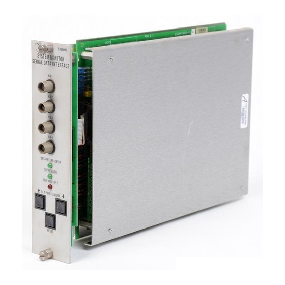
- Page 1 Operation Manual Bently Nevada™ Asset Condition Monitoring 3300/03 System Monitor Part Number 89604-01 Rev. F (08/07)
- Page 2 Dynamic Data Manager, Keyphasor, Proximitor and Transient Data Manager Contact Information The following ways of contacting Bently Nevada are provided for those times when you cannot contact your local representative: Mailing Address 1631 Bently Parkway South Minden, Nevada USA 89423 Telephone 1.775.782.3611 1.800.227.5514 1.775.215.2873 Internet www.ge-energy.com/bently...
- Page 3 Additional Information Notice: This manual does not contain all the information required to operate and maintain the product. Refer to the following manuals for other required information. 3300 System Overview (Part Number 80171-01) 3300 System Installation Instructions (Part Number 80172-01) 3300 System Troubleshooting (Part Number 80173-01) 3300/12 Power Supply (Part Number 89602-01) Serial Data Interface &...
-
Page 4: Table Of Contents
3300/03 System Monitor Operation Manual Contents SYSTEM MONITOR ............................1 MONITOR FUNCTIONS..........................2 ASSEMBLY & DISASSEMBLY PROCEDURE..................4 DATA INTERFACE REMOVAL........................5 FRONT PANEL INSTALLATION & REMOVAL..................6 MONITOR OPTIONS............................ 7 PROGRAMMABLE OPTIONS ........................8 OK RELAY CONFIGURATION.........................10 OPERATIONAL TESTING..........................11 10. -
Page 5: System Monitor
Section 1 - SYSTEM MONITOR 1. SYSTEM MONITOR... -
Page 6: Monitor Functions
3300/03 System Monitor Operation Manual 2. MONITOR FUNCTIONS SYSTEM POWER-UP INHIBIT The System Monitor provides a Power-up Inhibit function. This function allows each monitor to inhibit its alarms during power-up or whenever a system supply voltage falls below its operating level. - Page 7 Section 2 - MONITOR FUNCTIONS monitor in the rack. The OK Circuit continuously checks the condition of the transducer(s) associated with that monitor. If the circuit detects a transducer problem, the OK LED on the front of the affected monitor goes off and a relay drive signal is sent to the OK Relay in the System Monitor.
-
Page 8: Assembly & Disassembly Procedure
3300/03 System Monitor Operation Manual 3. ASSEMBLY & DISASSEMBLY PROCEDURE This section explains how to disassemble the System Monitor to set jumper options on the circuit board. To install a System Monitor to a rack set the options as described in section 7 then do steps 1 through 4 in reverse order. -
Page 9: Data Interface Removal
Section 4 - DATA INTERFACE REMOVAL 4. DATA INTERFACE REMOVAL If the System Monitor has either the optional Dynamic Data Interface and or Serial Data Interface circuit boards installed, remove the data interface boards to access the option jumpers located on the System Monitor. -
Page 10: Front Panel Installation & Removal
3300/03 System Monitor Operation Manual 5. FRONT PANEL INSTALLATION & REMOVAL... -
Page 11: Monitor Options
Section 6 - MONITOR OPTIONS 6. MONITOR OPTIONS SYSTEM MONITOR PART NUMBER DATA INTERFACE AGENCY APPROVAL 3300/03 01 = None or 00 = NOT REQUIRED DDM/TDM 01 = CSA 02 = SDI 02 = BASEEFA 03 = DDI 03 = FM... -
Page 12: Programmable Options
3300/03 System Monitor Operation Manual 7. PROGRAMMABLE OPTIONS The System Monitor has jumper-programmable options for selecting the transducer voltage and the data interface. Change these options by removing and installing jumpers on the circuit board. Jumper Locations W6 is for future use or is N/A. - Page 13 Section 7 - PROGRAMMABLE OPTIONS Data Manager Options To configure the System Monitor to work with the different data interfaces remove all option jumpers from headers W3A-W3D, W4A-W4H, W5A-W5H, W7 and W8A-W8E and install jumpers as specified in Table 1. Table 1.
-
Page 14: Ok Relay Configuration
3300/03 System Monitor Operation Manual 8. OK RELAY CONFIGURATION The following diagram shows the functional concept of the OK Relay. For more detail refer to schematics (see Section 13). -
Page 15: Operational Testing
Section 9 - OPERATIONAL TESTING 9. OPERATIONAL TESTING To verify that the system monitor is functional apply power at the Power Input Module. The LED indicating that the supplies are OK should turn on after 2 seconds. CAUTION Improper operation may occur. -
Page 16: Keyphasor Operational Test
3300/03 System Monitor Operation Manual 10. Keyphasor OPERATIONAL TEST The following test procedure for Keyphasor transducer 1 is also applicable for testing ® Keyphasor transducers 2 through 4. ® The machine associated with the Keyphasor transducer under test should be running during ®... - Page 17 Section 10 - Keyphasor OPERATIONAL TEST Disconnect the wire from the KPH1PWR terminal and measure the voltage at the power terminal. The voltage should be within the tolerance specified in step 1. WARNING High voltage present. Contact could cause shock, burns, or death.
- Page 18 3300/03 System Monitor Operation Manual Reconnect the wire to the KPH1PWR terminal. Disconnect the wire at the -VT (-18 or -24 Vdc) terminal of the Proximitor . Measure the voltage at ® the wire. The voltage should be within the tolerances specified in step 1.
- Page 19 Section 10 - Keyphasor OPERATIONAL TEST Check Keyphasor signal ® at the power input module KPH1 terminal. Disconnect wire at the power input module KPH1 terminal and check wire for Keyphasor signal. ®...
- Page 20 3300/03 System Monitor Operation Manual Reconnect wire to the power input module KPH1 terminal. Disconnect wire at the Proximitor ® output terminal and check signal at the output terminal.
-
Page 21: Recommended Spare Parts
Section 11 - RECOMMENDED SPARE PARTS 11. RECOMMENDED SPARE PARTS Table 3. Spare Part Listing DESCRIPTION PART NUMBER Front Panel Assembly 87900-02* 3300/03-01 3300/03-02 87900-01* 3300/03-03 87900-01* Monitor Circuit Assembly 87890-01* Spare Jumpers (100 pieces) 88706-01 TO ORDER REPLACEMENT PARTS, SPECIFY THE COMPLETE CATALOG NUMBER, 3300/03 –... -
Page 22: Specifications
3300/03 System Monitor Operation Manual 12. SPECIFICATIONS INPUTS No external loads, normal operation mode, 25°C Supply Voltage +VRH: 23.65 ± 6.35 Vdc +VRL: 11.22 ± 3.09 Vdc +7.5V: 7.5 ± 0.1 Vdc +5V: 5.00 ± 0.05 Vdc REF: 5.00 ± 0.009 Vdc -7.5V: -7.5 ±...