Central Controller
Operation & Installation Manual
YCZ-A004
CONTENT
Function introduction of central controller.................................................... 1
Part info for central controller ...................................................................... 3
Page & Key Explanation .............................................................................. 5
Address Setting When Using Central Controller ......................................... 7
System structure chart............................................................................... 13
Function Operation .................................................................................... 15
Installation ................................................................................................. 36
Please read this operation manual before using the air conditioner.
Please keep this manual carefully and safely.

Related Manuals for Haier YCZ-A004


Summary of Contents for Haier YCZ-A004
-
Page 1: Table Of Contents
Central Controller Operation & Installation Manual YCZ-A004 CONTENT Function introduction of central controller............ 1 Part info for central controller ..............3 Page & Key Explanation ................5 Address Setting When Using Central Controller ......... 7 System structure chart................13 Function Operation ..................15 Installation .................... -
Page 2: Function Introduction Of Central Controller
Function introduction of central controller 1. YCZ-A004 can control MRV, single split and Supermatch. 256 indoor units can be controlled when used with MRV and 128 indoor units when with single split & supermatch. When controlling MRV, YCZ-A004 should be used together with IGU05. One IGU05 is connected with one system of At this situation, please set System Settings-Local-Type Selection-MRV. -
Page 3: Part Info For Central Controller
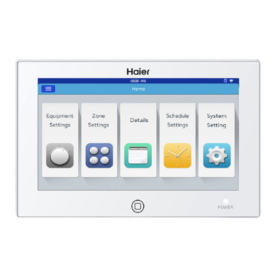
Part info for central controller ON/OFF key: After powering on, press this key to turn on controller and press for 3 seconds to turn off. Display/touch screen: Display and operation area. Screensaver key: Press to turn off screen light and press again to turn on. Power light: Power light will be on after powering on. - Page 4 Part info for central controller Fire alarm linkage contact Power: 12V DC, Communication port for there is +- for power connecting converter Power (12V, GND): 12V DC, please pay attention to +-of power. Fire alarm linkage contact (ALARM1, ALARM2): AC works normally when closed and all AC turned off when open circuit. B1, A1: Reserved Communication port (B2, A2): It is used for connecting converter, please pay attention to +-.
-
Page 5: Page & Key Explanation
Page & Key Explanation After turning on central controller, home page will show as above and detailed menu is as following: Menu/icon Function POP will show after click the icon: Online AC qty: indicating indoor unit quantity in good communication. AC detailed menu in good communication previously and then in bad communicaiton... -
Page 6: Address Setting When Using Central Controller
Address Setting When Using Central Controller When applying central controller, it is required to set address by dip switch for easy checking and maintenance. When controlling MRV For every system of AC, address starts from No. 1 to last indoor unit of the system. If totally 20 indoor units are connected in one system, address should be 1-20;... - Page 7 Address Setting When Using Central Controller The address used in central control or energy system SW03 Central address Central address=35 Central address=36 Central address=37 Central address=38 Central address=39 Central address=40 Central address=41 Central address=42 Central address=43 Central address=44 Central address=45 Central address=46 Central address=47 Central address=48...
- Page 8 Address Setting When Using Central Controller 2. Converter address setting Converter address Reserved Reserved...
- Page 9 5-20. Note: when controlling MRV, the YCZ-A004 can control max. 32 IGU05 and max. 256 indoor units. If IGU05 is more than 32 while indoor quantity is less than 256, another YCZ-A004 is needed because IGU05 exceeds 32; If IGU05 is less than 32 while indoor quantity is more than 256, another YCZ-A004 is needed because indoor quantity exceeds 256.
-
Page 10: System Structure Chart
1.System structure chart when controlling MRV: One IGU05 is needed for one AC system, and max. 32 IGU05 can be connected to one YCZ-A004. When indoor unit total quantity is less than 256, the IGU05 quantity connected to one YCZ-A004 cannot exceed 32; When IGU05 quantity is less than 32, the connected indoor quantity cannot exceed 256. -
Page 11: Function Operation
Function Operation Equipment Settings Picture 1 Press the “Equipment Settings” key on home page to enter the display interface as shown in picture 1. is the return button. This button is always presented in the column, press this button to return to the last page. means you can view air-conditioners as grouping established. - Page 12 Function Operation is the All on/All off button. If it is displaying all indoor units, then the All on/All off button is used to control all indoor units; if it is displaying the indoor units of one group, then the All on/All off button is used to control the indoor units in this group. Each grid represents an indoor unit in the air-conditioner display area, and each page can display 10 indoor units.
- Page 13 Function Operation Icon Instruction: Cooling Mode Heating Mode Central Control Dry Mode Locked Intelligent Mode Low Speed Wind Mode Automatically High Speed Medium Speed Batch change the air-conditioner mode setting: After setting one air-conditioner, press and pop window will pop out as shown in picture 6.
- Page 14 Function Operation layer, the corresponding air-conditioner icon name will also be refreshed. Zone Settings Picture 1 Press zone settings on the homepage to enter the zone setting interface, as shown in picture1. It will display setting groups and adding new group button on the left. It will only display adding new group button initially. It will display those air-conditioners which can be grouped.
- Page 15 Function Operation Click the blank text box, enter the group name (up to 6 Chinese characters) by the keyboard, and press the“ENTER” button of the keyboard after entering. Press OK key in the pop window to enter the interface as shown in picture3. Picture 3 This interface displays air-conditioner numbers, click to choose those air-conditioners need to be added to grouping.
- Page 16 Function Operation In picture5, choose one group and then click button, it will pop out the pop window and it has three lines, as shown in picture6: Picture 6 Edit group name: press the key to pop out the pop window of changing the group’s name. Edit group’s dev: press the key to pop out the list of indoor units to edit the group’s dev.
- Page 17 Function Operation Weekly Timings Choose Weekly Timingson the homepage to enter the initial schedule setting interface as shown in picture 1. Picture 1 Press to add new schedule settings. Press this button to enter the setting interface, as shown in picture 2, “On”shows when the machine starts up and “Off”...
- Page 18 Function Operation Apply Zone Settings: For setting all users: Click to select all users For setting individual user: Click the user selection textbox after all users to pop out the POP window, it will display all users, as shown in picture 4. Picture 4 Click the frame before the user’s indoor unit which you want to set, it will show a hook after selection.
- Page 19 Function Operation Select those indoor units which you want to choose by clicking the frame before them, it will show hook after selection. After setting the apply area, click blank area and pull-down lists will close. Weekly: From Monday to Sunday, it will show a hook after click, it will operate the schedule on the day you have chosen, it will circulate weekly. It will display the setting schedule as shown in picture 7, ON/OFF time will be shown below the dial plate, press the dial to enter the picture 2, you can adjust the setting time, fan speed and mode.
- Page 20 Function Operation system settings It need password to enter setting page. Click “system settings” button on the home page, you will see the picture1 below. Picture 1 Click login to enter system settings page after inputting password. System setting page includes 4 contents, as picture 2. Extra Picture 2 Mode setting: Click...
- Page 21 Function Operation Picture 4 Energy switch: You can set saving function through the button . Default is “ON”. Temperature maximum setting: You can turn up or down the maximum temperature through operating . After setting, Click , you will see a pop window what you can choose “apply to all” or “apply to one group”. Default is “apply to all”. Temperatureminimum setting: same as above.
- Page 22 Function Operation Local setting As picture 6 and picture 7. Picture 6 Picture 7 Brightness setting: You can turn up or down through the button Type selection: Choose your unit model. It will show after you pitch on the unit type. Language selection: Choose language.
-
Page 23: Installation
Installation Installation dimension Wiring diagram Wiring diagram between central controller and converter board (IGU05). heteropolarity Remark: The 485 communication cables between the twoconnecting boards and the cables between connecting board and central controller have heteropolarity. Attention please when installing. Installation dimension... -
Page 24
Installation Wiring standards All of the communication cables between each module and terminal module to the central controller are double core shielded twisted- The length of signal line Wiring dimension <100 0.3 mm ×2 100
- Page 25 Installation Rack Rack hole hole The installation of power adapter 12V- 12V+ red black Wiring between power adapter and central controller...
- Page 26 Installation After connection, put the central controller on the rack...