Table of Contents
Quick Links
READ AND SAVE THESE INSTRUCTIONS
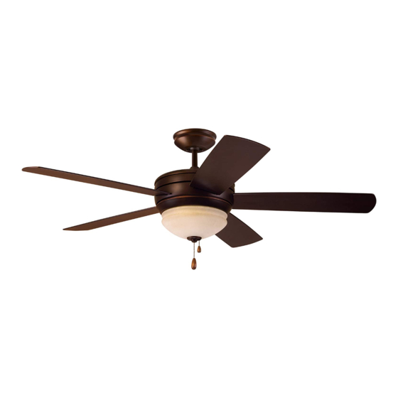
SUMMERHAVEN LED
52" Wet Location Ceiling Fan
CF850SW01 -
CF850GES01 -
CF850VNB01 -
Questions, problems, missing parts: Before returning to the store call
Part No. F40BP74430001
Revision: 190129
Owner's Manual
Model Numbers
Satin White
23.8
Net Weight:
Emerson Electric Customer Service
8 a.m. - 6 p.m., Eastern, Monday-Friday
1-800-654-3545
www.emersonfans.com
Golden Espresso
Venetian Bronze
Lbs.
TM
Form No. BP7549-1
U.L. Model No.: CF850
Table of Contents

Related Manuals for Emerson SUMMERHAVEN LED CF850SW01


Summary of Contents for Emerson SUMMERHAVEN LED CF850SW01
- Page 1 Golden Espresso CF850VNB01 - Venetian Bronze 23.8 Net Weight: Lbs. Questions, problems, missing parts: Before returning to the store call Emerson Electric Customer Service 8 a.m. - 6 p.m., Eastern, Monday-Friday 1-800-654-3545 Part No. F40BP74430001 Form No. BP7549-1 www.emersonfans.com Revision: 190129...
-
Page 2: Table Of Contents
To avoid fire, shock or injury, do not use an Emerson 2. All wiring must be in accordance with the National or any other brand of control not specifically approved Electrical Code “ANSI/NFPA 70-2017”... -
Page 3: Unpacking Instructions
Emerson Electric Co. Substitution of parts or 5.5-Watt Candelabra LED Light Bulbs accessories not designated for use with this product Hanger Bracket by Emerson Electric Co. could result in personal injury or property damage. Hanger Ball / 4.5” Downrod Assembly Fan Blade Support Plates... -
Page 4: Electrical Requirements
1. Unpacking Instructions (Continued) THIS FAN IS SUITABLE FOR WET LOCATIONS SUCH AS PORCHES, PATIOS, AND DECKS. USE ONLY WITH LIGHT KITS MARKED SUITABLE FOR USE IN WET LOCATIONS. This Manual Is Designed to Make it as Easy as Possible for You to Assemble, Install, Operate and Maintain Your Ceiling Fan Tools Needed for Assembly WARNING... -
Page 5: Ceiling Fan Assembly
3. Ceiling Fan Assembly MOTOR HOUSING Remove and discard the Two Cardboard Shipping ASSEMBLY Retainers securing the Motor Hub in the Motor Housing Assembly (Figure 1) . CARDBOARD SHIPPING Figure 1 RETAINERS (2) GREEN GROUND WIRE Remove the Hanger Ball from the 4 .5” Downrod by loosening the Set Screw in the Hanger Ball until the Ball falls freely down the Downrod (Figure 2) . - Page 6 3. Ceiling Fan Assembly (continued) 4.5" DOWNROD MOTOR LOOSEN PHILLIPS COUPLER HEAD SETSCREWS (2) Figure 4 HAIRPIN Install the Clevis Pin and secure with the Hairpin Clip CLIP (Figure 5) . CLEVIS CLEVIS The Clevis Pin must go through the Motor Coupler Holes .
- Page 7 3. Ceiling Fan Assembly (continued) While pulling up on the 4 .5” Downrod, retighten the Two Set Screws (previously loosened) in the Motor Coupler to secure the Downrod into place (Figure 6) . RETIGHTEN TWO NOTE: The set screws must be properly installed as MOTOR PHILLIPS HEAD described above, or fan wobble could result.
- Page 8 3. Ceiling Fan Assembly (continued) Route the Two 80” Motor Leads through the Hanger DOWNROD Ball . HANGER BALL PIN HANGER BALL HANGER BALL Reinstall the Hanger Ball (Figure 9) on the Downrod as GROOVE CEILING follows: COVER Position the Hanger Ball Pin through the two Holes in the Downrod and align the Ball so the Pin is captured in the Groove in the top of the Hanger Ball .
-
Page 9: How To Hang Your Ceiling Fan
4. How to Hang Your Ceiling Fan WARNING CEILING The fan must be hung with at least 7’ of clearance from floor to blades (Figure 11). WARNING The outlet box and joist must be securely mounted and capable of supporting at least 50 lbs. Use only a U.L. outlet box listed as “Acceptable for Fan Support of LEAST 22.7 kg. - Page 10 4. How to Hang Your Ceiling Fan (continued) NOTE: CEILING COVER, SUPPL Y WIRES AND FAN WIRES Carefully lift the Fan and seat the Hanger Ball/ OMITTED FOR CLARITY. Downrod Assembly into the Hanger Bracket that was just attached to the Outlet Box (Figure 13) . Be sure the Groove in the Ball is lined up with OUTLET Anti-Rotation Tab on the Hanger Bracket (Figure 13) .
-
Page 11: How To Wire Your Ceiling Fan
Emerson Electric Co. Substitution of parts or accessories not designated for use with this product by Emerson Electric Co. could result in personal injury or property damage. NOTE: If you are using an Emerson Light Fixture with your Fan, see Light Fixture Owner’s Manual for... - Page 12 5. How to Wire Your Ceiling Fan (continued) Securely connect the Fan Motor Black and Blue Wires to the Supply Black (hot) Wire using Wire Connector (supplied) (Figure 16) . SUPPLY BLACK (HOT) LISTED WIRE CONNECTOR FAN MOTOR BLACK & BLUE WIRES Figure 16 After Connections have been made, turn Wires upward...
-
Page 13: Final Assembly
6. Final Assembly Screw the Two Threaded Studs (supplied) into the Tapped Holes in the Hanger Bracket (Figure 18) . THREADED STUDS (2) Figure 18 NOTE: SUPPLY WIRES AND FAN WIRES OMITTED FOR CLARITY. Lift the Ceiling Cover up to the Threaded Studs and turn until Studs protrude through the Holes in the Ceiling Cover (Figure 19) . - Page 14 6. Final Assembly (continued) FAN BLADE Slide Blade through Center Slot in Fan Housing . Position One Blade Support Plate onto Blade . SLIDE FAN BLADE Mount Blade to Fan Housing using One Blade Support INTO CENTER SLOT Plate and secure using Three #10 - 24 x 15mm Washer Head Blade Screws (supplied) (Figure 20) .
- Page 15 6. Final Assembly (continued) Engage the Light Kit Assembly Connector to the Motor Connector (Figure 23) . The Two Connectors are Keyed and Color-Coded and must be mated correctly (color-to-color) before they can be engaged . Make sure the Connector Latch closes properly .
- Page 16 6. Final Assembly (continued) Screw Three 5 .5-Watt Candelabra LED Light Bulbs (supplied) into the Light Kit Assembly Sockets (Figure 26) . 5.5-WATT CANDELABRA LIGHT KIT LED LIGHT BULBS (3) SOCKETS (3) Figure 26 6.10 Unscrew the Finial Nut, Bowl Cap, Hex Jamnut and Rubber Washer from the Light Kit Threaded Nipple (Figure 27) .
- Page 17 6. Final Assembly (continued) 6.11 Check the operation of the Fan by gently pulling on the Pull Chain Switch (off-center pull chain) . Cut the 3-speed switch pull chain to a desired length (optional) . Connect the Small Wood Pendant (supplied) to the 3-speed switch center Pull Chain by sliding the Wood Pendant (small hole first) onto the Pull Chain (Figure 28) .
-
Page 18: Maintenance
· Downrod Extension Kits by Emerson Electric Co. Substitution of parts or accessories not designated for use with this product by Emerson Electric Co. could result in personal injury WARNING or property damage. The use of any other control not specifically approved for this fan could result in fire, shock and personal injury. -
Page 19: Troubleshooting
10. Troubleshooting WARNING FOR YOUR OWN SAFETY TURN OFF POWER AT FUSE BOX OR CIRCUIT BREAKER BEFORE TROUBLESHOOTING YOUR FAN. TROUBLE PROBABLE CAUSE SUGGESTED REMEDY 1. Fan will not start. 1 . Fuse or circuit breaker blown . 1 . Check main and branch circuit fuses or circuit breakers . -
Page 20: Repair Parts
11. Repair Parts PARTS BAG U.L. Model No.: CF850... - Page 21 11. Repair Parts Listing Part Numbers Model Number Model Number Model Number Description CF850GES01 CF850SW01 CF850VNB01 Hanger Pack Consisting of: 761655-35 761655-92 761655-89 Hanger Bracket Assembly (1) — — — Hanger Ball (1) — — — Downrod, 10” (1) — —...
- Page 22 Notes U.L. Model No.: CF850...
-
Page 23: Ceiling Fan Limited Warranty
What We Will Do To Correct Problems: If the defect is covered by this limited warranty, Emerson will repair or replace the applicable Emerson Ceiling Fan Product at no charge to You. If repair of the Emerson Ceiling Fan Product is not practical or possible within a reasonable time and no replacement Emerson Ceiling Fan Product can be provided, Emerson will refund You the actual purchase price of Your Emerson Ceiling Fan Product. - Page 24 . Air Comfort Products DIVISION OF EMERSON ELECTRIC CO. 8100 W. Florissant • St. Louis, MO 63136 Questions, problems, missing parts: Before returning to the store call Emerson Electric Customer Service 8 a.m.