Quick Links
Instruction Manual
October 2015
Type N551/N851 Packing Removal/Replacement
WaRNiNg
!
Only qualified service person should
attempt to repair these valves. The skill
required is similar to the complexity
involved in pump repair.
Before starting any type of repair, close
off the upstream valves and remove all
gas pressure from both the outlet and
inlet sides of the Type N551 emergency
shutoff valve (ESV).
Before Removing Packing
Verify that the Emergency Shutoff Valve is Type N551,
and not the previous version Type N550, by confirming
that it is marked with "1" as shown in Figure 2 below.
Please refer to D450042T012 for Type N550/N850
packing removal/replacement Instruction Manual.
If the Type N551
's operating handle closes slowly
(1)
or binds in a "no flow" condition, it could be from
binding in the packing gland area or from external
binding, such as a bent operating handle catching on
the latch block, etc. Check for some type of external
binding first.
If the binding appears to be internal, it could be from
uneven or over-tightened gland bolts (key 33). Try
loosening these two bolts 1/2 turn each and tap the
shaft (key 15) lightly side to side to align the gland
and follower bearing. Snug the bolts down evenly,
only tight enough to prevent leakage. If this does not
free the handle, the packing must be removed and be
either cleaned or replaced.
Removal of Packing
Refer to Figure 25.
If there is leakage around the shaft
(key 15), the packing should be replaced.
1. Reference to Type N551 also refers to Type N851.
Magnalube
-G is a mark owned by Trademark of Saunders Enterprises, Inc.
®
Note
www.fisherregulators.com
Type N551/N851
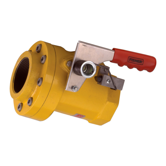
Figure 1. Type N551 in a Closed Position.
Table 1. Replacement Parts to Order
PaRT NUMBER
DESCRiPTiON
2 washers
RCN551T0012
Packing stack*
T12851T0012
Spring
T12841T0012
Follower
* Packing stack includes a black graphite female adaptor, a white Tetrafluoroethylene
(TFE) packing ring and a white TFE male adaptor.
Refer to Table 1 for all three part numbers
that must be ordered. Use Magnalube-G
grease (part number T13049T0012) 1/2 oz.
tube to apply lubricant to sealants.
caUTION
Throughout the entire removal and
replacement procedure, be sure that
the shaft (key 15) is not pulled out of
the internal lever holding the poppet
assembly. If the shaft is pulled out, the
Type N551 will have to be removed from
the line in order to properly reassemble
it. Holding the shaft in place permits the
valve to be left in-line if all line pressure
is removed.
KEY
29
30
O-ring
65
28
31

Related Manuals for Emerson Fisher N551


Summary of Contents for Emerson Fisher N551
- Page 1 Type N551/N851 Instruction Manual October 2015 Type N551/N851 Packing Removal/Replacement WaRNiNg Only qualified service person should attempt to repair these valves. The skill required is similar to the complexity involved in pump repair. Before starting any type of repair, close off the upstream valves and remove all gas pressure from both the outlet and inlet sides of the Type N551 emergency...
- Page 2 Type N551/N851 Figure 2. Type N551 marked with “1” Figure 4. Pry out gland (step 5) Figure 3. Turn gland retainer (step 3) Figure 5. Remove gland (step 6) Figure 6. Remove O-ring (step 7) 1. Remove the operating handle (key 18), fuse 6.
- Page 3 Type N551/N851 Figure 8. Remove packing carefully (step 8) Figure 7. Remove packing carefully (step 8) 9. The part shown in Figure 8 will be removed Figure 9. Replacement parts for gland from the gland: a follower bearing (key 31), a packing stack (key 30 that includes a graphite female adaptor, a TFE packing ring and a TFE male adaptor), 2 washers (key 29) and a packing...
- Page 4 Type N551/N851 Figure 13. Lubricate parts (step 4) Figure 14. Install adaptor (step 5) Figure 15. Lubricate (step 5) Figure 16. Install packing ring (step 6) Figure 17. Install graphite adaptor (step 7) Figure 18. Install follower bearing (step 8)
- Page 5 Type N551/N851 Figure 19. Follower bearing (step 8) Figure 20. Turn retainer (step 9) 4. Lubricate the shaft, gland, packing and follower 7. Install the graphite adaptor flat side out, Figure 17. bearing with a liberal amount of Magnalube ® 8.
- Page 6 Type N551/N851 Figure 21. Line up holes (step 10) Figure 22. Wind retainer, install bolts (step 11) Figure 23. Install handle (step 12) Figure 24. Align parts (step 13) 10. Remove the retainer and fit it back on the gland so 12.
- Page 7 Type N551/N851 aPPly lUBRIcaNT OR SEalaNT l1 = POlyTETRaFlUOROETHylENE (PTFE) GREaSE lUBRIcaNT S1 = THREadlOck SEalaNT 1. Lubricant and sealant must be selected such that they meet the temperature requirements. Figure 25. Type N551 Replacement Packing Assembly for 1-1/4 to 2 NPT Bodies...
-
Page 8: Parts List
For further information visit www.fisherregulators.com The Emerson logo is a trademark and service mark of Emerson Electric Co. All other marks are the property of their prospective owners. Fisher is a mark owned by Fisher Controls International LLC, a business of Emerson Process Management.