
Related Manuals for JVC MultiDyne FS-900


Summary of Contents for JVC MultiDyne FS-900
- Page 1 JVC USER MANUAL FS-900 Triple Studio Camera Interface System MultiDyne Harnessing The Power of Light 10 NEWTON PLACE HAUPPAUGE, NY 11788 USA (877) 685-8439 / (516) 671-7278 / FAX (516) 671-3362 [email protected] www.multidyne.com...
-
Page 2: Table Of Contents
FS-900 JVC Triple Studio Camera Interface System Components . . . . . . . . . . . . . . . . -
Page 3: Laser Safety Information
Camera Head Unit : Warning – Never look directly into the end of the optical fiber JVC Camera Silverback attachment procedure instructions in the next 6 steps on the following page. while either end of the system is operating. Warning – Never clean an optical fiber connector on equipment or cable that is carrying light. - Page 4 The FS-900 Triple Studio Camera Interface System consists of the two (for more information visit JVC website: http://pro.jvc.com/splash.jsp) three separate JVC ProHD GY-HM890U video cameras and their power main components: sources. In addition, each camera connects via a single fiber optic cable 1.
-
Page 5: Camera Interface Signal Paths
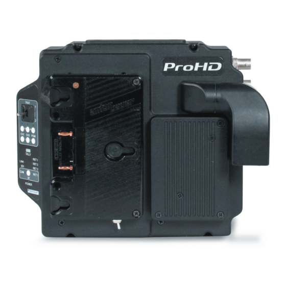
Instruction Manual, FS-900 CAMERA UNIT - CONNECTORS CAMERA INTERFACE SIGNAL PATHS Instruction Manual, FS-900 CAMERA INTERFACE SIGNAL PATHS CAMERA UNIT - CONNECTORS 3Gb/s HD-SDI 1 (camera video) 3Gb/s HD-SDI PGM return 1 (video) 3Gb/s HD-SDI return 2 (video) Prompter: SDI → HDMI (common) 2 channel Intercom 2 channel PGM audio Analog SD/HD reference (common) -
Page 6: Viewfinder Operation
Instruction Manual, FS-900 SYSTEM DESCRIPTION CAMERA UNIT - CONTROLS & INDICATORS Instruction Manual, FS-900 CAMERA UNIT - CONTROLS & INDICATORS VIEW FINDER OPERATION The Viewfinder button on the Camera Unit’s control panel is used Latching Mode can be used for longer-term, hands-free operation. To to select the video source that is output from the Viewfinder BNC talk on channel 1, quickly toggle the PTT switch upwards towards CH1 Connector. -
Page 7: Base Unit Power
SYSTEM DESCRIPTION Instruction Manual, FS-900 Instruction Manual, FS-900 BASE UNIT POWER BASE UNIT - CONTROLS & INDICATORS (Front) BASE UNIT POWER CAM 1 CAM 2 CAM 3 SDI RET 1 AUD RET 1 SDI RET 2 ICOM 1 REF IN LINK LINK LINK... -
Page 8: Application & Usage
SYSTEM DESCRIPTION Instruction Manual, FS-900 Instruction Manual, FS-900 SIGNAL FLOW - BASE UNIT APPLICATION & USAGE SIGNAL FLOW - BASE UNIT ProHD Base Unit All of the video signals coming from the camera and its accessories (viewfinder, etc.) are fed to the FS-900 Triple Studio Camera Interface system’s 1 RU base station enclosure via the SMPTE or opticalCON swivel connector which also supplies power. -
Page 9: Signal Flow: Camera Unit
SIGNAL FLOW - CAMERA UNIT Instruction Manual, FS-900 Instruction Manual, FS-900 OPERATION Base Unit - Menu Details SIGNAL FLOW - CAMERA UNIT Home Status Screen: System Status Base: Camera 1: Camera 2: Camera 3: Back Home Base Top Menu: Base System Status Fiber Status A/V Status System Status... -
Page 10: Operation: Camera Units 1, 2 & 3 - Menu Details
OPERATION Instruction Manual, FS-900 Instruction Manual, FS-900 DETAIL CONNECTOR PINOUTS - BASE UNIT Camera 1, 2 & 3 - Menu Details Detail Connector Pinouts - Base Unit Base Unit Intercom/Audio Connector Pin-out Number Description Number Description 2-Wire Intercom Pin2 / 4-Wire Intercom Ch1 Output+ 2-Wire Intercom Pin3 / 4-Wire Intercom Ch2 Output+ Home Status Screen: System Status... -
Page 11: Hirose Cable Information
DETAIL CONNECTOR PINOUTS - CAMERA UNIT Instruction Manual, FS-900 Instruction Manual, FS-900 HIROSE CABLE INFORMATION Detail Connector Pinouts - Camera Unit SMPTE Hybrid Fiber Cable system power limits Camera Unit GPIO Connector Pin-out Number Description Number Description Program (Red) Tally GPO Output Preview (Green) Tally GPO Output GPO Output Intercom MIC Ch1 PTT GPI Input... -
Page 12: Technical Specifications
Output Type Relay Contact Closure (30V, 2A max) Connector, Base Unit Connector, Camera Unit DB15 Connector, Base Unit DB25 Analog Audio EU JVC Service Contacts Type Balanced Analog Line-Level Timecode Importer (EU only) Level +4dBu nominal, +24dBu max. Type SMPTE/EBU LTC JVCKENWOOD U.K. - Page 13 10 Newton Place Hauppauge, NY 11788 (877)-685-8439 / (516)-671-7278 [email protected] www.multidyne.com...