
Related Manuals for Mitsubishi Electric AH-1006S1-E


Summary of Contents for Mitsubishi Electric AH-1006S1-E
- Page 1 July 2018 No. U237 AIR CONDUCTING FAN HANDBOOK MODELS AH-1006S1-E AH-1509S1-E AH-2009S1-E AH-3012S1-E Nameplate Warning: Repair work must be performed by the manufacturer, its service agent or a similarly qualified person in order to avoid hazards.
-
Page 2: Table Of Contents
7-1 Service flowchart ................... 8-9 7-2 Checklist ....................10 8. Before receiving repair requests ..........10 9. Service inspection list ..............10 10. Overhauling procedures ............11-15 11. Parts catalog ................ 16-24 AH-1006S1-E ..............17-18 AH-1509S1-E ..............19-20 AH-2009S1-E ..............21-22 AH-3012S1-E ..............23-24... -
Page 3: Safety Precautions
1. Safety precautions Read the following precautions thoroughly before the maintenance, and then inspect and repair the product in a safe manner. The types and levels of danger that may arise if the product is handled incorrectly are described with the warning symbols shown below. -
Page 4: Changed Points
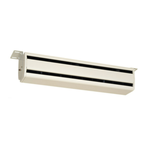
Notes: Under cover • The names in the angle brackets < > show Terminal assembly the part names in the parts catalog. (with the relay) • The illustration shows AH-1006S1-E. 4. Specifications Power supply Airflow rate Air velocity Noise Starting... -
Page 5: Outside Dimensions
5. Outside dimensions AH-1006S1-E Details of the mounting plate Air flow Terminal cover Unit (mm) AH-1509S1-E, AH-2009S1-E Details of the mounting plate 1016 Air flow Terminal cover Unit (mm) AH-3012S1-E Details of the mounting plate 1310 1266 Air flow Terminal cover... -
Page 6: Electrical Wiring Diagrams
6. Electrical wiring diagrams 6-1 Internal wiring diagrams AH-1006S1-E 80 V 80 V 80 V MOTOR MOTOR MOTOR AH-1509S1-E 80 V 80 V 80 V 120 V 120 V MOTOR MOTOR MOTOR MOTOR MOTOR AH-2009S1-E 120 V 120 V 80 V... -
Page 7: Motor Coil Diagram
The motor contains a built-in capacitor. (S coil resistance cannot be measured.) Coil resistance at a temperature of 30°C M coil Thermal fuse Capacitor 114°C S coil Resistance (Ω) Motor rated Capacitor ca- Model Motor code voltage (V) pacitance (μF) M coil S coil AH-1006S1-E AH-1509S1-E AH-2009S1-E AH-3012S1-E ─ 7 ─... -
Page 8: Troubleshooting
7. Troubleshooting Work precautions • When servicing, recreate the malfunction two or three times before starting repairs. • When servicing, always keep proper footing. • When servicing, always unplug the power cord from the outlet, or turn off the circuit breaker. Pay sufficient attention to avoid electric shock or injury. - Page 9 Abnormal noise Is the rated power supplied to the product? Supply the rated power to the product. Is the product securely mounted? Mount the product securely. Is the strength at the mounting point of the product Make sure of the strength at the mounting enough? point.
-
Page 10: Checklist
7-2 Checklist Error Cause Action 1 The product Is the circuit breaker turned on? Turn on the breaker. does not oper- Is the external ON/OFF switch turned Turn on the external ON/OFF switch. ate. Is the wiring correct? Check the wiring. Is there any connection failure of the Check that the wiring connections are securely wiring? -
Page 11: Overhauling Procedures
10. Overhauling procedures Work precautions • Before replacing parts or components, follow the instructions described in the troubleshooting. • When servicing, always keep proper footing. • When servicing, always unplug the power cord from the outlet, or turn off the circuit breaker. Pay sufficient attention to avoid electric shock or injury. - Page 12 When the coil resistance at ordinary temperatures is equivalent to the values below, the motor is normal. Resistance (Ω) Motor rated Capacitor ca- Model Motor code voltage (V) pacitance (μF) M coil AH-1006S1-E AH-1509S1-E AH-2009S1-E AH-3012S1-E Measure the resistance of all the motors that are not working to identify the faulty motors. ─ 12 ─...
- Page 13 [3] Remove the guard. Guard a. Turn the main unit upside down. b. Remove the screws (PTT screws 4x20) and special washers (4.2) (indicated by Model Screws (pieces) AH-1006S1-E AH-1509S1-E AH-2009S1-E Guard Hook AH-3012S1-E Tightening torque: 1.39 to 1.89 N . m c.
-
Page 14: Ah-1006S1-E
[2] Unscrew the screws (PTT screws 4x6, indicated by ), and remove the resistor assembly. Screws and ce- Resistance Model ment resistors (Ω) (pieces) AH-1006S1-E AH-1509S1-E AH-2009S1-E AH-3012S1-E Resistor assembly Tightening torque: 1.39 to 1.89 N . m [3] Disconnect the three-pin connector. - Page 15 (4) Remove the terminal assembly (with the relay). [1] Disconnect the power wires. See (1) [3]. [2] Remove the under cover. See (2) [1]. [3] Disconnect the three-pin connector. See (3) [3]. [4] Cut the crimp cap (indicated by ) to disconnect the motor connection. See (3) [4] for cutting of the crimp cap.