
Related Manuals for GE Bently Nevada 330400


Summary of Contents for GE Bently Nevada 330400
- Page 1 (217) 352-9330 | Click HERE Find the GE / Bently Nevada 330400-02-00 at our website:...
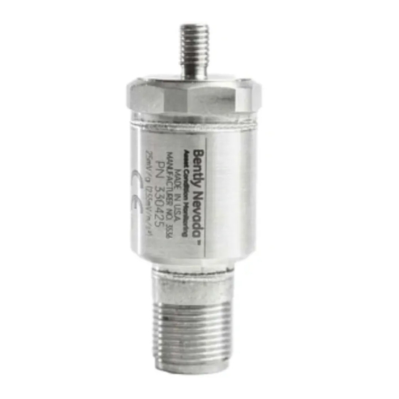
- Page 2 Operation Manual Bently NevadaTM Asset Condition Monitoring B E N T L Y N E V A D A MADE IN U.S.A. PN 3304XX xxx mv/c (xxx mV/m/s2) 330400 and 330425 Accelerometer imagination at Part Number 127088-01 Rev. H(08/07)
- Page 3 Contact information The following ways of contacting Bently Nevada are provided for those times when you cannot contact your local representative: Mailing Address 1631 Bently Parkway South Minden, Nevada USA 89423 Telephone 1.775.782.3611 1.800.227.5514 Fax 1 . 7 7 5 . 2 1 5 . 2 8 7 3 Internet w w w .
- Page 4 330400 and 330425 Accelerometer Operation Manual Additional Information Notice: This manual does not contain all the information required to operate and me lintain the product. Refer to the following manuals for other required information. 3300/25 Dual Accelerometer Input Monitor (Peak) Maintenance Manual (Part Number 80181-01) 3300/26 Dual Accelerometer Input Monitor (RMS) Maintenance Manual (Part Number 86800-01)
- Page 5 Contents 1. O p e r a t i n g Information1 1.1 A p p l i c a t i o n 1 1.2 P r i n c i p l e of Operation1 1.3 C o m p a t i b l e Monitoring Systems2 2.
- Page 6 330400 and 330425 Accelerometer Operation Manual Accessories and Spare Parts 330400 Accelerometer Options 6.1.1 330400 Accelerometer 6.1.2 Mounting Stud: Option A 6.1.3 Agency Approvals: Option B 330425 Accelerometer Options 6.2.1 330425 Accelerometer 6.2.2 Mounting Stud C Option A 6.2.3 Agency Approvals C Option B Transducer Housing Interconnect Cable Options...
- Page 7 Section 1- Operating Information 1. Operating Information This section contains information that will help you prepare for the installation of the Accelerometer Systems. General information for typical applications, principles of operation, and monitoring compatibility of the Accelerometers are presented in this section. 1.1 Application Accelerometers are very effective when used for the measurement of high frequency vibrations.
- Page 8 330400 and 330425 Accelerometer Operation Manual The internal circuitry of the 330400 and 330425 accelerometers automatically sets the output dc bias when power is supplied. The dc bias and ac signal appears across pin "A" and "C". ACCELEROMETER SIGNAL A® SHIELDED SHLD CABLE...
- Page 9 Section 1 - O p e r a t i n g I n f o r m a t i o n Table 1-2. Compatible Full-Scale Range Options for the 330400 Accel Monitoring System Compatible Full-scale with No Integration F u l l -Scale with Integration r m s 3300/25 C o m p a t i b l e with all full-scale range options C o m p a t i b l e with all full-scale range options...
- Page 10 330400 and 330425 Accelerometer Operation Manual 2. Installation 2.1 Receiving Inspection Inspect the components of the order when they are received to see if there was any damage during shipping. Keep all shipping forms and invoices. If any shipping damage is apparent, file a claim with the carrier and submit a copy to Bently Nevada.
- Page 11 Section 2 - Installation with Dow Corning 340 or equivalent grease and then screw the adapter into the mounting surface. The grease is required to ensure good coupling between the adapter and the mounting surface at high frequencies. A light oil may also be used.
- Page 12 330400 and 330425 Accelerometer Operation Manual 2.2.6 Sealing the Interconnect Cable C A U T I O N When the conduit is routed through hazardous areas, the ends of the conduit must be sealed to prevent hazardous gases from escaping into non-hazardous areas.
- Page 13 Section 2 - Installation 2.3.3 3500 MONITORING SYSTEM Connect the cable "A" lead to "SIG/A" terminal on the monitor, the "B" lead to "PWR/B", and the "C" lead to "COM". The terminal connections for the 3500/42 Monitoring System appear in Figure 2-3 and Figure 2-4. Refer to the 3500/42 Operation and Maintenance Manual (part number 129773-01) and 3500 Field Wiring Diagram Package (part number 130432-01) for further information.
- Page 14 330400 and 330425 Accelerometer Operation Manual MONITOR O OK moN EOM A C C E L E R O M E T E R P I N O U T (-OUR ®®S(S)N®SSNOCS)®® CHAN1‘.._ A.10, TOR BLACK WHITE PWR/B SIG/A SHIELD ( G R E E N ) PWR/B TO S I N G L E E A R T H P O I N T SIG/A...
- Page 15 Section 2 - Installation ACCELEROMETER PIN OUT PROX/SEISkre — HLACK I/O MODULE WHITE PVIA SNLO PNR/6 A m l 93/8 SHED F e - 1 P V , / 1 3 C O M 0 9C/A 0 SKI) PVIRTM Co1 Eli 2./8 S H t 0 D 1 3 3 8 M...
- Page 16 330400 and 330425 Accelerometer Operation Manual ACCELEROMETER PIN O U T C D ®CD C D CD C D MACHINE C[D CD 3500/42 PROX/SEISMIC I/O MODULE lova W I T H EXTERNAL TERMINATIONS WI T HOUT BARRIERS GREEN WHITE BLACK EXTERNAL TERMINA TION BLOCK '28015-02 SHOWN L Figure 2-4 Accelerometer/3500 System Connections Using 16925...
- Page 17 Section 2 - Installation ACCELEROMETER PIN OUT OSC:LLOSCOPE BLACK SHIELD (GREEN) WHITE POWER SUPPLY 24 V d c Figure 2-5 Accelerometer/External Power Supply Connections Using 16925 Interconnect Cable...
- Page 18 330400 and 330425 Accelerometer Operation Manual 3. Maintenance This section shows how to check the performance of the 330400 and 330425 Accelerometers. Table 3-1 lists the recommended maintenance equipment. If the equipment is not available, contact the nearest Bently Nevada field office, or return the transducer to the factory or a testing laboratory for testing.
- Page 19 Section 3 - Maintenance Display Goes Positive First .-- Time Figure 3-1 Polarity Check Oscilloscope Display...
- Page 20 330400 and 330425 Accelerometer Operation Manual 4. Field Testing and Troubleshooting Use the following procedures to test an installed 330400 and 330425 Accelerometer and isolate a suspected malfunction. The 330400 and 330425 Accelerometers are hermetically-sealed units with no adjustments or field repairable components.
- Page 21 Section 4 - Field Testing and Troubleshooting Interconnect Cable is Damaged: Shorted Visually inspect the interconnect cable for apparent damage. Disconnect the interconnect cable at both ends and measure the resistance among the three conductors of the interconnect cable. If intermittent or shorted, replace the cable. Interconnect Cable is Damaged: Open Disconnect the interconnect cable at both ends.
- Page 22 330400 and 330425 Accelerometer Operation Manual 5. Specifications 5.1 330400 Accelerometer Parameters are specified at 25°C (77°F) unless otherwise specified. Note: Operation outside the specified limits will result in false readings or loss of machine monitoring. 5.1.1 Electrical Scale factor 10.2 mV/( m/s2) (100 mV/g) ±...
- Page 23 Section 5 - Specifications 5.2 330425 Accelerometer Parameters are specified at 25°C (77°F) unless otherwise specified. Note: Operation outside the specified limits will result in false readings or loss of machine monitoring. 5.2.1 Electrical Scale factor 2.55 mV/(m/s2) (25 mV/g) ±5% @ 100Hz Frequency Response ±...
- Page 24 330400 and 330425 Accelerometer Operation Manual 5.2.2 Environmental for the 330400 and the 330425 Accelerometer Operating Temperature Range -55° to 121°C (-67° to 250°F) Shock Limit 49030 m/s2 pk (5000 g pk) maximum Humidity Limit 100% condensing, non-submerged. Case is hermetically-sealed 5.2.3 Mechanical for the 330400 and 330425 Accelerometer Dimensions...
- Page 25 Section 5 - Specifications Bend Radius (Unarmored) 25.4 mm (1.00 in) Operating Temperature Range -55° to 200°C (-67° to 392°F) Maximum 0.D 4.06 mm (0.0160 in) 5.2.5 Standard Armored Interconnect Cable: Armored Materials Hose Material AISI 302 or 304 Stainless Steel Joint Material Silver Solder or Welded Hose Diameter...
- Page 26 330400 and 330425 Accelerometer Operation Manual Bend Radius Unarmored 25.4 mm (1.00 in) Operating Temperature Range -55° to 200°C (-67° to 392°F) Boot Material Fluorosilicone Elastomer Operating Temperature -57° to 177°C (-70° to 350°F) Maximum I.D 21.34 mm (0.840 in) Maximum 0.D 28.19 mm (1.11 in) Maximum Length...
- Page 27 Section 5 - Specifications 5.3 Mechanical Outline 3 PIN, MIL—C-5015 RECEPTACLL /— 0,625-24 ONES 52.1 (2,0) B E N T LY •,) N E VA D A MADE I S U S A _ PN 3304XX 61.0 (2.4) X X X mv/G (xx.x my/m/s, VOUNTING STUD (1/4-28 or V8X1-6g OPTION)
- Page 28 330400 and 330425 Accelerometer Operation Manual Scale Factor mV/(m/s^2) Scale Factor (mV/g) 100000 1000 10000 Frequency (Hz) 5.4 330400 Accelerometer Frequency Response Figure 5-2 Typical 330400 Accelerometer Frequency Response (English Units) 1 0 0 0 0 1 0 0 0 0 0 Frequency (Hz) Figure 5-3 Typical 330400 Accelerometer Frequency Response (Metric Units)
- Page 29 Section 5 - Specifications Scale Factor (mV/g) 10000 100000 1000 Frequency (Hz) 5.5 330425 Accelerometer Frequency Response Figure 5-4 Typical 330425 Accelerometer FrequencyResponse(English Units) <„, to 2.4 as 0 1 0 0 0 0 1 0 0 0 0 0 Frequency (Hz) Figure 5-5 Typical 330425 Accelerometer Frequency Response (Metric Units)
- Page 30 330400 and 330425 Accelerometer Operation Manual 6. Accessories and Spare Parts 6.1 330400 Accelerometer Options When ordering the 330400 Accelerometer, you may choose from the following list of options: 6.1.1 330400 Accelerometer 330400-AXX-BXX A: Mounting Stud 0 1 1 / 4 - 28 Integral Stud 0 2 M 8 X 1 - 6 g integral Stud B: Agency Approval Option 0 0 N o t required...
- Page 31 Section 6 - Accessories and Spare Parts 6.2.3 Agency Approvals C Option B The 330425 Accelerometer is agency approved. Consult with your local Bently Nevada sales representative for information regarding approvals. 6.3 Transducer Housing The 330400 and 330425 Accelerometers are compatible with the 43217-02 Accelerometer Housing.
- Page 32 330400 and 330425 Accelerometer Operation Manual PART NUMBER 16925 — (SEE NOTE) 22 AWG CABLE " " C O N N E C T O R PART NUMBER 0.160 DIA (4.1 m m ) "A" WHT .,.. I : 0 "B" RED 'C"...
- Page 33 Section 6 - Accessories and Spare Parts PART NUMBER 1 3 0 5 3 9 - ( S E E NOTE) PLASTIC CLAMP BOOT CONNECTOR CUSTOMER I.D BNC PN " " 0.196 ( 5 m m ) "El" RED "C" BLK 4.00 --=.1 2 .