
Related Manuals for GE DMS Go


Summary of Contents for GE DMS Go
- Page 1 Measurement & Control Solutions Ultrasonic DMS Go Operator’s Manual P/N 1347494 Rev. 1 October 2010 Your Complete Source for www.BergEng.com 1-847-577-3980 Testing Equipment. Since 1969! Berg Engineering & Sales Company, Inc. [email protected]...
- Page 2 Your Complete Source for www.BergEng.com 1-847-577-3980 Testing Equipment. Since 1969! Berg Engineering & Sales Company, Inc. [email protected]...
- Page 3 DMS Go Ultrasonic Thickness Gauge Operator’s Manual P/N 1347494 Rev. 1 October 2010 GESensingInspection.com ©2010 General Electric Company. All rights reserved. Technical content subject to change without notice. Your Complete Source for www.BergEng.com 1-847-577-3980 Testing Equipment. Since 1969! Berg Engineering & Sales Company, Inc.
- Page 4 [no content intended for this page - proceed to next page] Your Complete Source for www.BergEng.com 1-847-577-3980 Testing Equipment. Since 1969! Berg Engineering & Sales Company, Inc. [email protected]...
-
Page 5: Table Of Contents
1.8 DMS Go Software Options..................19 DMS Go Operator’s Manual Your Complete Source for www.BergEng.com... - Page 6 2.6 Using the Calibration Reminder Alarm (PROBE & CAL - CAL REMINDER) ......... . . 70 DMS Go Operator’s Manual Your Complete Source for www.BergEng.com...
- Page 7 4.1.1 Setting up a Dual Element Transducer (MEASURE - DUAL MULTI) ..........89 DMS Go Operator’s Manual Your Complete Source for www.BergEng.com...
- Page 8 6.2 Viewing the Data Recorder File in a List or Spread Format (DR - VIEW) ..........109 DMS Go Operator’s Manual Your Complete Source for www.BergEng.com...
- Page 9 A.1.3 Pixel Resolution ..................125 DMS Go Operator’s Manual Your Complete Source for www.BergEng.com...
- Page 10 A.4 I/O Connectors ................... . 128 viii DMS Go Operator’s Manual Your Complete Source for www.BergEng.com...
- Page 11 A.18File Formats ....................132 DMS Go Operator’s Manual Your Complete Source for www.BergEng.com...
- Page 12 B.6.1 Example of Custom Point File ................148 DMS Go Operator’s Manual Your Complete Source for www.BergEng.com...
- Page 13 C.2.2 The Risks and Your Role in Reducing Them ............. . . 152 Appendix D. EN15317 Specifications Appendix E. Probes DMS Go Operator’s Manual Your Complete Source for www.BergEng.com 1-847-577-3980 Testing Equipment.
- Page 14 Contents DMS Go Operator’s Manual Your Complete Source for www.BergEng.com 1-847-577-3980 Testing Equipment. Since 1969! Berg Engineering & Sales Company, Inc. [email protected]...
- Page 15 For battery operation of this instrument, GE only recommends the use of a lithium-ion battery. You should only use the battery recommended by GE for operation of this instrument. You can charge the lithium-ion battery either within the instrument itself or with the external battery charger.
- Page 16 • Operator training • Knowledge of special technical test requirements and limits • Choice of appropriate test equipment DMS Go Operator’s Manual Your Complete Source for www.BergEng.com 1-847-577-3980 Testing Equipment. Since 1969! Berg Engineering & Sales Company, Inc. [email protected]...
- Page 17 Test objects made of other materials (e.g., nonferrous metals or plastics) may have larger sound velocity variations, which could adversely affect the accuracy of the measurements. DMS Go Operator’s Manual Your Complete Source for www.BergEng.com...
- Page 18 Such measurement errors can be avoided either by ensuring that the reference block and the test object are at the same temperature, or by using a correction factor obtained from published tables. DMS Go Operator’s Manual Your Complete Source for www.BergEng.com...
- Page 19 ANY KIND WITH RESPECT TO OUR PRODUCTS, WHETHER EXPRESS OR IMPLIED, INCLUDING ANY IMPLIED WARRANTIES OF MERCHANTABILITY, FITNESS FOR A PARTICULAR PURPOSE, NON-INFRINGEMENT, TITLE AND ANY WARRANTIES ARISING FROM COURSE OF PERFORMANCE, COURSE OF DEALING OR TRADE USAGE. DMS Go Operator’s Manual xvii Your Complete Source for www.BergEng.com...
- Page 20 Preface [no content intended for this page - proceed to next page] xviii DMS Go Operator’s Manual Your Complete Source for www.BergEng.com 1-847-577-3980 Testing Equipment. Since 1969! Berg Engineering & Sales Company, Inc. [email protected]...
-
Page 21: Chapter 1. General Information
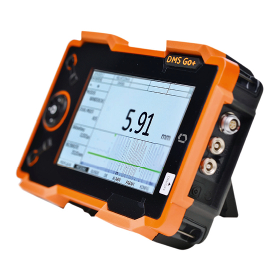
Chapter 1. General Information The DMS Go is a portable ultrasonic thickness gauge. In addition to its light-weight design, the DMS Go includes a clean and simple user interface and a large, easy-to-read color WVGA (800x480) display. The instrument provides ultrasonic flaw detection and thickness measurements., and can store scans, operating parameters, and reports. -
Page 22: Supplying Power To The Instrument
Connection Pulse/Transmit Probe Connection Battery Charger Connection 1/4-Turn Screw (CW to close, CCW to open) Figure 1: Rear and Side Views of the DMS Go Case DMS Go Operator’s Manual Your Complete Source for www.BergEng.com 1-847-577-3980 Testing Equipment. Since 1969! Berg Engineering &... - Page 23 Chapter 1. General Information 1.1 Supplying Power to the Instrument (cont.) The DMS Go can be powered in either of two ways (see Figure 1 on page 2): • A lithium-ion battery pack that is installed in a compartment on the rear of the case, or •...
-
Page 24: Powering The Instrument On And Off
1.3 Using the Keypad The DMS Go is designed to provide the user quick access to all of the instrument's functions. Its easy-to-use menu system allows any function to be accessed with a minimum of effort. - Page 25 Main Menu Row, Function 3, 4 Toggle Consisting of 7 Menus Function Line Display Screen Figure 2: Front Panel of the DMS Go DMS Go Operator’s Manual Your Complete Source for www.BergEng.com 1-847-577-3980 Testing Equipment. Since 1969! Berg Engineering & Sales Company, Inc.
-
Page 26: Instrument Orientation
1.3.1 Instrument Orientation One of the innovative features of the DMS Go is the user option to quickly and easily rotate the instrument 180° to accommodate either right-hand or left-hand operation. During this process, the display image is also rotated to allow proper viewing. Figure 3 below shows the instrument in both orientations. -
Page 27: Keypad Components
Chapter 1. General Information 1.3.2 Keypad Components The DMS Go keypad includes the following items (see Figure 2 on page 5): • Center-press joystick ( ): The joystick may be moved either “left or right” or “up or down.” In addition, the center of the joystick may either be “pressed”... - Page 28 (OBSTR, NOTE, uGRID) F3: CLEAR (B-Scan and Min/Max), NEXT, CRSE+ (numeric fields), uGRID (in DR grid) • Note: You can also assign one of five custom functions to F4. DMS Go Operator’s Manual Your Complete Source for www.BergEng.com 1-847-577-3980 Testing Equipment.
-
Page 29: Joystick Functions
(In the DR Properties option, you can also navigate in the submenu.) When you push the joystick slightly, numerical values change in small increments. Pushing the joystick to the extreme right or left will cause values to change rapidly or in larger increments. DMS Go Operator’s Manual Your Complete Source for www.BergEng.com 1-847-577-3980 Testing Equipment. -
Page 30: Multi-Key Functions
Pressing and holding these three buttons simultaneously causes the instrument to initiate a software update. Note: A formatted SD card with a valid DMS Go update file in the root directory must be inserted prior to pressing these buttons. Be aware that the root directory can have only one file with an .sdu extension. - Page 31 Pressing and holding these two buttons simultaneously causes the instrument to capture the current screen as a jpg file for future study. The DMS Go stores the jpg file in either the root directory or in the currently active DMS Go folder of the SD card.
-
Page 32: Using The Display
Chapter 1. General Information 1.4 Using the Display A typical display for the DMS Go is illustrated in Figure 4 below. See the following pages for step-by-step instructions on accessing these menus. Function 2 Readings Battery Indicator Function 1 Function 4... -
Page 33: Display Icons
Single-echo —Indicates that the DMS Go is in single-echo measurement mode (see page 58) Dual-echo — Indicates that the DMS Go is in dual-echo measurement mode (see page 58). Dual-Multi — Indicates that the DMS Go is measuring in Dual-Multi mode (see page 68). -
Page 34: Using The Sd Slot, Usb Connector & I/O Connector
1.6 Using the SD Slot, USB Connector & I/O Connector The DMS Go uses a standard 2 to 8 GB SD memory card for storing data set files and reports and for loading an instrument software upgrade (see “Multi-Key Functions” on page 10). The SD card slot is located in a compartment on the top of the instrument, along with a USB connector and an I/O connector (see Figure 5 below). -
Page 35: Removing The Sd Card
The edge of the card with the row of gold-colored electrical contacts must enter the slot first. Slide the card fully into the slot and push gently until the card seats into its socket. Then, close the SD card slot cover. DMS Go Operator’s Manual Your Complete Source for www.BergEng.com 1-847-577-3980 Testing Equipment. -
Page 36: Connecting The Usb Port
The connector closest to the hinge of the top compartment cover (see Figure 5 on page 14) is a Mini USB port. If you use a standard USB cable to connect the DMS Go to a PC (no special drivers are required), the installed SD card will be added to the list of active drives on the PC. -
Page 37: Connecting The I/O Port
Sync & Alarm pins - these signals are accessible to the user via a special optional cable. To use this connector you must order the optional DMS Go cable, which is available as P/N 022-510-032. The pin designations for connecting the open end of this cable are listed in Table 2 below:... -
Page 38: Typical Dms Go Operation
Scroll down to CALIBRATION. Move the joystick right to begin the calibration process. Follow the on screen prompts to complete the calibration process. (The calibration process might ask you to put the probe on the zero block, the round block on the DMS Go stand.) -
Page 39: Dms Go Software Options
If you purchase a specific software option, GE will provide a specific activation code. These specific options include TOPCOAT and AUTO-V, Extended Data Recorder, and USM Go Mode. Activation codes matched to your DMS Go serial number can be input via the CODE submenu (see “Entering a New Activation Code for Options (CONFIG - CODE)”... - Page 40 Chapter 1. General Information [no content intended for this page - proceed to next page] DMS Go Operator’s Manual Your Complete Source for www.BergEng.com 1-847-577-3980 Testing Equipment. Since 1969! Berg Engineering & Sales Company, Inc. [email protected]...
-
Page 41: Chapter 2. Instrument Setup
2.1 Display Screen and Keypad Features The DMS Go user interface has been designed for clarity and ease of use. Figure 6 on page 20 shows the major components of the display and the keypad. To access the menus and parameters, click the joystick button to move from submenu to submenu, and then to access the parameters within a submenu. - Page 42 Reading 2 Battery Level Function 1 Function 4 Function 3 Large Reading Menu Bar Figure 6: Display Screen Features DMS Go Operator’s Manual Your Complete Source for www.BergEng.com 1-847-577-3980 Testing Equipment. Since 1969! Berg Engineering & Sales Company, Inc. [email protected]...
- Page 43 Chapter 2. Instrument Setup HOME SEND CRSE+ CRSE- Figure 7: Function Keys and Associated Windows DMS Go Operator’s Manual Your Complete Source for www.BergEng.com 1-847-577-3980 Testing Equipment. Since 1969! Berg Engineering & Sales Company, Inc. [email protected]...
-
Page 44: The Menu System
Chapter 2. Instrument Setup 2.2 The Menu System The DMS Go menu system allows the operator to select and adjust various instrument features and settings. It includes: • Probe & Cal Menu: Consists of several functions used to configure the probe type, zeroing and thickness calibration. They are Probe (page 54), TG Mode (page 58), Thickness Calibration (page 60), Zero (page 63), Calibration (page 61), Probe Zero (page 65), Velocity (page 68), Calibration Reminder (page 70), and Temperature Compensation (page 68). - Page 45 (page 37), Velocity Reference Block (page 38), Lockout (page 46), Menu Mode (page 48), Function Key (page 49), Password (page 50), Code (page 52), and About (page 45). The information provided in this chapter describes how to set up a DMS Go for operation and for individual measurements. DMS Go Operator’s Manual Your Complete Source for www.BergEng.com...
-
Page 46: Initial Setup
2.3 Initial Setup In this section, you’ll learn how to configure the DMS Go display and operating features. Follow these procedures to turn the instrument ON and make initial adjustments to the control settings. Because the instrument can be set to save the control settings when it is turned OFF and restore them when it is turned back ON, you won’t have to repeat these adjustments unless a change is required. -
Page 47: Language, Units Of Measurement, Date, And Time
Use the procedures in this section to adjust the units of measurement, the date, the time, and the language that appears on the display screen, as well as the operator level and the password. These parameters are in the CONFIG submenu, highlighted in Figure 8 below. Figure 8: The CONFIG Submenu DMS Go Operator’s Manual Your Complete Source for www.BergEng.com 1-847-577-3980 Testing Equipment. - Page 48 Use the joystick ( ) to move to another function, or press HOME to return to the Main Menu. The display screen and report language are now set to the choice last selected. DMS Go Operator’s Manual Your Complete Source for www.BergEng.com 1-847-577-3980 Testing Equipment.
- Page 49 To change the units of measurement, move the joystick left or right ( ) to move to another function, or press HOME to return to the Main Menu. After making your choice, use the joystick ( DMS Go Operator’s Manual Your Complete Source for www.BergEng.com 1-847-577-3980 Testing Equipment.
- Page 50 ) to move to another function, or press HOME to return to the Main Menu. The date and time format shown on the display screen and in the out reports are now set to the choice last selected. DMS Go Operator’s Manual Your Complete Source for www.BergEng.com...
- Page 51 ) to move to another function, or press HOME to return to the Main Menu. The After making your choice, use the joystick ( date and time shown on the display screen and in the reports are now set to the choice last selected. DMS Go Operator’s Manual Your Complete Source for www.BergEng.com 1-847-577-3980 Testing Equipment.
- Page 52 Use the joystick ( control. After making your choice, use the joystick ( ) to move to another function, or press HOME to return to the Main Menu. DMS Go Operator’s Manual Your Complete Source for www.BergEng.com 1-847-577-3980 Testing Equipment. Since 1969! Berg Engineering &...
- Page 53 Setting the Time Before an Unattended Meter Powers Down (CONFIG - POWER DOWN) The Power Down function powers down the instrument after a preset amount of time in which no one enters any inputs into the DMS Go; the unit is receiving no button or joystick inputs from the user, and it is not receiving a valid thickness indication (as indicated by a display solid lettering, rather than hollow).
-
Page 54: Screen Appearance
To change the display color scheme, move the joystick to scroll to the desired scheme. (Figure 9 on the next page shows the possible color schemes.) ) to move to another function, or press HOME to return to the Main Menu After making your choice, use the joystick ( DMS Go Operator’s Manual Your Complete Source for www.BergEng.com 1-847-577-3980 Testing Equipment. - Page 55 Chapter 2. Instrument Setup 2.3.2a Setting the Display Color (CONFIG-COLOR) (cont.) Figure 9: Available DMS Go Color Schemes DMS Go Operator’s Manual Your Complete Source for www.BergEng.com 1-847-577-3980 Testing Equipment. Since 1969! Berg Engineering & Sales Company, Inc. [email protected]...
- Page 56 Use the joystick ( To change the brightness level, move the joystick ( Note: GE recommends a setting of 6 to maximize battery time. ) to move to another function, or press HOME to return to the Main Menu After making your choice, use the joystick ( DMS Go Operator’s Manual...
- Page 57 To change the reading setting, move the joystick ( ) to move to another function, or press HOME to return to the Main Menu. After making your choice, use the joystick ( DMS Go Operator’s Manual Your Complete Source for www.BergEng.com 1-847-577-3980 Testing Equipment.
- Page 58 To change the resolution level, move the joystick ( After making your choice, use the joystick ( ) to move to another function, or press HOME to return to the Main Menu. DMS Go Operator’s Manual Your Complete Source for www.BergEng.com 1-847-577-3980 Testing Equipment.
- Page 59 Setting the Zero Block Configuration (CONFIG-ZERO BLOCK) If you are using a zero block for your probe, you can enter its thickness and velocity configuration into the DMS Go. (See “Setting the Probe Zero (PROBE & CAL - ZERO)” on page 63.)
- Page 60 (@ 4700 m/s). If you are using a velocity reference block for your probe, you can enter both the velocity and coating velocity into the DMS Go. However, this function is only necessary when the TopCOAT/Auto-V option is enabled.
- Page 61 Press F2 (DONE) to confirm the entry, or F1 (EXIT) to close the window without changing the configuration. After making your choice, use the joystick ( ) to move to another function, or press HOME to return to the Main Menu. DMS Go Operator’s Manual Your Complete Source for www.BergEng.com 1-847-577-3980 Testing Equipment.
- Page 62 After making your choice, use the joystick ( ) to move to another function, or press HOME to return to the Main Menu. Note: In the B-Scan and Min/Max modes, the update rate is always 32 Hz. DMS Go Operator’s Manual Your Complete Source for www.BergEng.com 1-847-577-3980 Testing Equipment.
- Page 63 Most GEIT thickness gauge probes are designed to be used in negative rectification. Figure 14: Typical RF and Rectified Signals DMS Go Operator’s Manual Your Complete Source for www.BergEng.com 1-847-577-3980 Testing Equipment.
- Page 64 RF means no rectification. The rectification determines the cycle in which the zero crossing measurement is made. Under ordinary circumstances, GE recommends not changing this parameter. It is only necessary to change the rectification mode for special probes or special applications.If necessary, use the procedure on the next page to select a rectification mode.
- Page 65 ) to select the desired rectification method. ) to move to another function, or press HOME to return to the Main Menu. After completing your selection, use the joystick ( DMS Go Operator’s Manual Your Complete Source for www.BergEng.com 1-847-577-3980 Testing Equipment.
- Page 66 To change the radix, move the joystick. ) to move to another function, or press HOME to return to the Main Menu. After making your choice, use the joystick ( DMS Go Operator’s Manual Your Complete Source for www.BergEng.com 1-847-577-3980 Testing Equipment.
- Page 67 2.3.2j Obtaining Information on the Program (CONFIG-ABOUT) Data on the DMS Go serial number and codes may be needed for your service provider to assist with any updates or corrections. It is available through the ABOUT function. In the MAIN menu, scroll to the CONFIG submenu using the joystick (...
-
Page 68: Setting Security Functions
Permitting a User to Access Specified Functions (CONFIG - LOCKOUT) A supervisor might need other users to have access only to particular DMS Go functions. The DMS Go has two user levels: Expert and Inspector. The Expert can access all functions, while the Inspector can use only those functions that have not been locked out in the LOCKOUT menu. - Page 69 Use the joystick to toggle to any functions that need to be accessed, and press the center of the joystick ( ) to enable the function. ) to move to another function, or press HOME to return to the Main Menu. After making your choice, use the joystick ( DMS Go Operator’s Manual Your Complete Source for www.BergEng.com 1-847-577-3980 Testing Equipment.
- Page 70 Setting the User Level (CONFIG - MENU MODE) The DMS Go has two user levels: Expert and Inspector. The Expert can access all functions, while the Inspector can use only those functions that have not been locked out in the LOCKOUT menu. To set the menu to the appropriate level, complete the following steps: In the MAIN menu, scroll to the CONFIG submenu using the joystick ( ) to select the MENU MODE.
- Page 71 ) to select the function titled FUNC KEYS. Select the function to be associated with F4. Use the joystick ( After making your choice, use the joystick ( ) to move to another function, or press HOME to return to the Main Menu. DMS Go Operator’s Manual Your Complete Source for www.BergEng.com 1-847-577-3980 Testing Equipment.
- Page 72 2.3.3d Entering a New Password (CONFIG - PASSWORD) To enter a new password for the DMS Go, complete the following steps: In the MAIN menu, scroll to the CONFIG submenu using the joystick ( ) to select the PASSWORD function, and toggle it ( Use the joystick ( ) to open the password window (Figure 17 below).
- Page 73 Note: In case you had a previous PASSWORD (OLD) system first asks you for the OLD PASSWORD before it allows you to enter the NEW PASSWORD. The DMS Go also allows you to have NO PASSWORD. In this case there is no access.
- Page 74 If you purchase a specific software option, GE will provide a specific activation code. These specific options include TOPCOAT and AUTO-V, Extended Data Recorder, and USM Go Mode. Activation codes matched to your DMS Go serial number can be input via the CODE submenu, which is located in the CONFIG menu.
- Page 75 GEIT. After completing the code entry, confirm the entry by pressing F2 (CONFIRM). If the code is not valid, the DMS Go displays the message “Error - Invalid Code!”...
-
Page 76: Installing A Probe
Chapter 2. Instrument Setup 2.4 Installing a Probe Follow the instructions in this section to install a probe on your DMS Go. Receive 2.4.1 Connecting the Probe Probe When connecting a probe to the instrument, the following steps must be taken: •... - Page 77 To install a single-element probe, connect the probe cable to either of the two ports on the side of the instrument (see Figure 19 on the previous page). When a dual-element probe is connected to the instrument, the key ensures proper orientation of the transmit and receive connectors. DMS Go Operator’s Manual Your Complete Source for www.BergEng.com 1-847-577-3980 Testing Equipment.
-
Page 78: Configuring The Instrument
Activate the PROBE & CAL submenu using the joystick ( If the DMS Go is connected to a dialog probe, it automatically detects the probe if the probe selection is on a dual element probe. Once detected, the screen shows the word “Dialog” below the probe name. If it is not a dialog probe, use the joystick to scroll through the list of probes and select the appropriate unit. - Page 79 Figure 20: Display for Connected Dialog Probe (Dialog Indicated by Signal at Bottom) Move the joystick up or down ( ) to navigate away from this function, or press HOME to return to the Main Menu. DMS Go Operator’s Manual Your Complete Source for www.BergEng.com 1-847-577-3980 Testing Equipment.
- Page 80 S-PEAK — This mode indicates that a single-element type transducer is connected to the DMS Go. It starts ultrasonic detection from the last zero crossing before the peak in gate A and ends with the last zero crossing before the peak echo in gate-B. The DMS Go calculates and displays a thickness result value from the acquired data.
- Page 81 The DMS Go calculates and displays a thickness result value from the acquired data. The mode is used with a single-element probe to test thickness in COATED materials, especially those with smooth, parallel surfaces.
- Page 82 Use the joystick ( 2-point. After making your choice, use the joystick ( ) to move to another function, or press HOME to return to the Main Menu. DMS Go Operator’s Manual Your Complete Source for www.BergEng.com 1-847-577-3980 Testing Equipment. Since 1969! Berg Engineering &...
-
Page 83: Calibration
2.5 Calibration Calibration of the DMS Go requires the use of a calibrated standard. This standard must be made of the same material as the test piece.The calibration procedure varies, depending on whether you have selected 1 or 2 points in the THK CAL option. The choice of 1 or 2-point calibration depends on your test blocks: •... -
Page 84: 1-Point Calibration (Probe & Cal - Calibration)
Start. For 1-point calibration, verify the thickness of the calibration block/piece with the value displayed on the DMS Go when in calibration mode (if applicable - after probe zeroing has been completed). Press F2 (ENTER) to manually change the calibration value. If the calibration block/piece value is correct, couple the probe to the thickness calibration block. - Page 85 TOF to material backwall (the point at which sound reflects from the backside of the material). Since it performs zeroing every time a measurement is taken, it continuously adjusts for temperature changes and delay wear. DMS Go Operator’s Manual Your Complete Source for www.BergEng.com...
- Page 86 It then takes the backwall echo afterwards. It also works in critical coupling conditions or with rough surfaces ) to move to another function, or press HOME to return to the Main Menu. After making your choice, use the joystick ( DMS Go Operator’s Manual Your Complete Source for www.BergEng.com 1-847-577-3980 Testing Equipment.
- Page 87 If you have selected Manual in the Zero function, a message appears, “Put probe on zero block -- use Zero couplant.” Put the probe on the zero block on the DMS Go stand (see the figure at right), apply Block couplant to the probe, and take the measurement.
-
Page 88: 2-Point Calibration (Probe & Cal - Calibration)
(instead of measured thickness). If you do not need to edit the value, couple the probe to the low-calibration thickness calibration block The DMS Go indicates that it is acquiring the value, and then directs you to remove the probe. -
Page 89: Calibrating By Material Velocity (Probe&Cal - Velocity)
When calibration blocks/pieces are not available, or a procedure requires a specific material velocity to be used during an ultrasonic wall thickness test, the DMS Go can be calibrated by adjusting the material velocity. In the MAIN menu, scroll to the PROBE & CAL submenu using the joystick ( ) to view VELOCITY, the calculated velocity after the calibration is shown. -
Page 90: Adjusting Temperature Compensation (Probe & Cal - Temp Comp)
When this occurs, the wall thickness will read thicker than the actual temperature when measured at ambient. To compensate for this factor, the DMS Go has the ability to calculate a compensated thickness value based upon the inputted test piece temperature and a compensation factor. - Page 91 100 (for velocity) or 10 (for temperature). Adjustments in increments of 1 are made with the joystick. The DMS Go can display both the uncompensated and compensated thickness values simultaneously. Display THK (the uncompensated thickness value) on the Results area of the display. (see Displaying Measured Results (MEASURE- RESULTS).
-
Page 92: Using The Calibration Reminder Alarm (Probe & Cal - Cal Reminder)
2.6 Using the Calibration Reminder Alarm (PROBE & CAL - CAL REMINDER) The DMS Go incorporates a timed alarm feature that causes an icon to appear on user-defined input intervals. To use this alarm: In the MAIN menu, scroll to the PROBE & CAL submenu using the joystick ( ) to select the function titled CAL REMINDER. -
Page 93: Chapter 3. Creating Data Recorder Files
Chapter 3. Creating Data Recorder Files The on-board data recorder option of the DMS Go is a flexible, powerful tool for managing ultrasonic thickness data. It can store, evaluate, display, and report on various types of measurement data. The Data Recorder (DR) menu functions are shown in Figure 21 below. -
Page 94: Creating A Data File (Dr - Explorer - New)
) to open the function. The file will be stored in the directory currently selected in the Explorer window. The first selection is the File Type (Figure 22 below). Figure 22: Data File Type Selection DMS Go Operator’s Manual Your Complete Source for www.BergEng.com 1-847-577-3980 Testing Equipment. - Page 95 (where measurements are taken at 90-degree intervals around the pipe) and similar applications. Accepts up to 999 data points in each location. Up to 9,999 sequential locations are allowed. User parameters are Reading Type (Standard or Extended), Number of Locations, Location Label Length, Start Point, and End Point. DMS Go Operator’s Manual Your Complete Source for www.BergEng.com 1-847-577-3980 Testing Equipment.
- Page 96 Copy - Enables you to copy a selected file to another file. Note: Custom 3D and 4D files are only supported as built outside of the DMS Go DR creation system. After selecting the option, enter the associated parameters, listed for each type in Table 3 on the next page. When you have finished, press F2 (NEXT) to proceed.
- Page 97 End Point Defines the number assigned to the last point in the data file. File Name 16 character file name, set using the virtual keyboard. No two files in the DMS Go memory Linear File may have the same file name.
- Page 98 Ending Tube # Defines the number assigned to the last tube in the data file. File Name 16 character file name, set using the virtual keyboard. No two files in the DMS Go memory may have the same file name. Units...
- Page 99 End Point Defines the number assigned to the last point in each data file location. File Name 16 character file name, set using the virtual keyboard. No two files in the DMS Go memory may have the same file name. Units...
- Page 100 Defines the number or letter assigned to the last column in the data file. File File Name 16 character file name, set using the virtual keyboard. No two files in the DMS Go memory may have the same file name. Units...
- Page 101 End Point Defines the number assigned to the last point in the data file. File Name 16 character file name, set using the virtual keyboard. No two files in the DMS Go memory Custom Linear may have the same file name.
- Page 102 Point Label Length Sets the maximum length of the label identifying each point. Custom Point File Name 16 character file name, set using the virtual keyboard. No two files in the DMS Go memory File may have the same file name. Units...
- Page 103 Chapter 3. Creating Data Recorder Files Creating a Data File (DR - EXPLORER - NEW) (cont.) The DMS Go then asks for the File Name by opening a keyboard window. Move the joystick up or down ( ) to choose the first character in the desired file name.
- Page 104 • Increment By • Suffix Text Press F2 to indicate that the file is DONE, or F4 to EXIT the option. DMS Go Operator’s Manual Your Complete Source for www.BergEng.com 1-847-577-3980 Testing Equipment. Since 1969! Berg Engineering & Sales Company, Inc.
- Page 105 F3 (OBST). A screen appears similar to Figure 23 below. Enter the end tube number for the last center location to contain OBST. The DMS Go then inserts OBST into the designated center locations. The user may then attach a “RIBBED”...
-
Page 106: Creating Master Comments For Addition To A File (Dr - Master Cmt)
In the DR submenu, use the joystick ( ) to select and enter the MASTER CMT function. The keyboard window shown in Figure 24 below opens. Figure 24: Master Comments Window DMS Go Operator’s Manual Your Complete Source for www.BergEng.com 1-847-577-3980 Testing Equipment. - Page 107 You can change this Master Comment List at any time. Later, when working in a specific Data File, you can use this Master Comment List as a basis for an Active File Comment List attached to one specific file. DMS Go Operator’s Manual Your Complete Source for www.BergEng.com...
-
Page 108: Setting Up The Meter To Overwrite Data (Config-Overwrite)
Setting Up the Meter to Overwrite Data (CONFIG-OVERWRITE) If you have created a DR file, and want to overwrite data in a specific file location, the DMS Go asks for confirmation. However, if you have switched on the OVERWRITE function, the meter automatically overwrites data without asking for further confirmation. -
Page 109: Accessing The Data Recorder File
(If you select YES, go to page 110 for an explanation of the Properties option.) Press F1 (EXIT) to exit this function. Press F1 (HOME) to return to the Main Menu. DMS Go Operator’s Manual Your Complete Source for www.BergEng.com... -
Page 110: Making And Recording Measurements
Making and Recording Measurements Once you have opened the data file and configured the DMS Go, you are ready to take and record measurements. Apply couplant to the material being tested, and then carefully (but firmly) place the probe’s contact surface onto the couplant-covered surface. -
Page 111: Chapter 4. Measuring And Recording Data
Each probe selected has default gate settings which should work for most applications. If the echoes are not being properly measured, the user can adjust the gating to ensure the DMS Go is measuring the proper echoes. To configure the gate parameters, proceed to the appropriate section: DMS Go Operator’s Manual... - Page 112 ) to navigate away from this function, or press HOME to return After completing your selection, move the joystick up or down ( to the Main Menu. DMS Go Operator’s Manual Your Complete Source for www.BergEng.com 1-847-577-3980 Testing Equipment.
- Page 113 ) to navigate away from this function, or press HOME to After completing your selection, move the joystick up or down ( return to the Main Menu. DMS Go Operator’s Manual Your Complete Source for www.BergEng.com 1-847-577-3980 Testing Equipment. Since 1969! Berg Engineering &...
- Page 114 GATE THRESHOLD(s) may be reinstituted again. Gate B is not permanently available; it is available in TG MODE S-PEAK, S-FLANK for single element probes, and in DUAL MULTI for some dual element probes. DMS Go Operator’s Manual Your Complete Source for www.BergEng.com 1-847-577-3980 Testing Equipment.
-
Page 115: Selecting The Measurement Method (Measure - Mode)
• If you select B-Scan, the Measure menu has two additional options: TIMEOUT - The time that elapses, once a probe is uncoupled from the DMS Go, before the B-scan stops. (During the timeout period, • the battery icon in the upper right corner fills with yellow.) The B-scan mode will allow you to map the thickness profile of the material being tested over a period of time. - Page 116 ) or press the function toggle. ) to navigate away from this function, or press HOME to return After completing your selection, move the joystick up or down ( to the Main Menu. DMS Go Operator’s Manual Your Complete Source for www.BergEng.com 1-847-577-3980 Testing Equipment.
-
Page 117: Setting Up A Dual Element Transducer (Measure - Dual Multi)
The Dual Multi mode is available when a dual-element type transducer is connected to the DMS Go. It starts ultrasonic detection from the zero crossing before a peak echo detected in gate-A and ends with the zero crossing before a peak echo in gate-B. The DMS Go calculates and displays a thickness result value from the acquired data. -
Page 118: Adjusting The Display
Chapter 4. Measuring and Recording Data Adjusting the Display To configure the DMS Go display, follow the instructions in this section. 4.2.1 Setting the Display Range (MEASURE - DISPLAY RANGE) Display Range starts after Display Delay elapses. It represents the visible part of the sound track in inches or millimeters, and should contain all echoes of interest, or a subsection for more detailed views. - Page 119 To set the display range: In the MAIN menu, scroll to the MEASURE submenu using the joystick ( ) to select the function titled DISPLAY RANGE. Use the joystick ( DMS Go Operator’s Manual Your Complete Source for www.BergEng.com 1-847-577-3980 Testing Equipment.
- Page 120 0.001 in. (0.01 mm). Values from 0.040 to 1100 in. are allowed. After completing your selection, move the joystick up or down ( ) to navigate away from this function, or press HOME to return to the Main Menu. DMS Go Operator’s Manual Your Complete Source for www.BergEng.com 1-847-577-3980 Testing Equipment.
-
Page 121: Setting The Display Delay (Measure-Display Delay)
. As you change the value, you should see the displayed echoes shift to the left or the right. After completing your selection, move the joystick up or down ( ) to navigate away from this function, or press HOME to return to the Main Menu. DMS Go Operator’s Manual Your Complete Source for www.BergEng.com 1-847-577-3980 Testing Equipment. -
Page 122: Setting The Freeze (Measure - Freeze)
Move the joystick up or down ( After making your choice, move the joystick up or down ( ) to navigate away from this function, or press HOME to return to the Main Menu. DMS Go Operator’s Manual Your Complete Source for www.BergEng.com 1-847-577-3980 Testing Equipment. -
Page 123: Setting The Max Gain Mode (Measure - Max Gain Mode)
Setting the MAX GAIN MODE (MEASURE - MAX GAIN MODE) The DMS Go always operates in Automatic Gain Control (AGC) mode: the gain is adjusted automatically by the instrument to get the echo in the gate 4dB above the gate threshold. MAX GAIN MODE is used to select the maximum gain used by the AGC process: HIGH: the max gain is limited to a preset (different for each probe) high gain value (suitable for attenuative material like Stainless Steel) •... - Page 124 0.1 dB. After making your choice, move the joystick up or down ( ) to navigate away from this function, or press HOME to return to the Main Menu. DMS Go Operator’s Manual Your Complete Source for www.BergEng.com 1-847-577-3980 Testing Equipment.
-
Page 125: Setting Gate Alarms
Alarm icon flashes in the icon bar at the upper left (Figure 26 below). Figure 26: Screen with Triggered Alarm DMS Go Operator’s Manual Your Complete Source for www.BergEng.com 1-847-577-3980 Testing Equipment. - Page 126 Move the joystick up or down ( ) to navigate away from this function, or press HOME to return to After making your choice, move the joystick up or down ( the Main Menu. DMS Go Operator’s Manual Your Complete Source for www.BergEng.com 1-847-577-3980 Testing Equipment.
- Page 127 Once you have set the alarm, if the value goes below the minimum value or above the maximum value, the displayed value on the screen flashes red, and the Alarm icon flashes in the icon bar at the upper left. DMS Go Operator’s Manual Your Complete Source for www.BergEng.com 1-847-577-3980 Testing Equipment.
-
Page 128: Displaying Measured Results (Measure- Results)
• P-DLY - The probe delay, or the time between when the DMS Go generates a pulse and the time it leaves the probe and enters the material (or its travel time through the probe, typically measured in microseconds) •... - Page 129 In the RESULTS submenus, access and set the READING 1 through READING 6 functions to select the desired result to be displayed. Note: In some configurations, the DMS Go can display only four item, as shown in Figure 27 below.
- Page 130 Chapter 4. Measuring and Recording Data [no content intended for this page - proceed to next page] DMS Go Operator’s Manual Your Complete Source for www.BergEng.com 1-847-577-3980 Testing Equipment. Since 1969! Berg Engineering & Sales Company, Inc. [email protected]...
-
Page 131: Chapter 5. Using Parameter Files
Chapter 5. Using Parameter Files The current DMS Go settings, which include most of the functional settings, can be stored as a parameter file. When a stored parameter file is later recalled, all active function settings are modified to match those contained in the file. After a data set is loaded, the newly active functional settings may then be modified if desired, and saved for later use. -
Page 132: Loading A Stored Param File (Param-Load P-Set)
To delete a stored P-SET, press F3 (DELETE). Press F2 (YES) to confirm deletion. Note: The DMS Go parameter set files can be recognized by the “.DGO” extension on the filenames. DMS Go Operator’s Manual Your Complete Source for www.BergEng.com... -
Page 133: Saving A New Parameter File (Param-Save P-Set)
Repeat the process until you have entered the entire file name. Press F4 (CONFIRM) to save the file. ) to move to another function, or press HOME to return to the Main Menu. After making your choice, use the joystick ( DMS Go Operator’s Manual Your Complete Source for www.BergEng.com 1-847-577-3980 Testing Equipment. - Page 134 Chapter 5. Using Parameter Files [no content intended for this page - proceed to next page] DMS Go Operator’s Manual Your Complete Source for www.BergEng.com 1-847-577-3980 Testing Equipment. Since 1969! Berg Engineering & Sales Company, Inc. [email protected]...
-
Page 135: Chapter 6. Working With Recorded Data
Chapter 6. Working with Recorded Data The DMS Go combines a thickness gauge with sophisticated data recording capabilities. It permits an operator to save and organize all thickness measurement data (along with comments, A-scan graphics, B-scan cross-sectional profiles, Micro-Grids, and other information) into data files for editing, evaluation and export to PCs via the SD card or the USB port. - Page 136 Use the joystick to select the file, and then press F2 or center-press ( ) to confirm your selection. The DMS Go asks, “NOTICE Show File’s Properties?” Move the joystick to Yes, and the PROPERTIES function opens (Figure 29 on page 110).
-
Page 137: Viewing The Data Recorder File In A List Or Spread Format (Dr - View)
Chapter 6. Working with Recorded Data Selecting a Data File (DR - EXPLORER) (cont.) To select a second file, scroll to the second file and press ENTER to confirm your selection. The DMS Go closes the first file and opens the second file. -
Page 138: Using Existing Data Recorder Files (Dr - Properties)
DR file is displayed at the top of the grid, and the display appears similar to Figure 29 below. The parameters listed will vary with the type of file created. Figure 29: The Properties Option DMS Go Operator’s Manual Your Complete Source for www.BergEng.com 1-847-577-3980 Testing Equipment. - Page 139 • to confirm your selection. Comment allows you to enter or edit comments A through P for each individual file in the File Comment list. (See page 121.) • DMS Go Operator’s Manual Your Complete Source for www.BergEng.com 1-847-577-3980 Testing Equipment. Since 1969! Berg Engineering &...
-
Page 140: Moving To A Specific Data Point (Dr-Properties-Record)
A red outline highlights the selected value at that point in the file. The following entry (Value) also displays the selected value, and the entry Attachment Type describes any attachment inserted at that point. If you have selected a file containing A-scans, pushing the joystick horizontally displays the stored A-scan. DMS Go Operator’s Manual Your Complete Source for www.BergEng.com 1-847-577-3980 Testing Equipment. -
Page 141: Modifying Data Entry (Dr-Properties-Record)
Modifying Data Entry (DR-PROPERTIES-RECORD) In the RECORD submenu, you can also modify the way in which the DMS Go enters data into the file.When operating in the MEASURE menu, a user stores thickness measurement in the active data file location by pressing F 2 (SEND) . Then, the instrument typically advances automatically, making the next point in the data file active. - Page 142 6.3.2 Modifying Data Entry (DR-PROPERTIES-RECORD) (cont.) Scroll to AUTO REVERSE (shown in Figure 30 below). Select ON or OFF. Figure 30: Data Entry in the Grid DMS Go Operator’s Manual Your Complete Source for www.BergEng.com 1-847-577-3980 Testing Equipment. Since 1969! Berg Engineering &...
-
Page 143: Viewing File Statistics (Dr-Properties-Stats)
Scroll up to exit the RECORD submenu. 6.3.3 Viewing File Statistics (DR-PROPERTIES-STATS) In the STAT submenu, you can evaluate a data file’s contents to identify overall trends. The DMS Go automatically compiles and calculates the following statistical data related to each data file: •... - Page 144 In addition, you can press F2 to TAG a specific field to perform a search. For example you can tag “EMPTY PNTS” . Then you can press F3 (SEARCH) and the DMS Go will return in the DR section all the empty points. This function aids users to min, max, empty, and other values.
-
Page 145: Editing The File Header (Dr-Properties-Header)
Note: Whenever a parameter is changed, it will be stored automatically to the DR file when you leave or replace the file. Repeat step 4 for each line you wish to edit. When you have finished, scroll up to exit the HEADER submenu. DMS Go Operator’s Manual Your Complete Source for www.BergEng.com 1-847-577-3980 Testing Equipment. -
Page 146: Changing The Size Of The Data Recorder File (Dr - Properties - Edit)
Function 2 to CONFIRM. The number of items you specify will be automatically inserted into the active data file at the indicated position. DMS Go Operator’s Manual Your Complete Source for www.BergEng.com... - Page 147 Press Function3 (DELETE). A window asks how many rows, columns or points (depending on your selection), you want to insert. Use the joystick to enter the desired number, and press Function 2 to CONFIRM. The number of items you specify will be automatically deleted from the active data file. DMS Go Operator’s Manual Your Complete Source for www.BergEng.com 1-847-577-3980 Testing Equipment.
-
Page 148: Adding Or Modifying Comments (Dr-Properties-Comment)
When you have finished, press F2 (CONFIRM) or F3 (SEND) to add the text to the line. Repeat step 4 for each line you wish to edit. When you have finished, scroll up to exit the COMMENTS submenu. DMS Go Operator’s Manual Your Complete Source for www.BergEng.com 1-847-577-3980 Testing Equipment. -
Page 149: Adding A Comment To A Stored Value
When you have completed adding the comment, press F1 (EXIT) to confirm the entry. The DMS Go will return to Measure mode, and the letter associated with the comment will appear in the “Comments” column next to the value column. -
Page 150: Adding A Micro-Grid To A Stored Value
Set the size of the Micro-Grid by using the joystick to scroll to the desired value. When you have entered the size information, press F 2 (DONE). The DMS Go will return to Measure mode, and the Micro Grid will be open for data entry. -
Page 151: Exporting The Active File (Dr - Export)
Then use the joystick to scroll to the desired file format (CSV, PDF, XML or DAT). Press F2 (EXPORT) to export the file. The DMS Go saves the active file to the SD card for transfer to a PC. DMS Go Operator’s Manual Your Complete Source for www.BergEng.com... - Page 152 Chapter 6. Working with Recorded Data [no content intended for this page - proceed to next page] DMS Go Operator’s Manual Your Complete Source for www.BergEng.com 1-847-577-3980 Testing Equipment. Since 1969! Berg Engineering & Sales Company, Inc. [email protected]...
-
Page 153: Appendix A. Specifications
W: 108 mm (4.25”) H: 64.8 mm (2.55”) A.1.2 Size 5.0” A.1.3 Pixel Resolution W x H: 800 x 480 pixels DMS Go Operator’s Manual Your Complete Source for www.BergEng.com 1-847-577-3980 Testing Equipment. Since 1969! Berg Engineering & Sales Company, Inc. - Page 154 Transitions within 5 minutes, MIL-STD-810E Method 503.4, Procedure II A.2.5 Vibration MIL-STD-810E method 514.5, Procedure I, Annex C, Figure 6, General Exposure: 1 hr each Axis DMS Go Operator’s Manual Your Complete Source for www.BergEng.com 1-847-577-3980 Testing Equipment. Since 1969! Berg Engineering &...
- Page 155 A.2.10 Storage Temperature Range -20°C to 60°C (-4 to 140 °F) with battery, 24 hrs A.2.11 Dust Proof / Water Proof As per IEC 529 Specification for IP67 Classification DMS Go Operator’s Manual Your Complete Source for www.BergEng.com 1-847-577-3980 Testing Equipment. Since 1969! Berg Engineering &...
- Page 156 EN 15317, EN12668 , ASTM-E1324, ASTM-E317 A.4 I/O Connectors Transducer: Dual lemo-00 (Coax) Mini USB Power IN and TTL Alarm OUT DMS Go Operator’s Manual Your Complete Source for www.BergEng.com 1-847-577-3980 Testing Equipment. Since 1969! Berg Engineering & Sales Company, Inc.
- Page 157 Appendix A. Specifications A.5 Power Supply A.5.1 Battery Type Li-ion battery A.5.2 Operating Time Min 8 hours in typical DMS Go continuous operation On Board Charging Off Board Charging with Optional Adaptor Proportional Battery Gauge Indicating Remaining Operation Time A.5.3 Charger “Universal”...
- Page 158 All measurements using Zero Crossing technique single element IP to 1st echo / single element multi echo / dual-element IP to 1st echo / dual element multi echo A.10.1 DMS Go TC Only TopCoat (Patent# 6,035,717) and Auto-V DMS Go Operator’s Manual Your Complete Source for www.BergEng.com...
- Page 159 32 Hz in MIN/MAX-capture mode and B-scan display mode /4 Hz or 8 Hz or 16 Hz (selectable) in standard mode A.14 Receiver 110 dB dynamic range, automatic gain control with manual (set by user), High, low and Auto Gain limit DMS Go Operator’s Manual Your Complete Source for www.BergEng.com 1-847-577-3980 Testing Equipment.
- Page 160 Insertion of 2x2 to 9x9 MicroGrid per measuring point 1 to 16 user-definable comments for each file format with up to 16 alphanumeric characters per measuring point A-scan B-scan DMS Go Operator’s Manual Your Complete Source for www.BergEng.com 1-847-577-3980 Testing Equipment. Since 1969! Berg Engineering &...
-
Page 161: A.20Application Software
Extensive data management program for displaying and printing measurement data as graphics, for managing test data, for entering comments on files A.20.3 Software Development Kit Available for integration into other software applications DMS Go Operator’s Manual Your Complete Source for www.BergEng.com 1-847-577-3980 Testing Equipment. - Page 162 Appendix A. Specifications [no content intended for this page - proceed to next page] DMS Go Operator’s Manual Your Complete Source for www.BergEng.com 1-847-577-3980 Testing Equipment. Since 1969! Berg Engineering & Sales Company, Inc. [email protected]...
-
Page 163: Appendix B.dr File Type Explanations
Custom Point • Grid • Custom Grid • Boiler This appendix explains the structure and application of each file type. DMS Go Operator’s Manual Your Complete Source for www.BergEng.com 1-847-577-3980 Testing Equipment. Since 1969! Berg Engineering & Sales Company, Inc. [email protected]... -
Page 164: Linear File
Table 4: Linear File Convention: Element Max Number Descriptor File Name 1 (per file) 16 alphanumeric characters Point 1 - 99999 Sequentially numbered DMS Go Operator’s Manual Your Complete Source for www.BergEng.com 1-847-577-3980 Testing Equipment. Since 1969! Berg Engineering & Sales Company, Inc. [email protected]... -
Page 165: Custom Linear
Figure 32: Custom Linear File Structure Each location must be given a name by the user. Each location will have the same number of points as set by the user when the file is created. DMS Go Operator’s Manual Your Complete Source for www.BergEng.com 1-847-577-3980 Testing Equipment. -
Page 166: Custom Linear File Example
MS 1 MS 2 MS 3 MS 4 200 P 4513 01 Point: Figure 33: Pipe with Four Test Locations DMS Go Operator’s Manual Your Complete Source for www.BergEng.com 1-847-577-3980 Testing Equipment. Since 1969! Berg Engineering & Sales Company, Inc. [email protected]... -
Page 167: Grid File
2D-Coordinates, (A0 - AZ9999) available memory or (0A - 9999AZ) Point 1 - 9 Sequentially numbered 5 Point Location Grid DMS Go Operator’s Manual Your Complete Source for www.BergEng.com 1-847-577-3980 Testing Equipment. Since 1969! Berg Engineering & Sales Company, Inc. [email protected]... -
Page 168: Custom Grid File
2D-Coordinates, (A0 - AZ9999) Point available memory or (0A - 9999AZ) PANEL SW PANEL SE (Location) (Location) Tank Bottom DMS Go Operator’s Manual Your Complete Source for www.BergEng.com 1-847-577-3980 Testing Equipment. Since 1969! Berg Engineering & Sales Company, Inc. [email protected]... -
Page 169: Grid File Flexibility
Figure 34: Grid Files DMS Go Operator’s Manual Your Complete Source for www.BergEng.com 1-847-577-3980 Testing Equipment. Since 1969! Berg Engineering & Sales Company, Inc. [email protected]... -
Page 170: Boiler File
Figure 35: Boiler File Structure Each elevation must be given a name by the user. Each elevation will have the same number of points as set by the user when the file is created. DMS Go Operator’s Manual Your Complete Source for www.BergEng.com 1-847-577-3980 Testing Equipment. - Page 171 Tube 1 - 999 Sequentially numbered 1 - 4 Numbers 1,2,3,4 OR letters L,C,R,B (Left, Center, Right, Point Back) DMS Go Operator’s Manual Your Complete Source for www.BergEng.com 1-847-577-3980 Testing Equipment. Since 1969! Berg Engineering & Sales Company, Inc. [email protected]...
-
Page 172: Boiler File Flexibility
F3 (OBST). A screen appears similar to Figure x below.Enter the end tube number for the last center location to contain OBST. The DMS Go then inserts OBST into the designated center locations The user may then attach a “RIBBED” comment... -
Page 173: Example Of Boiler File
Tube: ••• ••• E L E V A T IO N 2 0 2 Point Figure 37: Boiler File Example DMS Go Operator’s Manual Your Complete Source for www.BergEng.com 1-847-577-3980 Testing Equipment. Since 1969! Berg Engineering & Sales Company, Inc. -
Page 174: Custom Point File
Each location must be given a name by the user. Each location will have the same number of points as set by the user when file is created. Each point must be given an alphanumeric name. DMS Go Operator’s Manual Your Complete Source for www.BergEng.com... - Page 175 1 (per file) 16 alphanumeric characters Location 1 - 999 16 alphanumeric characters Point 1 - 999 16 alphanumeric characters DMS Go Operator’s Manual Your Complete Source for www.BergEng.com 1-847-577-3980 Testing Equipment. Since 1969! Berg Engineering & Sales Company, Inc. [email protected]...
-
Page 176: Example Of Custom Point File
P2 - 0º P2 - 90º P2 - 90º P2 - 180º P2 - 180º P2 - 270º P2 - 270º DMS Go Operator’s Manual Your Complete Source for www.BergEng.com 1-847-577-3980 Testing Equipment. Since 1969! Berg Engineering & Sales Company, Inc. [email protected]... -
Page 177: Appendix C. Environmental Compliance
This appendix contains information on the following topics: • WEEE Directive (see Section C.1 on page 150) • Battery disposal (see Section C.2 on page 151) DMS Go Operator’s Manual Your Complete Source for www.BergEng.com 1-847-577-3980 Testing Equipment. Since 1969! Berg Engineering &... -
Page 178: Waste Electrical And Electronic Equipment (Weee) Directive
Appendix C. Environmental Compliance C.1 Waste Electrical and Electronic Equipment (WEEE) Directive GE Sensing & Inspection Technologies is an active participant in Europe’s Waste Electrical and Electronic Equipment (WEEE) take-back initiative, directive 2002/96/EC. The equipment that you bought has required the extraction and use of natural resources for its production. It may contain hazardous substances that could impact health and the environment. -
Page 179: Battery Disposal
In addition, the marking must include the chemical symbols of specific levels of toxic metals as follows: • Cadmium (Cd) over 0.002% • Lead (Pb) over 0.004% • Mercury (Hg) over 0.0005% DMS Go Operator’s Manual Your Complete Source for www.BergEng.com 1-847-577-3980 Testing Equipment. Since 1969! Berg Engineering & Sales Company, Inc. [email protected]... -
Page 180: The Risks And Your Role In Reducing Them
Mercury creates hazardous vapors at room temperature. Exposure to high concentrations of mercury vapor can cause a variety of severe symptoms. Risks include chronic inflammation of mouth and gums, personality change, nervousness, fever, and rashes. DMS Go Operator’s Manual Your Complete Source for www.BergEng.com... -
Page 181: Appendix D.en15317 Specifications
Appendix D. EN15317 Specifications Appendix D.EN15317 Specifications The EN 15317 specifications for the DMS Go are listed in Table 10 below. Table 10: EN15317 Specifications Title of Test Dimension Typical Comment General Characteristics Size 175 x 111 x 50 Weight 0.870... - Page 182 Operational Voltage Range Volts Operational Current Range milliAmps Operational Temperature °C Range Stability against Temperature Amplitude %/10ºC Echo position %/10ºC DMS Go Operator’s Manual Your Complete Source for www.BergEng.com 1-847-577-3980 Testing Equipment. Since 1969! Berg Engineering & Sales Company, Inc. [email protected]...
- Page 183 Voltage [V] Damping Power PRF [Hz] [Ohm] [Volt] -130 -106 -131 -107 1000 -321 -263 high -329 -269 1000 high DMS Go Operator’s Manual Your Complete Source for www.BergEng.com 1-847-577-3980 Testing Equipment. Since 1969! Berg Engineering & Sales Company, Inc. [email protected]...
- Page 184 [Volt] 1000 high 1000 high Vr [%] Vr [%] Damping Power PRF [Hz] [Ohm] [Volt] 1000 high 1000 high DMS Go Operator’s Manual Your Complete Source for www.BergEng.com 1-847-577-3980 Testing Equipment. Since 1969! Berg Engineering & Sales Company, Inc. [email protected]...
- Page 185 Minimum and Maximum with DA503 Measurable Thickness Minimum and Maximum with DA512 Measurable Thickness Minimum and Maximum DA590 Measurable Thickness DMS Go Operator’s Manual Your Complete Source for www.BergEng.com 1-847-577-3980 Testing Equipment. Since 1969! Berg Engineering & Sales Company, Inc. [email protected]...
- Page 186 Range of Velocity Setting 1000 9999 Calibration Methods 2 Point, Off Block Zeroing, Automatic On Block Zeroing Calibration setting storage DMS Go Operator’s Manual Your Complete Source for www.BergEng.com 1-847-577-3980 Testing Equipment. Since 1969! Berg Engineering & Sales Company, Inc. [email protected]...
- Page 187 Molex 10-pin Mini-USB Storage memory Standard SD-Card Data Storage DR file save in Standard SD-Card Data Output Standard SD-Card DMS Go Operator’s Manual Your Complete Source for www.BergEng.com 1-847-577-3980 Testing Equipment. Since 1969! Berg Engineering & Sales Company, Inc. [email protected]...
- Page 188 Appendix D. EN15317 Specifications [no content intended for this page - proceed to next page] DMS Go Operator’s Manual Your Complete Source for www.BergEng.com 1-847-577-3980 Testing Equipment. Since 1969! Berg Engineering & Sales Company, Inc. [email protected]...
-
Page 189: Appendix E. Probes
Appendix E. Probes Appendix E. Probes Table 11: Probes for DMS Go Range mm Range inch (steel) (steel) Part Cable Contact Probe Application Number Temp Range Freq Diameter DA301 General use 151822 KBA533 or 1.25 200.00 0.050 8.000 -20 to +60°C 5 MHz 12.1 mm... - Page 190 0.38" Notes: • DA590 actual temperature range depends upon surface condition, and couplant. • DA590 temperature cycling required with surface temperatures above 200°C (400°F) per GE Inspection Technologies instruction card. DMS Go Operator’s Manual Your Complete Source for www.BergEng.com 1-847-577-3980 Testing Equipment.
- Page 191 Appendix E. Probes Table 11: Probes for DMS Go (cont.) Range mm Range inch (steel) (steel) Part Contact Probe Application Number Cable Temp Range Freq Diameter TC560 TopCOAT / Auto-V - coating 162550 KBA532 or 0.00 2.00 0.000 0.080 -20 to +60°C 5 MHz 15.9 mm...
- Page 192 Appendix E. Probes Table 12: DMS Go Cables Name Description Part Number KBA533 Probe cable, dual-Lemo00 to dual-Lemo00, 1.2m (4') 163587 DA231 Probe cable, dual-Lemo00 to dual-Lemo00, 1.5m (5') 151693 KBA531TC Probe cable Dual Lemo00 to Microdot 10/32 & 12/32, 1.2m (4'), with boot...
- Page 193 Appendix E. Probes Table 13: DMS Go Accessories Description Part Number Ergonomic Kit (chest harness, wrist strap, belt holster) 1312444 Chest Harness 1254633 Belt Attachment 1254634 Wrist Strap 1312406 Lithium Ion Battery 1255323 Lithium Ion battery charger /AC power supply...
- Page 194 Appendix E. Probes [no content intended for this page - proceed to next page] DMS Go Operator’s Manual Your Complete Source for www.BergEng.com 1-847-577-3980 Testing Equipment. Since 1969! Berg Engineering & Sales Company, Inc. [email protected]...
- Page 195 Custom Point........68, 74, 146 DMS Go Operator’s Manual Your Complete Source for www.BergEng.com...
- Page 196 DR Menu..........22 Dual Element Transducer, Setting Up ..... 89 DMS Go Operator’s Manual Your Complete Source for www.BergEng.com...
- Page 197 Gate Alarms, Setting ........97 DMS Go Operator’s Manual Your Complete Source for www.BergEng.com...
- Page 198 Measurements, Making ....... . 82 DMS Go Operator’s Manual Your Complete Source for www.BergEng.com...
- Page 199 DMS Go........
- Page 200 Warranty......... . . xvii DMS Go Operator’s Manual Your Complete Source for www.BergEng.com...
- Page 201 Your Complete Source for www.BergEng.com 1-847-577-3980 Testing Equipment. Since 1969! Berg Engineering & Sales Company, Inc. [email protected]...
- Page 202 San Maximo,31, Planta 4A, Nave 6 Japan Madrid 28041 Tel: +81 442 67 7067 Spain Tel: +34 195 005 990 E-mail: [email protected] www.geinspectiontechnologies.com ©2010 General Electric Company. All rights reserved. P/N 1347494 Rev 1 Technical content subject to change without notice. Your Complete Source for www.BergEng.com...