
Related Manuals for GE Fuji Electric AF-300ES


Summary of Contents for GE Fuji Electric AF-300ES
- Page 1 [email protected] artisantg.com (217) 352-9330 | Click HERE Find the Fuji Electric TPA-G11S at our website:...
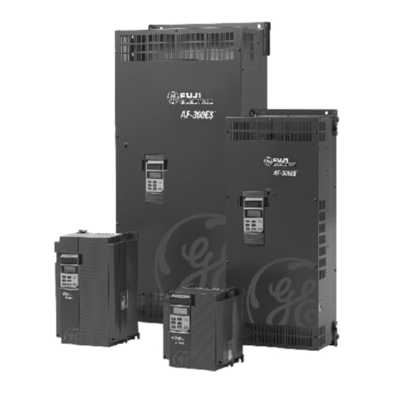
- Page 2 AF-300E$ 1/2 - 350 Horsepower Instructions Artisan Technology Group - Quality Instrumentation ... Guaranteed | (888) 88-SOURCE | www.artisantg.com...
- Page 3 WARNING: Denotes operating procedures and practices sufficiently for the purchaser's purpose, the matter should that may result in personal injury or loss of life if not be referred to GE Fuji, Technical Service. correctly followed. NOTE: The terms "inverter", "controller", and "drive" are CAUTION: Denotes operating procedures and practices sometimes used interchangably throughout the industry.
-
Page 4: Table Of Contents
Table of Contents ACCEL/DECEL Times ..............6-15 1. SAFETY PRECAUTIONS ............1-1 2. DESCRIPTION, COMPONENT IDENTIFICATION, Motor #2 ..................6-16 AND SPECIFICATIONS ..............2-1 Analog Monitor Output ..............6-17 General Description ................. 2-1 Output Terminals ................6-18 Upon Delivery Inspection Procedures ..........2-2 Output Terminal Functions ............. -
Page 5: Safety Precautions
Section 1: Safety Precautions WARNING - WARNING - MECHANICAL MOTION HAZARD: Before disassembling, disconnect and lock out power from Drive systems cause mechanical motion. It is the responsi- the drive. Failure to disconnect power may result in death bility of the user to insure that any such motion does not or serious injury. - Page 6 CAUTION: CAUTION: For RUN and STOP, use the FWD-CM (forward) and REV- Because the ambient temperature greatly affects drive life CM (reverse) terminals. Do not use a contactor (ON/OFF) and reliability, do not install the drive in any location that installed on the line side of the drive for RUN and STOP.
-
Page 7: And Specifications
PHASE ROTATION MAX 60 SEC. AMPS INSTRUCTION BOOK GEI-100211 GE Fuji Drives America Made in Mexico All models are UL Listed and CSA Approved* (Nameplate shown larger than actual size.) Figure 2-1. NAMEPLATE DATA IDENTIFICATION * CE Mark for three-phase (3ø), 415 VAC, 1 to 30 Hp only. -
Page 8: Drive Keypad Functions And Layout
Drive Keypad Functions and Layout Indication of keypad panel operation Digital Monitor (4-digit) Unit displayed LCD Graphic Display Up - Down Keys Run Light Run Key Program Key Shift Key Function/Data Key Reset Key Stop Key Figure 2-2. KEYPAD PANEL COMPONENT IDENTIFICATION Attachment Screws -The Keypad Panel can be easily RUN Key - This key is the RUN command in Keypad op- removed from the Drive unit by loosening the two attach-... - Page 9 Table 1: AF-300E$ – Standard Specifications Environmental Conditions Enclosures NEMA 1 Standard Installation Location Suitable for indoor mounting only, less than 1000 meters (3300 feet) elevation, not in contact with corrosive gas, oil mist, dust, and out of direct sunlight. Stored Temperature -20°...
- Page 10 Frequency Setting Resolution – Analog: 1⁄3000 of max. frequency (0.02 Hz/60 Hz; 0.04 Hz/120 Hz) – Digital: 0.01 Hz (max. frequency up to 99.99 Hz); 0.1 Hz (max frequency of 100 Hz or more) – Analog setting: ± 0.2% of max. frequency (@ 25 ± 10°C) Accuracy (Stability) –...
- Page 11 Operation Frequency Reference Signal – Speed potentiometer/0 to +10 VDC – 4 to 20 mA – 0 to ±10 VDC (Standard on 40 Hp and greater) (Option on 1/2 to 30 Hp) Input Signal (contact type) Forward, reverse, self-holding selection (when operation is 3-wire), multi-step speed setting (7-step), multiple accel/decel time settings (4 settings), coast-to-stop, external alarm, and reset.
- Page 12 Drive Fault – OC1 - Acceleration overcurrent – OC2 - Deceleration overcurrent – OC3 - Constant speed overcurrent – EF - Ground fault – LU (LV) - Undervoltage – OU1 - Overvoltage at accel – OU2 - Overvoltage at decel –...
-
Page 13: Model Numbering System Diagram
AF-300E$ Model Numbering System Diagram Description (X/N)NN GE Product Code AF-300 Drive Family Series Revision 1 = 1st Product Revision 2 = 2nd Product Revision Input Voltage 2 = 230V 50/60 Hz 4 = 460V 50/60 Hz Input Phases 1 = 1 Phase... - Page 14 Table 2: AF-300E$ Drive Dimensions Constant Constant Variable Variable Torque Torque Torque Torque AF-300E$ Catalog List Price H x W x D Weight Hp Rating Rated Output Hp Rating Rated Output Model No. GO-5E$ inches (lbs.) 150% 1 min.* Amps 115% 1 min.* Amps 230 VAC, 3 phase, 50/60 Hz Input, NEMA 1 Enclosure...
- Page 15 AF- UL/CSA 6KE$243025X1B1 D5631 3,200. 300E$ drives. In addition to the new 6KE$243020X1B1 D5632 4,025. CE labeled drives, GE Fuji offers a 6KE$243025X1B1 D5633 4,775. complete compatible line of RFI 6KE$243030X1B1 D5634 5,535. filters.
- Page 16 Table 4: AF-300E$ Drive Ratings Efficiency and Watts Loss Constant Torque Variable Torque Output Current Output Power Efficiency % Watts Loss Watts Loss Catalog No. Const Const 2K Hz 15K Hz 2K Hz 15K Hz 15K Hz Internal 230 VAC - Three Phase 6KE$223F50X1A1 90.0 87.5...
-
Page 17: Installation Guidelines
Section 3: Installation Guidelines Installation Environment CAUTION: Install the drive in an indoor location that meets the following The mounting wall for the drive must be constructed of requirements: heat resistant material because during operation, the ° ° temperature of the Inverter's cooling fins rises to approxi- —... - Page 18 Dimensions 0.5 Hp 230 VAC Dimensions in inches (mm) 4.33 (110) 4.53 (115) 3.78 (96) 0.87 (22) 0.24 (6) 0.28 (7) 0.28 (7) 0.24 (6) 0.24 (6) 2.52 (64) 1.26 (32) 0.87 (22) BUSHING SUPPLIED Artisan Technology Group - Quality Instrumentation ... Guaranteed | (888) 88-SOURCE | www.artisantg.com...
- Page 19 Dimensions 1 Hp 230 VAC Dimensions in inches (mm) 4.33 (110) 512 (130) 3.78 (96) 1.46 (37) 0.28 (7) 0.28 (7) 0.24 (6) 0.24 (6) 0.24 (6) 3.11 (79) 1.26 (32) 0.87 (22) BUSHING SUPPLIED Artisan Technology Group - Quality Instrumentation ... Guaranteed | (888) 88-SOURCE | www.artisantg.com...
- Page 20 Dimensions 2, 3, 5 Hp 230 VAC and 1, 2, 3, 5 Hp 460 VAC Dimensions in inches (mm) 5.91 (150) 5.71 (145) 5.35 (136) 2.05 (52) 0.28 (7) 0.28 (7) 0.24 (6) 0.24 (6) 0.24 (6) 3.7 (94) 1.26 (32) 1.26 (32) 0.87 (22) BUSHING SUPPLIED...
- Page 21 Dimensions 7.5 , 10 Hp 230 and 460 VAC Dimensions in inches (mm) 8.66 (220) 7.68 (195) 7.72 (196) 0.47 (12) 3.82 (97) 0.47 (12) 0.47 (12) 0.39 (10) 0.39 (10) 6.18 (157) 2.07 (52.5) 1.81 (46) 2.26 (57.5) 0.87 (22) BUSHING SUPPLIED Artisan Technology Group - Quality Instrumentation ...
- Page 22 Dimensions 15, 20, 25, 30 Hp 230 and 460 VAC Dimensions in inches (mm) 2-0.39 (10) 9.84 (250) 7.68 (195) 8.90 (226) 0.47 (12) 3.78 (96) 0.47 (12) 0.47 (12) 0.39 (10) 6.02 (153) .0.39 (10) 2.42 (61.5) 2.17 (55) BUSHING SUPPLIED 2.48 (63) 1.34 (34)
- Page 23 Dimensions 35 , 40 Hp 460 VAC Dimensions in inches (mm) BACK PANEL MOUNTING 9.7 (245) 13.4 (340) 2-ø 0.4 (10) 0.1 (2.3) 9.5 (240) AF-300E$ Back-Panel Mounting: Interior Watts Loss Hp (CT) 0 setting 10 setting Hp (VT) 0 setting 10 setting 1100 1050 AF-300E$...
- Page 24 Dimensions 50 Hp 460 VAC Dimensions in inches (mm) BACK PANEL MOUNTING 9.7 (245) 14.8 (375) 2-ø 0.4 (10) 0.1 (2.3) 10.8 (275) AF-300E$ Back-Panel Mounting: Interior Watts Loss Hp (CT) 0 setting 10 setting Hp (VT) 0 setting 10 setting 1200 1150 AF-300E$...
- Page 25 Dimensions 60, 75 Hp 460 VAC Dimensions in inches (mm) BACK PANEL MOUNTING 9.7 (245) 14.8 (375) 2-ø 0.4 (10) 0.1 (2.3) 10.8 (275) AF-300E$ Back-Panel Mounting: Interior Watts Loss Hp (CT) 0 setting 10 setting Hp (VT) 0 setting 10 setting 1000 1300 1050...
- Page 26 Dimensions 100 Hp 460 VAC Dimensions in inches (mm) BACK PANEL MOUNTING 106 (270) 14.8 (375) 2-ø 0.4 (10) 0.1 (2.3) 10.8 (275) AF-300E$ Back-Panel Mounting: Interior Watts Loss Hp (CT) 0 setting 10 setting Hp (VT) 0 setting 10 setting AF-300E$ 1500 1600...
- Page 27 Dimensions 125 Hp 460 VAC Dimensions in inches (mm) BACK PANEL MOUNTING 12.4 (315) 20.9 (530) 2-ø 0.6 (15) 0.1 (3.2) 16.9 (430) AF-300E$ Back-Panel Mounting: Interior Watts Loss Hp (CT) 0 setting 10 setting Hp (VT) 0 setting 10 setting AF-300E$ 1750 2000...
- Page 28 Dimensions 150 Hp 460 VAC Dimensions in inches (mm) BACK PANEL MOUNTING 14.2 (360) 20.9 (530) 2-ø 0.6 (15) 0.1 (3.2) 16.9 (430) AF-300E$ Back-Panel Mounting: Interior Watts Loss Hp (CT) 0 setting 10 setting Hp (VT) 0 setting 10 setting 2050 2350 2050...
- Page 29 Dimensions 200 Hp 460 VAC Dimensions in inches (mm) BACK PANEL MOUNTING 14.2 (360) 20.9 (530) 2-ø 0.6 (15) 0.1 (3.2) 16.9 (430) AF-300E$ Back-Panel Mounting: Interior Watts Loss Hp (CT) 0 setting 10 setting Hp (VT) 0 setting 10 setting 2850 3250 2800...
- Page 30 Dimensions 250, 300 Hp 460 VAC Dimensions in inches (mm) BACK PANEL MOUNTING 14.2 (360) 26.8 (680) 2-ø 0.6 (15) 4.5 (115) 22.8 (580) AF-300E$ Back-Panel Mounting: Interior Watts Loss Hp (CT) 0 setting 10 setting Hp (VT) 0 setting 10 setting AF-300E$ 3500 4000...
- Page 31 Keypad Mounting Hole (Panel Cutting) Dimensions in inches (mm) 3-15 Artisan Technology Group - Quality Instrumentation ... Guaranteed | (888) 88-SOURCE | www.artisantg.com...
- Page 32 Notes: 3-16 Artisan Technology Group - Quality Instrumentation ... Guaranteed | (888) 88-SOURCE | www.artisantg.com...
-
Page 33: Wiring Procedures
Section 4: Wiring Procedures WIRING PROCEDURES CONTROL CIRCUIT WIRING REMOVE TERMINAL BLOCK COVER drive is wired at shipment for operation and frequency Remove the terminal block cover as follows setting through the keypad panel (frequency is set at 60 Hz.) (see Figure 4-1): –... -
Page 34: Main Circuit Wiring
MAIN CIRCUIT WIRING CAUTION: Be sure that the power supply is never connected to the U, 3. Connect the 3-phase motor wires to the U, V, and W V, W terminals or the N, P, DB terminals. terminals of the Main Circuit Terminal Block as shown in the appropriate view of Figure 4-3 or 4-4. - Page 35 1 Device ratings such as system coordination, short-circuit rating and type must be carefully reviewed by the user. 2 Based on GE Fuji DB resistor designs. Other ratings require careful review. 3 Device ratings such as system coordination, short-circuit rating and type must be carefully reviewed by the user.
- Page 36 Control Terminal Board 1⁄2 - 30 Hp CAUTION Remove Jumper from between terminals THR and CM when thermal interlocks are used. NOTE Wiring connections for operation with kaypad reference control. CM-FWD and CM-THR terminals are jumpered together at the factory. Power Terminal Board FUSES: Reference UL power circuit...
- Page 37 Control Terminal Board 40 - 300 Hp CAUTION Remove Jumper from between terminals THR and CM when thermal interlocks are used. CAUTION Remove jumper from between terminals FWD and CM. NOTE Wiring connections for operation with kaypad reference control. CM-FWD and CM-THR terminals are jumpered together at the factory.
- Page 38 1⁄2 to 30 Hp AF-300E$ Drive Rating Circuit Breaker 380/460 VAC Main Motor 3PH AC Input 50/60 Hz Power Ground Speed Pot 1-5K Ohm CURRENT 4 TO Braking Section ** 20 mA 1/2 to 10 HP E(G) Frequency Meter 10V (Movable coil type 10V) Braking Resistor Thermal Switch...
- Page 39 40 to 300 Hp AF-300E$ Drive Rating Curcuit Breaker 380/460 VAC Control Main 460V Power Motor Power 3PH AC Input Input 50/60 Hz Ground Braking Section ** Speed Pot VOLTAGE CURRENT 1-5K Ohm 0 TO 4 TO ± VDC 20 mA E(G) Braking Unit Braking Resistor Run Relay...
- Page 40 Table 5: Terminal Identification/Function Terminal Terminal Label Name Function POWER TERMINAL BOARD L1, L2, ac Supply Line Connection for commercial power (200-230 VAC or 380-460 VAC); Input Terminals 3-phase; 50⁄60 Hz. U, V, W Drive Output Connection for 3-phase induction motor. Terminals P+, DB External Braking...
- Page 41 Table 5: Terminal Identification/Function (continued) Terminal Terminal Label Name Function Control Terminal Board Cont'd 3-wire Operation - When 3-wire operation is selected and HLD-CM is closed, the pulse Stop Command signal input from FWD, REV terminals is held internally. (Operation From Momentary Contacts) Reset Signal Input After removal of fault condition, Faults are reset when a momentary...
-
Page 42: Auxiliary Controlpower Supply Connection
Auxiliary ControlPower Supply Connection DC Link Reactor Connection When using the circuit shown in Figure 4-8, it is necessary A DC Reactor is required on all AF-300 drives rated 100 Hp to connect terminals "RO" and "TO" to the line side of the and above. - Page 43 Remote Operation 30A 30B Y1 C1 FMA FMP X1 X5 RST CM FWD REV CM THR HLD BX 30C CME Y2 STOP 01=1 (REMOTE) NOTE: JOG ACCEL TIME SETTING CONTACT BETWEEN FWD AND JOG DECEL TIME SETTING CM MUST BE OPEN DURING JOG SPEED (FREQUENCY) SETTING POWER-UP OR "Er6"...
-
Page 44: Automatic Restart Circuit Connection
Automatic Restart Circuit Connection Drive Interface Details 27 VDC MAX 50 mA MAX OUTPUT TERMINALS Y1 – Y5 Figure 4-11. AUTOMATIC RESTART CIRCUIT CONNECTIONS — Timer setting (T ) is fixed in software at 5 seconds. — Timer starts after an initializing time of 2 seconds maximum when power returns. - Page 45 Dynamic Braking Braking Torque CT Applications VT Applications Dynamic Model No. Built in Optional Duty Brake Duty Brake Braking DB Resistor Total Resistor Resistor Factor Time Factor Time Module Reqd Model Reqd Ohms 230 VAC, 3 Phase, 60 Hz Input Power 6KE$223F50X1A1 100% 150%...
-
Page 46: Main Circuit Wiring For Ce Mark
Main Circuit Wiring for CE Mark Connect the power supply of overvoltage category 2 to the main power input terminals L1, L2 and L3 via a circuit breaker and/or a leakage current breaker. There is no need to match the phase when connecting. If the power supply is overvoltage category 3, place the devices to limit overvoltage below 2.5 kV as shown. -
Page 47: Pre-Operation Inspection
Section 5: Drive Operation Drive Operation Table 6: Keypad and Display Operation Programming Pre-operation Inspection After mounting and wiring has been completed, check the Keypad Panel drive for the following items before applying AC power: — Check for wiring errors (especially main circuit wiring). —... -
Page 48: Program Mode Example Of Changing A Function Code
Program Mode Example of Changing a Function Code LCD Graphic Display at Power Up. STOP Press UP Key to Increase DATA SET Accel Time. >> Key Can >> LED SEL Shift Decimal Point. ACC TIME 1 Press PRG Key to 6.00S Display Function Codes 10.00S... -
Page 49: Program Mode - Example Of Checking Function Codes
Program Mode Example of Checking Function Codes (Also Allows Changing Settings) LCD Graphic Display at Power Up STOP Press FUNC/DATA Key to DATA SET indicate setting and range >> LED SEL of setting. ACC TIME 1 6.00S Press FUNC/DATA Key 0.01 3600 ˜... -
Page 50: Program Mode Checking Input/Output Signals
Program Mode Checking Input/Output Signals LCD Graphic Display at Power Up STOP FMA = 0.0 V DATA SET FMP = 0.0 V >> LED SEL FMP = 0 Hz Press FUNC/DATA Key Press >> Key to Display Operating Time to Display Program and Version Numbers. -
Page 51: Keypad Fault Indication
Keypad fault indication LCD Graphic Display at Power Up STOP DATA SET >> LED SEL : ON PressFUNC/DATA key to : OFF display Program Mode. Press >> key to display output terminal status. DATA CHECK I/O CHECK TRIP IND CK TRIP FACTOR Press >>... - Page 52 Circumstances of Trip Press >> key to TIME = TRQ = °C TEMP = Exploded view of Circumstances of Trip Display (from previous page.) The above drawing shows the spacing of the display. Conditions at Fault Blank – Normal Operation Forward Direction Reverse Direction Normal Condition...
-
Page 53: Display At A Fault
Display at a Fault LED Display on Digital Monitor LCD Graphic Display UNDER VOLTAGE FACTOR >> ITEM SEL Press >> Key to Display Status of the Trip. RESET Fout = Press FUNC/DATA Key to Indicate Fref Operating Conditions to be reviewed. Iout Vout = LOW SUP V... -
Page 54: Accessing Fault History
Accessing Fault History STOP DATA SET >> LED SEL Press FUNC/DATA Key to Display Program Mode. DATA CHECK I/O CHECK TRIP IND CK TRIP FACTOR Press DOWN Key to scroll to Trip Indication Check. DATA CHECK I/O CHECK TRIP IND CK TRIP FACTOR Press FUNC/DATA Key to Display the last 3 Faults... - Page 55 Notes Artisan Technology Group - Quality Instrumentation ... Guaranteed | (888) 88-SOURCE | www.artisantg.com...
- Page 56 Table 7: Function Code Settings Function Code Numbers Followed by Function Descriptions * Function can be changed while the Drive is operating. Analog Monitor Output Basic Functions (cont'd) Basic Functions * Multistep Frequency * FMP Terminal Pulse Rate Frequency Command Setting 4 Multiplier Operation Method...
- Page 57 Special Functions (cont'd) LED & LCD Monitor Motor Characteristics * LED Monitor (Function) Motor 1 (Capacity) * LED Monitor (Display at Stop Mode) Motor 1 (Rated Current) * Coefficient for Line Speed Motor 1 (No Load Current) * LCD Digital Monitor Selection Motor 2 (Rated Current) Pattern Operation Motor 1 Impedance...
- Page 58 Notes 5-12 Artisan Technology Group - Quality Instrumentation ... Guaranteed | (888) 88-SOURCE | www.artisantg.com...
-
Page 59: Function Code Descriptions
GRAPHIC FACTORY Section 6: Function Code Descriptions FUNCTION DISPLAY SETTING DESCRIPTION SETTING BASIC FUNCTIONS NOTE: * = Function can be changed while the Drive is operating. GRAPHIC FACTORY FUNCTION DISPLAY SETTING DESCRIPTION SETTING FREQ COMND FREQUENCY COMMAND Frequency reference can be supplied by three different methods: Keypad (digital), 0 to +10 VDC, 4 to 20 mA. - Page 60 GRAPHIC FACTORY FUNCTION DISPLAY SETTING DESCRIPTION SETTING MAX Hz MAXIMUM HERTZ Maximum output frequency is adjustable from 50 Hz to 400 Hz in 1 Hz steps. Maximum frequency WARNING: Review motor capabilities for operation above motors's base frequency. BASE Hz-1 BASE FREQUENCY #1 Base frequency for motor #1 is adjustable from 30 Hz to 400 Hz in 1 Hz steps.
- Page 61 GRAPHIC FACTORY FUNCTION DISPLAY SETTING DESCRIPTION SETTING * 07 TRQ BOOST1 TORQUE BOOST #1 Torque boost for motor #1 can be set to optimize the V/Hz characteristics of the drive according to the type of load the motor will see. The factory setting of zero (0) causes the drive to automatic- ally select the boost level according to its torque calculations...
- Page 62 GRAPHIC FACTORY FUNCTION DISPLAY SETTING DESCRIPTION SETTING Forced air cooled mo * 08 (cont'd) NOTE: If the carrier frequency is set higher than 10 KHz and an internal overheating condition occurs, the drive will auto- matically reduce the carrier frequency to 10 KHz in order to avoid an overheating fault (available up to 30 Hp only).
- Page 63 GRAPHIC FACTORY FUNCTION DISPLAY SETTING DESCRIPTION SETTING (cont'd) Restart inactive - Drive will trip and alarm when low voltage point is detected. Restart inactive - Drive will trip but will not alarm until voltage recovers. Restart active - Normal smooth recovery method: drive will continuously decrease speed until voltage recovers, then accelerate normally back to set point.
- Page 64 GRAPHIC FACTORY FUNCTION DISPLAY SETTING DESCRIPTION SETTING * 13 FREQ BIAS FREQUENCY BIAS Frequency bias is an offset which is added to the frequency set point when an analog reference is selected. This will allow for improved resolution when adjust- ment over the entire speed range is not required.
- Page 65 GRAPHIC FACTORY FUNCTION DISPLAY SETTING DESCRIPTION SETTING * 14 FREQ GAIN FREQUENCY GAIN 100.0 Frequency gain is a multiplier on the frequency set point when an analog refer- ence is selected (100% equals unity gain). Adjustable from 0 to 200%. 200% 100% Output...
- Page 66 GRAPHIC FACTORY FUNCTION DISPLAY SETTING DESCRIPTION SETTING * 16 BRK TORQUE BRAKING TORQUE This limit puts a hard clamp on the amount of torque which the drive will provide in the braking direction (i.e. absorbing power). It is set as a percentage of rated torque and is adjustable from 20 to 180%.
- Page 67 GRAPHIC FACTORY FUNCTION DISPLAY SETTING DESCRIPTION SETTING * 19 DC BRK t DC INJECTION BRAKING TIME "ON" 0.0S The dc injection brake time is adjustable from 0.1 to 30.0 seconds using this setting. A setting of zero (0) causes dc braking to be inactive.
- Page 68 GRAPHIC FACTORY FUNCTION DISPLAY SETTING DESCRIPTION SETTING MULTI STEP FREQUENCIES (Cont'd) Speed Output Frequency Speed Speed Speed Speed Speed Speed Analog Digital X1-CM X2-CM X3-CM FWD-CM NOTES: – When X1 – CM, X2 – CM, and X3 – CM are all OFF, frequency reference is set by keypad (/\ \/ keys) or by the analog inputs per Function Code 00 setting.
- Page 69 GRAPHIC FACTORY FUNCTION DISPLAY SETTING DESCRIPTION SETTING * 28 SLIP COMP SLIP COMPENSATION Slip compensation provides a means of improving speed accuracy without employing speed feedback (i.e. open-loop method). It does this by adjusting output frequency as a function of load and can be expected to im- prove speed fluctuations to within 1/3 of normal slip.
- Page 70 For your convenience we have pre-installed the parameters for the 4-pole GE Energy $aver® motor with horsepower rating corresponding to the drive rating. If you are using any other motor you should set...
-
Page 71: Input Terminal Functions
GRAPHIC FACTORY FUNCTION DISPLAY SETTING DESCRIPTION SETTING MTR POLES MOTOR POLES The number of motor poles is set only for the display of synchronous RPM. It has NO effect on drive operation. Adjustable from 2 to 14 (even numbers only). 2 Poles 3600 RPM 4 Poles... - Page 72 GRAPHIC FACTORY FUNCTION DISPLAY SETTING DESCRIPTION SETTING 32 (cont'd) X4 - function selected by 3rd digit: - - 0 - ACC/DEC time selection (two steps) - - 1 - Selects 4 to 20 mA as an input for frequency reference at terminal (C1) (will ignore speed pot, V1 inputs and keypad) - - 2 - DC brake command (can be used to maintain...
-
Page 73: Accel/Decel Times
X5 to CM contacts open - Protected (Change prevented) X5 to CM contacts closed - Not Protected (Changeable) - - - 3 Restart Function NOTE: In order to bypass GE Safety software (Er6), select "3" and install a wire jumper between Terminal X5 and CM. ACCEL/DECEL TIMES... -
Page 74: Motor #2
GRAPHIC FACTORY FUNCTION DISPLAY SETTING DESCRIPTION SETTING MOTOR #2 NOTE: Motor #2 is a second motor NOT multi-motor. BASE Hz-2 BASE FREQUENCY #2 Base frequency for motor #2 is adjustable from 30 Hz to 400 Hz in 1 Hz steps. Motor #2 Function Codes become active when Function Code 32 equals - - 1 and X5 –... -
Page 75: Analog Monitor Output
GRAPHIC FACTORY FUNCTION DISPLAY SETTING DESCRIPTION SETTING ANALOG MONITOR OUTPUT * 43 FMP PULSES FMP FREQUENCY PULSE OUTPUT The FMP terminal provides a pulse whose output is proportional to drive output frequency. The number of pulses per second is given as output Hz multiplied by the setting in Function Code 43 with a maximum output of 6,000 pulses per second. -
Page 76: Output Terminals
GRAPHIC FACTORY FUNCTION DISPLAY SETTING DESCRIPTION SETTING * 46 FMA FUNC FMA OUTPUT INDICATION This Function Code selects the quantity to be displayed via the analog output between the FMA and II terminals. Output frequency (0 to 100% full scale) Output current (0 to 200% full scale) Output torque (0 to 200% full scale) Output power (0 to 200% full scale) - Page 77 GRAPHIC FACTORY FUNCTION DISPLAY SETTING DESCRIPTION SETTING 47 (cont'd) Stage number indication for Pattern Operation, requires Y3, Y4, and Y5 outputs, set Function Code 47 equal - - EEE. Stage Alarm indication in alarm trip mode, requires Y2, Y3, Y4, and Y5 outputs, set Function Code 47 equal - FFFF.
-
Page 78: Output Terminal Functions
GRAPHIC FACTORY FUNCTION DISPLAY SETTING DESCRIPTION SETTING OUTPUT TERMINAL FUNCTIONS * 48 FAR HYSTR FREQUENCY AT REFERENCE HYSTERESIS (WIDTH) The signal is on when the output frequency equals the frequency reference’s set point. This is an open collector output and can be used in conjuction with a relay unit to allow connection to system control circuitry. - Page 79 GRAPHIC FACTORY FUNCTION DISPLAY SETTING DESCRIPTION SETTING * 50 FDT HYSTR FREQUENCY DETECTION HYSTERESIS The setting is the offset that FDT will have from the FDT level. Adjustable from 0.0 to 30 Hz. Output FDT Level Frequency FDT Hyster Signal * 51 OL WARNING OVERLOAD EARLY WARNING...
-
Page 80: Frequency Control
GRAPHIC FACTORY FUNCTION DISPLAY SETTING DESCRIPTION SETTING FREQUENCY CONTROL These Function Codes are used to avoid the natural mechanical vibration of the load. The three jump frequencies can be set independently and are adjustable from 0 to 400 Hz. JUMP Hz-1 FREQUENCY JUMP SETTING JUMP Hz-2 FREQUENCY JUMP SETTING... - Page 81 GRAPHIC FACTORY FUNCTION DISPLAY SETTING DESCRIPTION SETTING START Hz START FREQUENCY Starting frequency set range is adjustable from .2 to 60 Hz (used to optimize available starting torque.) Output Frequency Holding time 0 - 10 sec. Start Freq. 0.2 to 60 Hz HOLDING t START FREQUENCY HOLD TIME A starting frequency and holding time can...
-
Page 82: Led & Lcd Monitor
GRAPHIC FACTORY FUNCTION DISPLAY SETTING DESCRIPTION SETTING LED & LCD MONITOR * 61 LED MNTR 1 LED MONITOR SELECTION #1 Setting from 0 to 8 for a total of nine (9) selectable indicating modes. See table below: Setting Running When speed is controlled from KEYPAD (00=0), Stopping Unit displays changes to indication below if speed is changed... - Page 83 GRAPHIC FACTORY FUNCTION DISPLAY SETTING DESCRIPTION SETTING * 64 LCD MNTR LCD GRAPHIC DISPLAY SELECTION LCD GRAPHIC DISPLAY is selectable from the the following: RUN or STOP STOP DATA SET DATA SET >> LED SET >> LED SET Bar graph (set frequency and output frequency) Stop 100% 100%...
-
Page 84: Pattern Operation
GRAPHIC FACTORY FUNCTION DISPLAY SETTING DESCRIPTION SETTING PATTERN OPERATION PATTERN PATTERN OPERATION A pattern operation can be set for seven (7) individually set speeds (Function Codes 20 through 26) to run up to 6,000 seconds each, forward or reverse direction (Function Codes 66 through 72) with the following choice of cycles: Inactive... - Page 85 GRAPHIC FACTORY FUNCTION DISPLAY SETTING DESCRIPTION SETTING Pattern Operation (cont’d) NOTES : – When Function Code 65 is set to 1, 2 or 3, pattern operation is made possible by setting the multi-step frequency combination of stages 1 through 7 (Function Codes 66 through 72).
- Page 86 GRAPHIC FACTORY Example 1: when Function Code is 67 (stage 2) 5.00 F1. FUNCTION DISPLAY SETTING DESCRIPTION SETTING Stage 2 Stage 1 Stage 1 Stage 2 Example 2: when Function Code is 67 (stage 2) is set at 5.00R1. Stage 1 Forward Reverse Stage 2...
- Page 87 GRAPHIC FACTORY Pattern Operation Method #1: Keypad Panel FUNCTION DISPLAY SETTING DESCRIPTION SETTING The key functions are changed as follows: RUN key: Start operation STOP key: Temporary stop of drive operation (pause) RESET key: Resets pattern to original starting point. The next RUN input will start operation from pattern stage 1.
- Page 88 GRAPHIC FACTORY PATTERN OPERATION METHOD #2: CONTROL TERMINAL BOARD FUNCTION DISPLAY SETTING DESCRIPTION SETTING “REMOTE” The terminal functions are changed as follows: FWD-CM = ON :Start operation FWD-CM = OFF :Stops timer operation (Pause) RESET key :Timer reset NOTE: The RESET key only functions when the drive is stopped or paused.
-
Page 89: Special Functions
GRAPHIC FACTORY FUNCTION DISPLAY SETTING DESCRIPTION SETTING ACC PTN ACCELERATION/DECELERATION PATTERN Selection can be made from the following types: Linear acceleration/deceleration (Fig. a) S curve acceleration/deceleration (Fig. b) Non-linear for variable torque load (Fig. c) Fig. A Fig. C Fig. B Output Output Output... - Page 90 GRAPHIC FACTORY FUNCTION DISPLAY SETTING DESCRIPTION SETTING * 79 BRIGHTNESS LCD GRAPHIC DISPLAY MONITOR BRIGHTNESS 1 TO 10 Bright (1) to Dark (10) * 80 81-94 FUNCTION CODE BLOCK DISPLAY This setting determines whether or not Function Codes 81 through 94 will be displayed and available for adjustment.
-
Page 91: Motor Characteristics
GRAPHIC FACTORY FUNCTION DISPLAY SETTING DESCRIPTION SETTING * 85 RESET INT RESET INTERVAL Time interval between reset attempts as set in Function Code 84. 2 TO 20 Time in seconds. MOTOR CHARACTERISTICS MOTOR CAP MOTOR Hp CAPACITY This Function Code is used to select the motor Hp capacity in relation to the drive Hp capacity. - Page 92 GRAPHIC FACTORY FUNCTION DISPLAY SETTING DESCRIPTION SETTING * 91 %R1 SET MOTOR #1 CALCULATED % PER UNIT RESISTANCE 0.00 TO Percent of motor resistance. 50.00 %: %R1 = R1 + Cable R x 100 √ V/ ( 3 x I) R1 is motor resistance;...
-
Page 93: Maintenance And Inspection
Section 7: Maintenance and Inspection So that the AF-300E$ drive may give long periods of PERIODIC PARTS REPLACEMENT trouble-free operation and to prevent potential problems The life of the drive will vary according to the installation from occuring, the following items should be periodically environment and the amount of running time. -
Page 94: Measurement Points And Meters
INSPECTION ITEMS CHART Item Inspection Criteria Corrective Action Power Source Within permissible limits (170 - 253 VAC) Adjust the power supply voltage Voltage for 230 VAC drives; or (323 - 506) for 460 VAC drives; or (480-575) for 575 VAC drives. Ambient Within permissible limits (-10 to +50... - Page 95 Figure 7-2. MEASUREMENT LOCATIONS AND DEVICES EXAMPLE Artisan Technology Group - Quality Instrumentation ... Guaranteed | (888) 88-SOURCE | www.artisantg.com...
- Page 96 Notes: Artisan Technology Group - Quality Instrumentation ... Guaranteed | (888) 88-SOURCE | www.artisantg.com...
-
Page 97: Troubleshooting
Section 8: Troubleshooting TABLE 11: Fault Condition Description and Operation The following GE AF-300E$ drive protection functions have been incorporated in the basic drive software and will be indicated in the LED display as well as listed in the fault table display. -
Page 98: Fault Condition Display And Corrective Actions
FAULT CONDITION DISPLAY AND CORRECTIVE ACTION CAUTION: CAUTION: Do not conduct any inspection until after disconnecting the Electrostatic Discharge: The AF-300E$ has components power supply and after the "CHG" light on the drive has gone and board assemblies that are sensitive to electrostatic out. -
Page 99: Ground Fault
Protective Alarm RY Function Explanation Remarks Function Display (30A, B & C) Ground Fault Grounded output. The protecction is effective for Drive output Grnd terminals - U, V, W. Fault GROUND FAULT EF, (during CONST. SPD) Operating conditions that need to be reviewed: Drive GROUND FAULT Display... -
Page 100: Temperatures, Etc
Protective Alarm RY Function Explanation Remarks Function Display (30A, B & C) Over heat Protects the Drive against overheating caused by O H 1 Fin temp. overload operation, cooling fan failure, abnormal high ambient O H 3 Internal temperatures, etc. temp. -
Page 101: Electronic Protects The Drive With Electronic Overload
Protective Alarm RY Function Explanation Remarks Function Display (30A, B & C) Electronic Protects the Drive with electronic overload. O L U thermal Protects the motor with electronic overload sense overload Range of setting: 20 to 135% of Drive rated current. OVER LOAD OL (Motor Overload), Operating conditions that need to be reviewed: Drive EXCESS LOAD... -
Page 102: External Stops Drive By An External Alarm Signal. O H
Protective Alarm RY Function Explanation Remarks Function Display (30A, B & C) External Stops Drive by an external alarm signal. O H 2 OVER HEAT OH2 (external equip. alarm), Operating conditions that need to be reviewed: Drive THR OPEN Display Protective Alarm RY Function Explanation... - Page 103 Protective Alarm RY Function Explanation Remarks Function Display (30A, B & C) CPU error Detection of a CPU malfunction. E r 3 CPU RUNAWAY Er 3 (drive), Operating conditions that need to be reviewed: Drive ELEC NOISE Display HARDWARE MALF Protective Alarm RY Function Explanation...
- Page 104 Protective Alarm RY Function Explanation Remarks Function Display (30A, B & C) Operating Detects Drive operating procedure error during Drive startup. E r 6 Proc. Error FWD or REV connected to terminal CM at time of main power being applied to Drive. Stop keypad in remote operation. TUNING ERROR Er 6, Operating conditions that need to be reviewed: Drive SEE MANUAL...
- Page 105 ( 2 ) Ground Fault Is drive output There is the possibility of failure in grounded? the drive or a noise problem. Please contact GE Fuji Repair short-circuit and/or grounding sections. Artisan Technology Group - Quality Instrumentation ... Guaranteed | (888) 88-SOURCE | www.artisantg.com...
- Page 106 Is the braking unit and braking resistor installed and activated? Investigate braking unit, braking resistor or DC brake for correct connection rating and control settings. Review the control and system application again. Contact GE Fuji 8-10 Artisan Technology Group - Quality Instrumentation ... Guaranteed | (888) 88-SOURCE | www.artisantg.com...
- Page 107 Contact GE Fuji. Note 1 – When the DC bus capacitor is discharged by a system power failure and the control power of the drive is reduced,automatic restart after momentary power outage may take place. (Refer to Function Code 10 setting.) When the Function Codes 82, 83, 84 and 85 are selected, no resetting is required.
-
Page 108: External Failure
Failure in the drive or noise related Is the ambient misoperation can be temperature within considered. the specified limit? Contact GE Fuji Bring the ambient condition to within the specified limit. ( 6 ) External failure O H 2 Is the connection... -
Page 109: Overload
GE Fuji capacity ( 8 ) DC Link fuse blown F U S Short circuit might be in the drive. Contact GE Fuji 8-13 Artisan Technology Group - Quality Instrumentation ... Guaranteed | (888) 88-SOURCE | www.artisantg.com... - Page 110 Check for contami- nation due to the The drive is environment. operational. This is referable to failure in the drive. Contact GE Fuji ( 10 )Tuning error E r 7 Connect wires or Output circuit U,V,W, disconnected or open change wires. circuit.
-
Page 111: Motor Will Not Run
The drive is for ground in terminals (U, V, W) thought to have reference circuit. have applied failed. Contact voltage? GE Fuji. Correct wiring. Is the wiring to the motor connected properly? Release the Has the motor Is the load too Has the torque lock. -
Page 112: Motor Will Run But Speed Will Not Change
Contact GE Fuji Change the setting to the time suitable for the load. Motor speed change is very small under these conditions: 1. Wrong setting of FC13 bias frequency, FC14 gain for frequency setting. -
Page 113: Motor Will Stall During Acceleration
( 13 ) Motor will stall during acceleration. The motor will stall during acceleration. Increase the set Is the acceleration time. time setting short? Contact GE Fuji Is Wk of the motor Is a special and/or load motor in use? excessive? Reduce the load Wk increase the drive capacity. -
Page 114: Control Block Diagram
AF-300E$ Adjustable Frequency Drive Control Block Diagram 8-18 Artisan Technology Group - Quality Instrumentation ... Guaranteed | (888) 88-SOURCE | www.artisantg.com... -
Page 115: Warranty Parts And Service
Salem, VA Motor repairs on General Electric motors are generally (540) 387-5739 handled by GE Authorized Electric Motor Servicenters or (8 AM to 5 PM EST, Mon. thru Fri.) GE Apparatus Service Shops. For specific instructions on your motor, call the distributor from which it was purchased and be prepared to furnish complete nameplate data. -
Page 116: In-Warranty Failure Checklist
When returning failed parts, reference the C_ _ _ _# on the shipping documents that came with the replacement parts and ship failed parts to: GE Fuji Drives USE, Inc. • Attn: Product Service Dept. • Rm 191 • 1501 Roanoke Boulevard • Salem, VA 24153 (Marked C_ _ _ _ # ) -
Page 117: Replacement Parts
Section 10: Replacement Parts Catalog No. Rating Drive horsepower & quantity per drive L" x W" x H" Weight 7.5 10 15 20 25 30 lbs. AF-300E$ 230 VAC, 30 Hp and Below Main Control Card G9CPCBG204 4 x 5.75 x 1.25 0.23 G9CPCBG2075 4 x 5.75 x 1.25... - Page 118 Catalog No. Rating Drive horsepower & quantity per drive L" x W" x H" Weight 7.5 10 15 20 25 30 lbs. AF-300E$ 230 VAC, 30 Hp and Below (continued) Fuse Cr6L150/UL 150A 1.5 x 4 x 1.5 0.14 Cr6L260/UL 260A 1.5 x 4 x 1.5 0.14...
- Page 119 Catalog No. Rating Drive horsepower & quantity per drive L" x W" x H" Weight 7.5 10 15 20 25 30 lbs. AF-300E$ 460 VAC, 30 Hp and Below (continued) Diode Module CVM40CD160 40A 1600V 4 x 2 x 1 0.46 CVM50BB160 50A 1600V...
- Page 120 Catalog No. Rating Drive horsepower & quantity per drive L" x W" x H" Weight 35 40 50 60 75 100 125 150 200 250 300 lbs. AF-300E$ 460 VAC, 40 Hp and Above (continued) Hall Effect Current Transformer NC10GET 40MV/60AT 2 x 1.25 x 1.25 0.10...
- Page 121 Catalog No. Rating Drive horsepower & quantity per drive L" x W" x H" Weight 35 40 50 60 75 100 125 150 200 250 300 lbs. AF-300E$ 460 VAC, 40 Hp and Above (continued) Keypad Assembly HF5A2685B 9.5 x 4.75 x 3.5 0.45 0.21 Keypad...
- Page 122 Notes 10-6 Artisan Technology Group - Quality Instrumentation ... Guaranteed | (888) 88-SOURCE | www.artisantg.com...
-
Page 123: Glossary - Drives Terminology
Section 11: Glossary - Drives Terminology C. Squirrel-cage Motor Dynamic Braking - “DC Injection Brak- The following are standard definitions of terms that are used when discussing adjustable frequency drives: ing” (This form is not the same as that noted for AC drives.) It is another form of braking which uses a control circuit that +BUS: +Bus is the portion of the DC bus that is at a positive applies a dc voltage across the ac motor’s stator windings... - Page 124 Constant Torque Range: A speed range in which the motor is Drift: Drift is the deviation from the initial set speed with no capable of delivering a constant torque, subject to motor load change over a specific time period. Normally the drive thermal characteristics.
- Page 125 Feedback: The element of a control system that provides an Induction Motor: An alternating current motor in which the actual operation signal for comparison with the set point to primary winding on one member (usually the stator) is con- establish an error signal used by the regulator circuit. nected to the power source.
- Page 126 Linear Acceleration/Deceleration: A circuit that controls the Overload Capacity: The ability of the drive to withstand cur- rate at which the motor is allowed to accelerate to a set rents beyond the systems continuous rating. It is normally speed or decelerate to zero speed. On most drives, this specified as a percentage of full load current for a specified circuit is adjustable and can be set to accommodate a par- time period.
- Page 127 PLC (Programmable Logic Controller): Solid-state control SCR (Silicon Control Rectifier): A solid state device that has logic for machines and processes where a sequence of an anode, a cathode, and gate which controls when it al- operations can be changed easily with programming lows conduction.
- Page 128 Synchronous Speed: The speed of an AC induction motor’s Transducer: A device that converts one energy form to an- rotating magnetic field. It is determined by the frequency other (e.g. mechanical to electrical). Also, a device that applied to the stator and the number of magnetic poles when actuated by signals from one or more systems or present in each phase of the stator windings.
-
Page 129: Electromagnetic Compatibility
European Commission Guidelines Document on Council limit RF current flowing into the main AF-300E$ supply Directive 89/336/EEC GE Fuji had chosen to classify the circuit. Without an input filter a AF-300E$ installation may AF-300E$ range of drives as “Complex Components”. - Page 130 Table 12-1 RFI filter dimensions Conforms to EN55011 Class B Filter Rated Max. Dimension Mounting Dim. Drive Required Part Applied Drive Current Rated L x W x H X, Y Fixing Sub Filter Voltage inches (mm) inches (mm) EFL-1.5 G9-4 6KE$243001X1B1 5.5A 12.2 x 6.1 x 1.8 4.1 x 11.6...
- Page 131 Basic Standard: EN55011 Class B Enclosure 3-Phase 50/60 Hz Power Ferrite Ring Supply Input Through Contactor 1 turn Screen Noise Filter HRC Fuses (Footmount) Drive or Circuit Breaker L1’ L2’ L3’ Max. 33 feet Screening must be electrically continuous and grounded at the Enclosure and the motor.
- Page 132 DB-resistor Power factor correcting Enclosure DC reactor 2 THR E P BD 1 CM Power Supply 3ø P( + ) DB N( - ) Ferrite Ferrite RFI Filter 380-415v Ring Ring 50/60Hz Motor L1‘ L2‘ L3‘ Armoured or Screened Cable [13] Frequency setting [12]...
- Page 133 When: Wired and grounded with the installation instructions. Installed within a steel enclosure. Used in conjunction with power input filter and ferrite rings which are recommended by GE Fuji Drives. EC Declaration of Conformity We GE Fuji Drives declare under our sole responsibility that the following products Product Identification •...
- Page 134 Notes 12-6 Artisan Technology Group - Quality Instrumentation ... Guaranteed | (888) 88-SOURCE | www.artisantg.com...
- Page 135 GE Fuji Drives USA GE Fuji Drives America, 1501 Roanoke Boulevard S.A. de C.V. Room 435 Ave.La Sierra 1401 Salem, VA 24153 Parque Industrial La Silia Internet Address: Guadalupe, N.L. GEI-100211G (12/98) http://www.ge.com Mexico 67190 Artisan Technology Group - Quality Instrumentation ... Guaranteed | (888) 88-SOURCE | www.artisantg.com...