Siemens SITRANS LR560 Operating Instructions Manual
Radar transmitters (foundation fieldbus)
Hide thumbs
Also See for SITRANS LR560:
- Quick start manual (270 pages) ,
- Operating instructions manual (222 pages) ,
- Compact operating instructions (66 pages)

Related Manuals for Siemens SITRANS LR560


Summary of Contents for Siemens SITRANS LR560
- Page 1 Operating instructions SITRANS Radar transmitters SITRANS LR560 (FOUNDATION FIELDBUS) Edition 06/2018 www.siemens.com/processautomation...
- Page 2 ___________________ Introduction ___________________ Safety notes ___________________ SITRANS Description ___________________ Installing/mounting Radar Transmitters LR560 (FOUNDATION FIELDBUS) ___________________ Connecting ___________________ Commissioning Operating Instructions ___________________ Operating ___________________ Parameter Reference ___________________ Service and maintenance ___________________ Diagnosing and troubleshooting ___________________ Technical data ___________________ Dimension drawings ___________________ Technical reference ___________________...
- Page 3 Note the following: WARNING Siemens products may only be used for the applications described in the catalog and in the relevant technical documentation. If products and components from other manufacturers are used, these must be recommended or approved by Siemens. Proper transport, storage, installation, assembly, commissioning, operation and maintenance are required to ensure that the products operate safely and without any problems.
-
Page 4: Table Of Contents
2.1.7 Industry Canada ........................18 Use in hazardous areas ......................18 Requirements for special applications ..................19 Description ............................21 SITRANS LR560 overview ..................... 21 Installing/mounting ..........................23 Basic safety instructions ......................23 4.1.1 Installation location requirements ................... 24 4.1.2 Proper mounting ........................ - Page 5 Table of contents Basic safety information ......................33 5.1.1 Incorrect connection to power source ..................34 Connecting SITRANS LR560 ....................36 Configuration diagrams ......................37 5.3.1 Basic configurations ....................... 37 5.3.1.1 Configuration via PCI/PCMCIA card ..................37 5.3.1.2 Configuration via linking device ..................... 37 5.3.2...
- Page 6 Table of contents 7.1.1.6 Configure/Setup parameters ....................73 7.1.1.7 Password protection ......................103 7.1.1.8 AMS menu structure ......................105 Parameter Reference .......................... 117 QUICK START (1.) ....................... 117 8.1.1 QUICK START WIZARD (1.1.) ..................... 117 8.1.2 AFES WIZARD (1.2.) ......................118 8.1.3 COPY PARAMETERS TO DISPLAY (1.3.) ................
- Page 7 Table of contents 8.2.5.4 INPUT SCALING (2.5.4) ...................... 137 8.2.5.5 OUTPUT SCALING (2.5.5.) ....................138 8.2.5.6 HI LIMIT ALARM (2.5.6.1.) ....................139 8.2.5.7 HI LIMIT WARNING (2.5.6.2.) ..................... 139 8.2.5.8 LO LIMIT WARNING (2.5.6.3.) .................... 139 8.2.5.9 LO LIMIT ALARM (2.5.6.4.) ....................139 8.2.5.10 LIMIT HYSTERESIS (2.5.6.5.) .....................
- Page 8 Table of contents 8.4.4.3 TIME UNTIL NEXT SERVICE (4.4.3.) .................. 151 8.4.4.4 REMINDER ACTIVATION (4.4.4.) ..................151 8.4.4.5 REMINDER 1 (REQUIRED) (4.4.5.) ..................151 8.4.4.6 REMINDER 2 (DEMANDED) (4.4.6.) ................... 151 8.4.4.7 MAINTENANCE STATUS (4.4.7.) ..................151 8.4.4.8 ACKNOWLEDGE STATUS (4.4.8.) ..................152 8.4.4.9 ACKNOWLEDGE (4.4.9.) .....................
- Page 9 11.8 Programmer (infrared keypad) ..................... 175 Dimension drawings ..........................177 12.1 SITRANS LR560 with stainless steel universal flat-faced flange ........177 12.2 SITRANS LR560 with 3" aimer flange ................. 178 12.3 SITRANS LR560 with 4" and 6" aimer flange ..............179 12.4...
- Page 10 Table of contents Technical support ........................199 QR code label ........................199 Certificates ..........................200 HMI menu structure..........................201 HMI menu ..........................201 List of abbreviations ..........................207 List of abbreviations ......................207 Glossary ............................. 209 Index..............................215 LR560 (FOUNDATION FIELDBUS) Operating Instructions, 06/2018, A5E34648692-AE...
- Page 11 Table of contents LR560 (FOUNDATION FIELDBUS) Operating Instructions, 06/2018, A5E34648692-AE...
-
Page 12: Introduction
Introduction LR560 FOUNDATION FIELDBUS manual usage Note This manual applies to the SITRANS LR560 (FOUNDATION FIELDBUS) version only. Purpose of this documentation These instructions contain all information required to commission and use the device. Read the instructions carefully prior to installation and commissioning. In order to use the device correctly, first review its principle of operation. -
Page 13: Security Information
In order to protect plants, systems, machines and networks against cyber threats, it is necessary to implement – and continuously maintain – a holistic, state-of-the-art industrial security concept. Siemens’ products and solutions only form one element of such a concept. Customer is responsible to prevent unauthorized access to its plants, systems, machines and networks. -
Page 14: Notes On Warranty
The sales contract contains all obligations on the part of Siemens as well as the complete and solely applicable warranty conditions. Any statements regarding device versions described in the manual do not create new warranties or modify the existing warranty. - Page 15 Introduction 1.7 Firmware revision history LR560 (FOUNDATION FIELDBUS) Operating Instructions, 06/2018, A5E34648692-AE...
-
Page 16: Safety Notes
Safety notes Preconditions for use This device left the factory in good working condition. In order to maintain this status and to ensure safe operation of the device, observe these instructions and all the specifications relevant to safety. Observe the information and symbols on the device. Do not remove any information or symbols from the device. -
Page 17: Conformity With European Directives
2.1.5 Radio Equipment Directive (RED) compliance (Europe) Hereby, Siemens declares that the SITRANS LR560 is in compliance with the essential requirements and other relevant provisions of Directive 2014/53/EU. The LR560 complies with EN 302 372 for use in closed storage vessels, when installed according to the installation requirements of EN 302 372, and may be used in all EU countries. -
Page 18: Federal Communications Commission (Fcc) Conformity (Us)
The LR560 complies with ETSI EN 302 729 for use outside of closed tanks in most EU countries. (For a list of exceptions, see the LR560 Declaration to EN 302 729, which can be accessed online here (www.siemens.com/LR560).) For open air installations, the following conditions must be observed: ●... -
Page 19: Industry Canada
Industry Canada The SITRANS LR560 complies with Industry Canada standard RSS211 (March 2015). 1. The installation of the SITRANS LR560 shall be done by trained installers, in strict compliance with the manufacturer's instructions. 2. The use of this device is on a “no-interference, no-protection” basis. That is, the user shall accept operations of high-powered radar in the same frequency band which may interfere with or damage this device. -
Page 20: Requirements For Special Applications
Due to the large number of possible applications, each detail of the described device versions for each possible scenario during commissioning, operation, maintenance or operation in systems cannot be considered in the instructions. If you need additional information not covered by these instructions, contact your local Siemens office or company representative. Note... - Page 21 Safety notes 2.3 Requirements for special applications LR560 (FOUNDATION FIELDBUS) Operating Instructions, 06/2018, A5E34648692-AE...
-
Page 22: Description
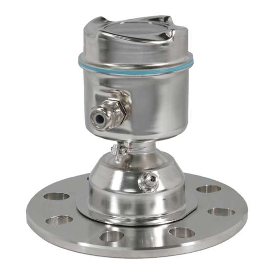
Description SITRANS LR560 overview SITRANS LR560 is a 2-wire, 78 GHz FMCW radar level transmitter for continuous monitoring of solids and liquids in vessels to a range of 100 m (329 ft). The plug-and-play performance is ideal for all solids applications, including those with extreme dust and high temperatures to +200 °C (+392 °F). - Page 23 Description 3.1 SITRANS LR560 overview LR560 (FOUNDATION FIELDBUS) Operating Instructions, 06/2018, A5E34648692-AE...
-
Page 24: Installing/Mounting
Refer to the information in Technical data (Page 171). Note Material compatibility Siemens can provide you with support concerning selection of sensor components wetted by process media. However, you are responsible for the selection of components. Siemens accepts no liability for faults or failures resulting from incompatible materials. -
Page 25: Installation Location Requirements
Installing/mounting 4.1 Basic safety instructions WARNING Exceeded maximum permissible operating pressure Risk of injury or poisoning. The maximum permissible operating pressure depends on the device version, pressure limit and temperature rating. The device can be damaged if the operating pressure is exceeded. -
Page 26: Proper Mounting
Installing/mounting 4.1 Basic safety instructions CAUTION Direct sunlight Device damage. The device can overheat or materials become brittle due to UV exposure. • Protect the device from direct sunlight. • Make sure that the maximum permissible ambient temperature is not exceeded. Refer to the information in Technical data (Page 171). -
Page 27: Installation Instructions
Pressure equipment directive (PED, 2014/68/EU) Note Pressure-rated version only • SITRANS LR560 units are pressure tested, meeting or exceeding the requirements of the ASME Boiler and Pressure Vessel Code and the European Pressure Equipment Directive. • The serial numbers stamped in each process connection body provide a unique identification number indicating date of manufacture. -
Page 28: Nozzle Location
Installing/mounting 4.2 Installation instructions 4.2.2 Nozzle location Note False echoes For details on avoiding false echoes, see AUTO ECHO SUPPRESSION (2.4.8.1.) (Page 132). ● Avoid central locations on tall, narrow vessels Beam angle ● Beam angle is the width of the cone where the energy density is half of the peak energy density. -
Page 29: Sunshield
Installing/mounting 4.2 Installation instructions ① ambient temperature: –40 °C to +80 °C (–40 °F to +176 °F) ② process temperature: –40 to +100 °C (–40 to +212 °F) or –40 to +200 °C (–40 to +392 °F) depending on the version 4.2.4 Sunshield The LR560 display can be protected by an optional sun shield if the instrument will be... -
Page 30: Aimer Adjustment
C spanner, until the LR560 drops down slightly. The enclosure can then be turned freely. 2. Direct SITRANS LR560 so the antenna is pointed at an angle perpendicular to the material surface, if possible. 3. When the desired position is reached, re-tighten the locking ring using the C spanner, and tighten set screws. -
Page 31: Air Purging System
• It is the customer’s responsibility to ensure that any vacuum or pressure in the measured vessel is maintained, considering the hole that passes through the process connection and SITRANS LR560 antenna system. Air Consumption (flow rate versus applied pressure) Air pressure (psi) Approx. -
Page 32: Removable Display
The optional display can be rotated as required, to one of 4 positions, 90 degrees apart, see Connecting SITRANS LR560 (Page 36). It can also be used to transfer parameters from one device to another, see COPY PARAMETERS FROM DISPLAY (1.4) (Page 119). -
Page 33: Disassembly
Installing/mounting 4.3 Disassembly Disassembly 4.3.1 Incorrect disassembly WARNING Incorrect disassembly The following risks may result from incorrect disassembly: - Injury through electric shock - Risk through emerging media when connected to the process - Risk of explosion in hazardous area In order to disassemble correctly, observe the following: •... -
Page 34: Connecting
Connecting Basic safety information WARNING Unsuitable cables, cable glands and/or plugs Risk of explosion in hazardous areas. • Use only cable glands/plugs that comply with the requirements for the relevant type of protection. • Tighten the cable glands in accordance with the torques specified in Technical data (Page 171). -
Page 35: Incorrect Connection To Power Source
Connecting 5.1 Basic safety information WARNING Missing PE/ground connection Risk of electric shock. Depending on the device version, connect the power supply as follows: • Power plug: Ensure that the used socket has a PE/ground conductor connection. Check that the PE/ground conductor connection of the socket and power plug match each other. - Page 36 Connecting 5.1 Basic safety information WARNING Incorrect selection of type of protection Risk of explosion in areas subject to explosion hazard. This device is approved for several types of protection. 1. Decide in favor of one type of protection. 2. Connect the device in accordance with the selected type of protection. 3.
-
Page 37: Connecting Sitrans Lr560
Connecting 5.2 Connecting SITRANS LR560 Connecting SITRANS LR560 Note • Check the device label on your instrument, to verify the approval rating. • Use appropriate conduit seals to maintain IP or NEMA rating. • Use twisted pair cable: AWG 22 to 14 (0.34 mm² to 2.5 mm²). -
Page 38: Configuration Diagrams
Connecting 5.3 Configuration diagrams Configuration diagrams 5.3.1 Basic configurations 5.3.1.1 Configuration via PCI/PCMCIA card ① ③ ⑤ PCI/PCMCIA bus H1 Interface FC375 ② ④ ⑥ NI-FBUS Configurator FF (H1) LR560 FF PC/laptop 5.3.1.2 Configuration via linking device ① ④ ⑥ controller HSE/H1 Linking Device FC375... -
Page 39: Hazardous Area Configurations
Connecting 5.3 Configuration diagrams 5.3.2 Hazardous area configurations 5.3.2.1 Configuration via PCI/PCMCIA card ① ④ ⑦ Non-hazardous area PCI/PCMCIA bus FF (H1) ② ⑤ ⑧ Hazardous area NI-FBUS configurator PC/laptop LR560 FF ③ ⑥ FC375 H1 interface 5.3.2.2 Configuration via Gateway and linking device ①... -
Page 40: Nameplates For Hazardous Area Installations
FM/CSA Class 1, Div 2 installation and connection drawing The FM/CSA Class 1, Div 2 connection drawing (A5E02795836) listed on the device nameplate can be downloaded from the Siemens Industry Image Database: FM/CSA Class 1, Div 2 connection drawing (http://www.automation.siemens.com/bilddb/index.aspx?gridview=view2&objkey=G_FI01_XX _05528&showdetail=true&view=Search) -
Page 41: Instructions Specific To Hazardous Area Installations
Connecting 5.5 Instructions specific to hazardous area installations Instructions specific to hazardous area installations 5.5.1 (Reference European ATEX Directive 2014/34/EU, Annex II, 1.0.6) The following instructions apply to equipment covered by certificate number SIRA 09ATEX9356X and Sira 09ATEX4357X. 1. For use and assembly and details of marking/coding, refer to the main instructions. 2. -
Page 42: Commissioning
Commissioning Basic safety notes WARNING Improper commissioning in hazardous areas Device failure or risk of explosion in hazardous areas. • Do not commission the device until it has been mounted completely and connected in accordance with the information in Installing/mounting (Page 23). •... - Page 43 Commissioning 6.2 Activating the radar device WARNING Hazardous contact voltage Risk of injury through hazardous contact voltage when the device is open or not completely closed. The degree of protection specified on the nameplate or in Technical data (Page 171) is no longer guaranteed if the device is open or not properly closed.
-
Page 44: Activating The Radar Device
6.2 Activating the radar device Activating the radar device Power up the instrument. A transition screen showing first the Siemens logo and then the current firmware revision is displayed while the first measurement is being processed. The first time the device is configured, you will be prompted to select a language (English, German, French, Spanish or Chinese). - Page 45 Commissioning 6.3 The LCD display PROGRAM mode display Navigation view ● A visible menu bar indicates the menu list is too long to display all items. ● The depth of the item band on the menu bar indicates the length of the menu list: a deeper band indicates fewer items.
-
Page 46: Commissioning Via Local Display
6.4.1 Local operation SITRANS LR560 carries out its level measurement tasks according to settings made via parameters. The settings can be modified locally via the optional local graphical display which consists of an LCD display with buttons. You can use either the push buttons or an infrared handheld programmer to make changes. -
Page 47: Commissioning Via Handheld Programmer
Commissioning 6.5 Commissioning via handheld programmer To add or delete digits using the push buttons: When the enter icon is lit, press UP to insert a digit on the right, DOWN delete the right-most digit, RIGHT to accept the value, or LEFT to cancel. -
Page 48: Hand Programmer_Note
Commissioning 6.5 Commissioning via handheld programmer 6.5.2 Hand programmer_note The handheld programmer used with this device contains lithium batteries that are non- replaceable. 6.5.3 Lithium batteries Lithium batteries are primary power sources with high energy content designed to provide the highest possible degree of safety. WARNING Potential hazard Lithium batteries may present a potential hazard if they are abused electrically or... -
Page 49: Key Functions In Measurement Mode
Commissioning 6.5 Commissioning via handheld programmer 6.5.4 Key functions in measurement mode Key functions in measurement mode Function Result Updates the loop New value is shown in secondary region of local display. current Updates internal enclosure tempera- ture reading Updates echo confi- New value is shown in secondary region of local display. -
Page 50: Programming
Commissioning 6.5 Commissioning via handheld programmer 6.5.5 Programming 6.5.5.1 Programming the radar device Note • While the device is in PROGRAM mode the output remains fixed and does not respond to changes in the device. • The device automatically returns to Measurement mode after a period of inactivity in PROGRAM mode (between 15 seconds and 2 minutes, depending on the menu level). -
Page 51: Parameter Menus
Commissioning 6.5 Commissioning via handheld programmer 6.5.5.3 Parameter menus 1. Enter PROGRAM Using local display buttons: mode Press RIGHT • Using handheld programmer: 1. Point the programmer at the display from a maximum distance of 300 mm (1 ft). 2. RIGHT activates PROGRAM mode and opens menu level 1. - Page 52 Commissioning 6.5 Commissioning via handheld programmer Key functions in Navigation mode Name Menu level Function UP or DOWN arrow menu or parameter Scroll to previous or next menu or pa- rameter. RIGHT arrow menu Go to first parameter in the selected menu, or open next menu.
- Page 53 Commissioning 6.5 Commissioning via handheld programmer Key functions in Program mode Name Function UP or DOWN Selecting options Scrolls to item. arrow Alphanumeric Increments or decrements digits • editing Toggles plus and minus sign • RIGHT arrow Selecting options • Accepts the data (writes the parameter) Changes from Edit to Navigation mode •...
-
Page 54: Quick Start Wizard Via The Handheld Programmer
Commissioning 6.5 Commissioning via handheld programmer 6.5.5.4 Quick Start Wizard via the handheld programmer Note • A reset to factory defaults should be performed before running the Quick Start Wizard if the device has been used in a previous application. See Quick Start Wizard via the local display push buttons (Page 45). - Page 55 Commissioning 6.5 Commissioning via handheld programmer Vessel Factory setting: STEEL Setting range: STEEL or CONCRETE Purpose: Select vessel construction material. Description: Selecting either STEEL or CONCRETE does a functional reset; see • MASTER RESET (4.1.) (Page 145). Selecting STEEL changes the setting for POSITION DETECT (2.4.5.2.) •...
- Page 56 Commissioning 6.5 Commissioning via handheld programmer Units Factory setting: Setting range: m, cm, mm, ft, in Purpose: Sensor measurement units. Parameter view Edit mode Operation Factory setting: LEVEL Setting range: LEVEL Distance to material surface referenced from Low calibration point SPACE Distance to material surface referenced from High calibration point...
- Page 57 Commissioning 6.5 Commissioning via handheld programmer Low calibration point Factory setting: 40.000 m or 100.000 m Setting range: 0.000 to 40.000 m or 0.000 to 100.000 m Purpose: Distance from Sensor Reference to Low Calibration Point: usually process empty level. See Dimension drawings (Page 177) for an illustration. Parameter view Edit mode High calibration point...
-
Page 58: Requesting An Echo Profile
Commissioning 6.5 Commissioning via handheld programmer 6.5.5.5 Requesting an Echo Profile 1. Enter Navigate to: Level Meter > Diagnostics (3.) > Echo profile (3.1.). PROGRAM mode Press RIGHT to request a profile. ① ② Confidence ③ Distance from Low Calibration Point to vertical cross-hair ④... -
Page 59: Device Address
Commissioning 6.6 Device Address Device Address Note The address can only be changed from a remote master such as NI-FBUS Configurator or Foundation Fieldbus for Level DeltaV. For further details see Addressing in the manual, instruments (7ML19985MP01) Read only. The unique address of the device on the network. 1. - Page 60 Commissioning 6.7 Application example Quick Start Parameter Setting Description Vessel STEEL Selects vessel construction material. Response Rate SLOW Resets fill rate and empty rate to 0.1 m/minute. Units Sensor measurement units. Operation LEVEL Material level referenced from low calibration point Low Calibration Point 15.5 Process empty level.
- Page 61 Commissioning 6.7 Application example LR560 (FOUNDATION FIELDBUS) Operating Instructions, 06/2018, A5E34648692-AE...
-
Page 62: Operating
Operating Remote operation 7.1.1 Operating via AMS Device Manager 7.1.1.1 Functions in AMS Device Manager Functions in AMS Device Manager AMS Device Manager monitors the process values, alarms and status signals of the device. It allows you to display, compare, adjust, verify, and simulate process device data. Device configuration and monitoring is performed via parameters organized into three function groups: ●... - Page 63 Operating 7.1 Remote operation ① active parameter tab ② parameter dialog window ③ button access to function groups ④ active function block (LTB) ⑤ active function group (highlighted) Key Features of AMS Device Manager version 9.0. Note • For details on using the features below, see the page listed. •...
-
Page 64: Programming Via Ams Device Manager
Operating 7.1 Remote operation Block location of features Feature Function Group Block Quick Start Wizard steps (Page 67) Configure/setup RESOURCE Echo profile (Page 81) TVT (Page 78) Maintenance & Diagnostics (LTB) (Page 81) Maintenance & Diagnostics (RESOURCE) (Page 92) RESOURCE Security (RESOURCE) (Page 94) RESOURCE Alarms &... -
Page 65: Adding A New Device
SITRANS LR560 requires the EDD for AMS Device Manager version 9.0. Check the product page of our website (www.siemens.com/LR560), under Support > SoftwareDownloads, for the latest version of EDD: SITRANS LR560 FF - Foundation Fieldbus - AMS V9.0. 1. Check that you have the latest version of the EDD for AMS Device Manager that matches the firmware revision of your device. - Page 66 Operating 7.1 Remote operation Note The Device Tag described above is distinct from the Tag that describes each block type Identification (located in the folder of each block). Startup 1. Launch AMS Device Manager 1. Launch AMS Device Manager– AMS Device Manager. 2.
- Page 67 Operating 7.1 Remote operation 1. Navigate to Configure/Setup > Resource Block > Operation and click Methods to open the dialog window. 2. In the General field, click Master Reset then click Next to perform a reset to factory defaults. Click Next to accept the default reset to Factory Defaults. ①...
-
Page 68: Configuring A New Device
Operating 7.1 Remote operation 7.1.1.4 Configuring a new device Note • The LR560 FF is shipped with RESOURCE and LTB blocks in Out of Service mode. • If you complete the Quick Start Wizard via local operation the first time it is used, it will automatically put the RESOURCE and LTB blocks into AUTO mode. - Page 69 Operating 7.1 Remote operation Step 1 – Identification Click Step 1 - Identification. If you wish to accept the default values, go directly to Step 2 (Descriptor, Message, and Date fields can be left blank). Or if desired, make changes then click Apply. LR560 (FOUNDATION FIELDBUS) Operating Instructions, 06/2018, A5E34648692-AE...
- Page 70 Operating 7.1 Remote operation Step 2 – Application Note • Selecting either STEEL or CONCRETE does a functional reset, see MASTER RESET (4.1.) (Page 145). • Selecting STEEL changes the setting for POSITION DETECT (2.4.5.2.) (Page 129) to Rising Edge. and for ALGORITHM (2.4.5.1.) (Page 128) to F. •...
- Page 71 Operating 7.1 Remote operation Step 3 – Ranges Note Selecting SLOW Response Rate changes setting for AVERAGE AMOUNT (2.8.3.) (Page 141) to 0.9. Click Step 3 - Ranges. If you wish to accept the default values, go directly to step 4. Or make changes as desired, then click Apply.
-
Page 72: Changing Block Modes
Operating 7.1 Remote operation Step 4 – Summary Click Step 4 - Summary. Check parameter settings. Return to individual steps if further changes are necessary. The Quick Start is now complete. Put Resource Block into Automatic Mode, see Changing block modes (Page 71). 7.1.1.5 Changing block modes Note... - Page 73 Operating 7.1 Remote operation To change Resource Block mode: 1. Navigate to Configure/Setup > Resource Block > Operation > Block Mode and click Block Mode to open the dialog window. 2. Select the desired Target mode and deselect the other option. Click Apply (the Apply button is activated when a change is made).
-
Page 74: Configure/Setup Parameters
Operating 7.1 Remote operation 7.1.1.6 Configure/Setup parameters Transducer Block parameters Identification and Operation are common to all three Transducer Blocks: Level Transducer Block, LCD Transducer Block, and Diagnostic Transducer Block. Identification (LTB, LCD, DIAG) Navigate to Configure/Setup > LTB and click Identification to open the dialog window for access to: Identification: ●... - Page 75 Operating 7.1 Remote operation Operation (LTB, LCD, DIAG) Navigate to Configure/Setup > LTB > Operation and click Block Modes to open the dialog window for access to block modes: 1. Actual Mode (read only) This is the current mode of the block, which may differ from the target based on operating conditions.
- Page 76 Operating 7.1 Remote operation Simulation (Input) Note • To activate simulation via AMS Device Manager or the 375 Field Communicator, simulation must also be set to Enabled on the device. See SIMULATE ENABLE (4.12.) (Page 155). • Before enabling or disabling Simulation, put LTB Block into OOS mode (see Changing block modes (Page 71)).
- Page 77 Operating 7.1 Remote operation Setup (LTB) Note See AMS menu structure (Page 105) and for parameters followed by a reference number, more detailed descriptions can be found in Parameter Reference (Page 117). Sensor (LTB) Navigate to Configure/Setup > LTB > Setup and click Sensor for access to: General ●...
- Page 78 Operating 7.1 Remote operation Rate Note Selecting SLOW Response Rate changes setting for AVERAGE AMOUNT (2.8.3.) (Page 141) to 0.9. ● Response Rate ● Fill Rate per Minute ● Empty Rate per Minute Signal Processing (LTB) Note See AMS menu structure (Page 105) and for parameters followed by a reference number, more detailed descriptions can be found in Parameter Reference (Page 117).
- Page 79 Operating 7.1 Remote operation General Navigate to Configure/Setup > LTB > Setup > Signal Processing and click on General for access to: Range ● Near Range ● Far Range ● Minimum Sensor Value ● Maximum Sensor Value Echo Select ● Algorithm ●...
- Page 80 Operating 7.1 Remote operation Note • We recommend using the Auto False Echo Suppression Wizard. See AFES WIZARD (1.2.) (Page 118). • Put LTB Block into OOS Mode before changing settings, then back into AUTO mode to display TVT. TVT (Auto False Echo Suppression) Navigate to Configure/Setup >...
- Page 81 Operating 7.1 Remote operation TVT Shaper 1 ● Shaper breakpoints 1 to 40 TVT Shaper 2 ● Shaper breakpoints 41 to 80 TVT Shaper 3 ● Shaper breakpoints 81 to 120 Manual TVT curve Note Put LTB Block into OOS Mode before changing settings, then back into AUTO mode to display TVT.
- Page 82 Operating 7.1 Remote operation Echo profile ① Time field Navigate to Configure/Setup > LTB > Setup > Signal Processing > Echo Profile to view the current echo profile and to access Echo Profile Parameters (view only). Echo Profile Parameters (view only) ●...
- Page 83 Operating 7.1 Remote operation Remaining Sensor Lifetime Navigate to Configure/Setup > LTB > Maintenance and Diagnostics > Remaining Sensor Lifetime. Sensor Lifetime Click Sensor Lifetime tab for access to: ● Lifetime (Expected) ● Time in Operation ● Remaining Lifetime ● Activation of Reminders ●...
- Page 84 Operating 7.1 Remote operation Service Schedule Navigate to Configure/Setup > LTB > Maintenance and Diagnostics > Service Schedule. Service Schedule Click Service Schedule tab for access to ● Service Interval ● Time Since Last Service ● Time Until Next Service ●...
- Page 85 Operating 7.1 Remote operation Electronics Temperature ● Electronics Temperature Displays the current internal temperature of the device ● Minimum Value ● Maximum Value Communication (LTB) Navigate to Configure/Setup > LTB > Communication for access to: Communication: ● Static Revision No., see STATIC REVISION NO. (2.5.1.) (Page 136) LR560 (FOUNDATION FIELDBUS) Operating Instructions, 06/2018, A5E34648692-AE...
- Page 86 Operating 7.1 Remote operation Configure/Setup (LCD Block) Identification (LCD) See Identification (LTB, LCD, DIAG) (Page 73). Operation (LCD) See Operation (LTB, LCD, DIAG) (Page 74). Block Modes Navigate to Configure/Setup > LCD > Operation and click Block Modes to open the dialog window for access to: (read only) ●...
- Page 87 Operating 7.1 Remote operation Local Display ● Language ● LCD Contrast ● LCD Backlight Local Display (continued) ● Local Operation If local operation is disabled remotely and no communication activity exists for 30 seconds, the parameter is made visible again locally. Communication (LCD) Navigate to Configure/Setup >...
- Page 88 Operating 7.1 Remote operation Communication: ● Static Revision no., see STATIC REVISION NO. (2.5.1.) (Page 136) Configure/Setup (Diagnostic Transducer Block-DIAG) Configure/Setup (Diagnostic Transducer Block-DIAG) Note Parameters in the Diagnostic Transducer Block used solely by factory personnel. Identification (DIAG) Navigate to Configure/Setup > DIAG > Identification. Identification, see Identification (LTB, LCD, DIAG) (Page 73).
- Page 89 Operating 7.1 Remote operation Configure/Setup (Resource Block-RESOURCE) Note • For a complete list of parameters accessible via AMS, see AMS menu structure (Page 105). • For parameters followed by a reference number, additional information is available in Parameter Reference (Page 117). Identification (RESOURCE) Navigate to Configure/Setup >...
- Page 90 Operating 7.1 Remote operation (read only) Device ● Manufacturer ● Product Name The manufacturer's product name for this device. ● Order Number The manufacturer's order number (MLFB) for this device. ● Range Mode Measuring range of the device. ● Serial Number The manufacturer's unique serial number for this device.
- Page 91 Operating 7.1 Remote operation Block Modes Note If the RESOURCE block is set to Out of Service, the LTB, and AIFB blocks are forced to Out of Service also, but the LCD and DIAG blocks remain in Automatic mode. ● Actual Mode ●...
- Page 92 Operating 7.1 Remote operation ① Master Reset 1. Click the Master Reset button, then click Next to perform a reset. 2. Select the Reset Type: Reset Type Result Factory Defaults Default. Resets all user parameters to the manufacturer's default settings. Following this type of reset, complete reprogramming is required.
- Page 93 Operating 7.1 Remote operation Maintenance & Diagnostics (RESOURCE) Navigate to Configure/Setup > RESOURCE > Maintenance & Diagnostics for access to: Remaining Device Lifetime ● Lifetime (Expected) (read only) ● Remaining Lifetime (read only) ● Time in Operation ● Activation of Reminders ●...
- Page 94 Operating 7.1 Remote operation Click on Calibration Performed to reset Time Since Last Calibration to 0 hours. Click Apply to accept the change. Wear (read only) ● Powered Days (read only) ● Power-on resets LR560 (FOUNDATION FIELDBUS) Operating Instructions, 06/2018, A5E34648692-AE...
- Page 95 Operating 7.1 Remote operation Communication (RESOURCE) Navigate to Configure/Setup > RESOURCE > Communication to read the following: ● Manufacturer ● Device Type Manufacturer's model number associated with the device ● Device Revision ● DD Revision Revision of the DD (also called EDD) associated with this device. ●...
- Page 96 Operating 7.1 Remote operation Device diagnostics (Level Transducer Block-LBT) Note For explanations of the alarms and errors listed below, see Parameter Description charts for Foundation Fieldbus for Level instruments the respective block in the manual (7ML19985MP01) Alarms & Errors (LTB) Navigate to Device Diagnostics >...
- Page 97 Operating 7.1 Remote operation Block Error Click on Block Error to open the dialog window to read the following: Failures ● Input Failure ● Output Failure ● Memory Failure ● Lost Static Data ● Lost Non-Volatile Data ● Readback Check ●...
- Page 98 Operating 7.1 Remote operation 1. From the Block Error tab, check the Maintenance window to display the level of maintenance alarm that is active. 2. From the Block Alarm tab, check the Alarm State window to display the level of maintenance alarm that has been acknowledged.
- Page 99 Operating 7.1 Remote operation Extended Diagnostics (LTB) Navigate to Device Diagnostics > LTB > Extended Diagnostics to read the following: Detailed Error Info ● Loss of Echo ● No Tech Power ● Sensor Lifetime Reminder 1 ● Sensor Lifetime Reminder 2 ●...
- Page 100 Operating 7.1 Remote operation Block Error Click Block Error tab to read: Failures ● Input Failure ● Output Failure ● Memory Failure ● Lost Static Data ● Lost Non-Volatile Data ● Readback Check ● Device Fault State ● Block Configuration ●...
- Page 101 Operating 7.1 Remote operation Write Alarm Values available on Block Alarm tab are also available for Write Alarm with one exception: the Value parameter on the Write Alarm tab is a Discrete Value. Alarm Summary Click on Alarm Summary tab to open the dialog window to read: Current ●...
- Page 102 Operating 7.1 Remote operation Extended Diagnostics (RESOURCE) Navigate to Device Diagnostics > RESOURCE > Extended Diagnostics to read: Detailed Error Info • Device Lifetime Reminder 1 • External RAM • Device Lifetime Reminder 2 • Memory RAM • Calibration Schedule Reminder 1 •...
- Page 103 Operating 7.1 Remote operation For level applications, chart range is affected by High and Low Level Point values set in Configure/Setup > LTB > Setup > Sensor. Trend View Click Trend View tab to view: ● Trend Values ● Trend View The primary variable and the channel 1 output from the transducer block.
-
Page 104: Password Protection
Operating 7.1 Remote operation Echo Profile Click Echo Profile to read: Echo Profile Parameters ● Level Measurement ● Distance Measurement ● Confidence ● Near Range 7.1.1.7 Password protection Password Protection An AMS Device Manager administrator can configure the user to require a password. The use of passwords is recommended. - Page 105 Operating 7.1 Remote operation To configure a new user/edit existing user: 1. From the Windows taskbar select: Start > AMS Device Manager > User Manager. 2. In the User Manager window click on Add User. The Add User Wizard dialog allows you to: –...
-
Page 106: Ams Menu Structure
Operating 7.1 Remote operation 7.1.1.8 AMS menu structure Note Where a parameter number is listed, more information is available for that parameter in Parameter Reference (Page 117). Configure/Setup Function Parameter number Group Level Transducer Block Identification Identification Identification (tab) Descriptor 2.1.2. - Page 107 Operating 7.1 Remote operation Calibration 2.3.5. (Page 123) Low Cal. Point 2.3.5.1. (Page 123) High Cal. Point 2.3.5.2. (Page 123) Sensor Offset 2.3.5.3. (Page 124) Low Level Point 2.3.5.4. (Page 124) High Level Point 2.3.5.5. (Page 124) Level Offset 2.3.5.6. (Page 124) Rate 2.3.6.
- Page 108 Operating 7.1 Remote operation Breakpoints 1-40 TVT Shaper 2 (tab) Breakpoints 41 - 80 Level Transducer Block (continued) TVT Shaper 3 (tab) Breakpoint s 81 -120 Manual TVT-Curve Manual TVT-Diagram (tab) Maintenance & Diagnostics Remaining Sensor Lifetime 4.3. (Page 148) Sensor Lifetime (tab) Lifetime (Expected) 4.3.1.
- Page 109 Operating 7.1 Remote operation Descriptor 2.1.2. (Page 121) Transducer Block Type Strategy Plant Unit Operation Block Modes Block Modes (tab) Actual Mode Target Mode Permitted Mode Normal Mode Setup Local Display Local Display (tab) Language 7. (Page 157) LCD Contrast 4.10.
- Page 110 Operating 7.1 Remote operation Resource Block Identification Identification Identification (tab) Identification Descriptor 2.1.2. (Page 121) Message 2.1.3. (Page 121) Date 2.1.4. (Page 121) Strategy Plant Unit Device Manufacturer 5.3. (Page 156) Product Name Order Number Range Mode Serial Number Hardware Revision 2.2.1.
- Page 111 Operating 7.1 Remote operation Lifetime (Expected) 4.2.1. (Page 146) Remaining Lifetime 4.2.3. (Page 146) Time in Operation 4.2.2. (Page 146) Activation of Reminders 4.2.4. (Page 147) Reminder 1 before Lifetime (Required) 4.2.5. (Page 147) Reminder 2 before Lifetime (Demand- 4.2.6. (Page 147) Calibration Schedule 4.5.
- Page 112 Operating 7.1 Remote operation Failures Input Failure Output Failure Memory Failure Lost Static Data Lost Non-Volatile Data Readback Check Device Fault State Block Configuration Link Configuration Other Maintenance Maintenance Required Maintenance Demanded Information Simulation Active Local Override Power Up Out Of Service XD Error Transducer Error Block Alarm...
- Page 113 Operating 7.1 Remote operation Internal Temp High Internal Temperature Calibration Velocity Calibration Transducer Temperature Sensor Transducer Temperature High Transducer Temperature Low LCD Transducer Block Alarms & Errors Block Error Block Error (tab) Failures Input Failure Output Failure Memory Failure Lost Static Data Lost Non-Volatile Data Readback Check Device Fault State...
- Page 114 Operating 7.1 Remote operation Block Error Block Error (tab) Failures Input Failure Output Failure Memory Failure Lost Static Data Lost Non-Volatile Data Readback Check Device Fault State Block Configuration Link Configuration Other Maintenance Maintenance Required Maintenance Demanded Information Simulation Active Local Override Power Up Out Of Service...
- Page 115 Operating 7.1 Remote operation Readback Check Device Fault State Block Configuration Link Configuration Other Maintenance Maintenance Required Maintenance Demanded Information Simulation Active Local Override Power Up Out Of Service Block Alarm Block Alarm (tab) Unacknowledged Alarm State Subcode Value Write Alarm Write Alarm (tab) Unacknowledged Alarm State...
- Page 116 Operating 7.1 Remote operation Extended diagnostics Extended Diagnostics Extended Diagnostics (tab) Detailed Error Info Device Lifetime Reminder 1 Device Lifetime Reminder 2 Calibration Schedule Reminder 1 Service Schedule Reminder 2 Internal Error External RAM Memory RAM Memory EEPROM Memory EEPROM Flags Memory Flash Invalid Loader Process Variables Function Group...
- Page 117 Operating 7.1 Remote operation LR560 (FOUNDATION FIELDBUS) Operating Instructions, 06/2018, A5E34648692-AE...
-
Page 118: Parameter Reference
Parameter Reference Note • Most parameters are common to both local and remote operation, and are listed below. For a complete list of AMS parameters, see AMS menu structure (Page 105). • To enter Program mode using the device buttons, press RIGHT . -
Page 119: Afes Wizard (1.2.)
If you have a vessel with known obstructions, we recommend using AFES to prevent false echo detection. This feature can also be used if SITRANS LR560 displays a false high level, or the reading is fluctuating between the correct level and a false high level. -
Page 120: Copy Parameters To Display (1.3.)
8.1 QUICK START (1.) 8.1.3 COPY PARAMETERS TO DISPLAY (1.3.) Transfers parameter settings from a device to the local display interface. See Connecting SITRANS LR560 (Page 36) for instructions on removing the local display interface. 1. Press RIGHT to edit. -
Page 121: Copy Firmware To Display (1.5.)
Parameter Reference 8.2 SETUP (2.) 8.1.5 COPY FIRMWARE TO DISPLAY (1.5.) Transfers firmware from a device to the local display interface. 1. Press RIGHT to edit. 2. Press DOWN to select Start and RIGHT to begin the transfer. SW UPLOAD is displayed, then the device returns to Measurement mode. 8.1.6 COPY FIRMWARE FROM DISPLAY (1.6.) Note... -
Page 122: Identification (2.1.)
Parameter Reference 8.2 SETUP (2.) 8.2.1 IDENTIFICATION (2.1.) 8.2.1.1 TAG (2.1.1.) Text that can be used in any way. A recommended use is as a unique label for a field device in a plant. Limited to 8 ASCII characters. Read only on device, Read/Write using SIMATIC PDM and AMS. -
Page 123: Sensor (2.3.)
Parameter Reference 8.2 SETUP (2.) 8.2.3 SENSOR (2.3.) 8.2.3.1 UNIT (2.3.1.) Factory setting: Setting range: m, cm, mm, ft, in, % Purpose: PV (Primary Value) and SV (Secondary Sensor measurement units). Used in setting High/Low Calibration Point, and displayed on LCD and in PDM. Description: Changing units to % will update the mA setpoints. -
Page 124: Loe Timer (2.3.4.)
Parameter Reference 8.2 SETUP (2.) 8.2.3.4 LOE TIMER (2.3.4.) Note When a loss of echo occurs, Loss of Echo (LOE) (Page 196) determines the material level to be reported when the fail-safe timer expires. Factory setting: 100 s Setting range: 0.00 to 7200 seconds Purpose: Sets the reaction speed of the device to measurement changes. - Page 125 Parameter Reference 8.2 SETUP (2.) SENSOR OFFSET (2.3.5.3.) Factory setting: 0.00 m Setting range: -100 to 100 m Purpose: A constant offset that can be added to or subtracted from the sensor value to compensate for a shifted sensor reference point. For example, when adding a thicker gasket or reducing the standoff/nozzle height.
-
Page 126: Rate (2.3.6.)
Parameter Reference 8.2 SETUP (2.) 8.2.3.6 RATE (2.3.6.) RESPONSE RATE (2.3.6.1.) Changing Response Rate resets FILL RATE/MIN (2.3.6.2.) (Page 126) EMPTY RATE/MIN (2.3.6.3.) (Page 126) AVERAGE AMOUNT (2.8.3.) (Page 141) Factory setting: Medium Setting range: Response FILL RATE/MIN (2.3.6.2.) FILTER TIME AVERAGE rate (Page... - Page 127 Defines the maximum rate at which the reported sensor value is allowed to increase. Allows you to adjust the SITRANS LR560 response to increas- es in the actual material level. Fill Rate is automatically updated whenever Response Rate is altered.
-
Page 128: Signal Processing (2.4.)
Parameter Reference 8.2 SETUP (2.) Note The selected rate will also impact the AVERAGE AMOUNT (2.8.3.) (Page 141) parameter. For example, a SLOW setting will change it to 0.9, and a FAST setting may require it to be reduced to a very low value. 8.2.4 SIGNAL PROCESSING (2.4.) 8.2.4.1... -
Page 129: Minimum Sensor Value (2.4.3.)
Parameter Reference 8.2 SETUP (2.) 8.2.4.3 MINIMUM SENSOR VALUE (2.4.3.) Read only. Defines the minimum usable value for the measuring range, in units defined in . (Default = 0.0 m) UNIT (2.3.1.) (Page 122) For access via AMS Device Manager see Range under Signal Processing (LTB) (Page 77). ①... - Page 130 Parameter Reference 8.2 SETUP (2.) Best of First and Largest echo Best Largest Echo Best First Echo LAST Last True First Echo Purpose: Selects the algorithm to be applied to the echo profile to extract the true echo. POSITION DETECT (2.4.5.2.) Note Vessel type Selecting Steel or Concrete vessel type in the Quick Start wizard changes the setting for...
-
Page 131: Sampling (2.4.6.)
Parameter Reference 8.2 SETUP (2.) CLEF RANGE (2.4.5.4.) Note CLEF range • CLEF Range is referenced from Far Range. • The value for CLEF Range must include the difference between Far Range and Low Calibration Point, plus any level above the Low Calibration Point to be managed by the CLEF algorithm. -
Page 132: Echo Lock (2.4.6.1.)
Parameter Reference 8.2 SETUP (2.) 8.2.4.7 ECHO LOCK (2.4.6.1.) Factory setting: Material Agitator Setting range: Lock Off Maximum Verification (not recommended for radar) Material Agitator Total Lock (not recommended for radar) Purpose: Selects the measurement verification process. Related parameters: FILL RATE/MIN (2.3.6.2.) (Page 126) EMPTY RATE/MIN (2.3.6.3.) (Page 126) UP SAMPLING (2.4.6.2.) (Page 131) DOWN SAMPLING (2.4.6.3.) (Page 131) -
Page 133: Echo Quality (2.4.7.)
Parameter Reference 8.2 SETUP (2.) Note Values in Echo Lock window The Echo Lock window is stored as a standard sample, but displayed in sensor units. Any value entered for the Echo Lock window will be rounded to the nearest sample. 8.2.4.11 ECHO QUALITY (2.4.7.) CONFIDENCE (2.4.7.1.) - Page 134 Parameter Reference 8.2 SETUP (2.) Before Auto False Echo Suppression ① TVT Hover Level ② false echo ③ material level ④ default TVT ⑤ echo marker After Auto False Echo Suppression ① learned TVT ② Auto False Echo Suppression Range ③...
-
Page 135: Auto Suppression Range (2.4.8.2.)
Parameter Reference 8.2 SETUP (2.) 8.2.4.14 AUTO SUPPRESSION RANGE (2.4.8.2.) Factory setting: 1.00 m Setting range: 0.00 to 45.00 m (or 105.00 m depending on model) Purpose: Defines the endpoint of the Learned TVT distance. Units are defined in UNIT (2.3.1.) (Page 122). Description: Used in combination with AUTO ECHO SUPPRESSION (2.4.8.1.) (Page 132). -
Page 136: Tvt Shaper (2.4.9.)
Parameter Reference 8.2 SETUP (2.) 8.2.4.17 TVT SHAPER (2.4.9.) Note • SHAPER MODE (2.4.8.4.) (Page 134) must be turned ON in order for TVT shaper breakpoints to be transferred • We recommend using AMS Device Manager to access this feature. •... -
Page 137: Aifb1 (2.5.)
Ensure that Mode is returned to AUTO when simulation or maintenance are completed.. Used to request an operating mode from the Analog Input Function Block. It allows you to put SITRANS LR560 into Manual mode (used in conjunction with Simulation) or Out-of- Service mode for maintenance purposes. -
Page 138: Input Scaling (2.5.4)
Parameter Reference 8.2 SETUP (2.) ① ② Sensor reference point High calibration point (process full level) ③ ④ Distance (SV2) Level (SV1) ⑤ Low calibration point (process empty level) 8.2.5.4 INPUT SCALING (2.5.4) Input scaling should match the XD_scale from the Level Transducer Block. See the manual Foundation Fieldbus for Level instruments (7ML19985MP01) for more detail. -
Page 139: Output Scaling (2.5.5.)
Parameter Reference 8.2 SETUP (2.) UNIT (2.5.4.3.) Engineering unit to be displayed with the output value. Options m, cm, mm, ft, in, %, Not Used, Unknown, Special DECIMAL POINT (2.5.4.4.) Read only. The number of digits to display after the decimal point (fixed to one). 8.2.5.5 OUTPUT SCALING (2.5.5.) Scales the Process Variable. -
Page 140: Hi Limit Alarm (2.5.6.1.)
Parameter Reference 8.2 SETUP (2.) UNIT (2.5.5.3.) Engineering unit to be displayed with the output value. Options m, cm, mm, ft, in, %, Not Used, Unknown, Special DECIMAL POINT (2.5.5.4.) Read only. The number of digits to display after the decimal point (fixed to one). 8.2.5.6 HI LIMIT ALARM (2.5.6.1.) Factory setting:... -
Page 141: Limit Hysteresis (2.5.6.5.)
Parameter Reference 8.2 SETUP (2.) 8.2.5.10 LIMIT HYSTERESIS (2.5.6.5.) Factory setting: 0.20 for 40 m version 0.50 for 100 m version Setting range: Range: 0 to 999999.00 Purpose: Hysteresis is used to adjust the sensitivity of the trigger for alarm messages. It is used to compensate when a process variable fluctuates around the same value as a limit. -
Page 142: Output No Offsets (2.7.3.)
Parameter Reference 8.2 SETUP (2.) 8.2.10 OUTPUT NO OFFSETS (2.7.3.) The value for Distance. 8.2.11 NARROW ECHO FILTER (2.8.1.) Factory setting: 0 = OFF Setting range: 0 to 255, greater = wider Purpose: Filters out echoes of a specific width. Description: To remove a false echo from the Echo Profile, take its width in mm and multiply it by 0.006. -
Page 143: Diagnostics (3.)
Parameter Reference 8.3 DIAGNOSTICS (3.) DIAGNOSTICS (3.) 8.3.1 ECHO PROFILE (3.1.) Note • LTB Block must be put back to AUTO mode to display Echo Profile. • Selected icon is highlighted. Allows you to request the current echo profile either via the handheld programmer, the local buttons, or via AMS Device Manager. -
Page 144: Fault Reset (3.2)
Parameter Reference 8.3 DIAGNOSTICS (3.) 8.3.2 FAULT RESET (3.2) Clears faults (see chart below). Clearing a fault in one parameter of a 'maintenance pair', automatically clears a fault in the second parameter of the pair. For example, entering S3 or S4 will clear a fault on Device (Maintenance Required), and on Device (Maintenance Demanded). -
Page 145: Maximum Value (3.4.2.)
Parameter Reference 8.3 DIAGNOSTICS (3.) 8.3.6 MAXIMUM VALUE (3.4.2.) The maximum recorded internal electronics temperature, reported in units defined in UNIT (2.3.1.) (Page 122) 8.3.7 PEAK VALUES (3.5.) 8.3.7.1 MINIMUM MEASURED VALUE (3.5.1.) The minimum recorded Sensor value, reported in units defined in UNIT (2.3.1.) (Page 122). 8.3.7.2 MAXIMUM MEASURED VALUE (3.5.2.) The maximum recorded Sensor value, reported in units defined in UNIT (2.3.1.) (Page 122). -
Page 146: Service (4.)
Parameter Reference 8.4 SERVICE (4.) SERVICE (4.) 8.4.1 MASTER RESET (4.1.) Note • The following parameters are not reset by any reset type: Write Protection, Auto False Echo Suppression Range, Learned TVT. • While an FF Object Dictionary Reset is in progress, the Master Reset Parameter View showing PREVIOUS/NEXT/BACK/EDIT options will be displayed. -
Page 147: Remaining Device Lifetime (4.2.)
Parameter Reference 8.4 SERVICE (4.) 8.4.2 REMAINING DEVICE LIFETIME (4.2.) Note • Default settings in the parameter tables are indicated with an asterisk (*) unless explicitly stated. • Four sets of parameters allow you to monitor the Device/Sensor Lifetimes and set up Maintenance/Service schedules, based on operating hours instead of a calendar-based schedule. -
Page 148: Reminder Activation (4.2.4.)
Parameter Reference 8.4 SERVICE (4.) 8.4.2.4 REMINDER ACTIVATION (4.2.4.) Allows you to enable a maintenance reminder. Options REMinder 1 (Maintenance REQuired) REMinder 2 (Maintenance DEManded) REMinders 1 AND 2 (Maintenance Required and Maintenance Demand- 1. First set the reminder values in REMINDER 1 (REQUIRED) (4.2.5.) (Page 147)/REMINDER 2 (DEMANDED) (4.2.6.) (Page 147). -
Page 149: Acknowledge (4.2.9.)
Parameter Reference 8.4 SERVICE (4.) 8.4.2.9 ACKNOWLEDGE (4.2.9.) Acknowledges the current maintenance reminder. To acknowledge an alert via the handheld programmer: 1. Press RIGHT twice to open parameter view and activate Edit Mode. 2. Press RIGHT to acknowledge the alert. 8.4.3 REMAINING SENSOR LIFETIME (4.3.) Note... -
Page 150: Reminder Activation (4.3.4.)
Parameter Reference 8.4 SERVICE (4.) 8.4.3.4 REMINDER ACTIVATION (4.3.4.) Allows you to enable a maintenance reminder. Options REMinder 1 (Maintenance REQuired) REMinder 2 (Maintenance DEManded) REMinders 1 AND 2 (Maintenance Required and Maintenance De- manded) 1. First set the limit values in REMINDER 1 (REQUIRED) (4.3.5.) (Page 149)/REMINDER 2 (DEMANDED) (4.3.6.) (Page 149). -
Page 151: Acknowledge (4.3.9.)
Parameter Reference 8.4 SERVICE (4.) 8.4.3.9 ACKNOWLEDGE (4.3.9.) Acknowledges the current maintenance reminder. To acknowledge an alert via the handheld programmer: 1. Press RIGHT twice to open parameter view and activate Edit Mode. 2. Press RIGHT to acknowledge the alert. 8.4.4 SERVICE SCHEDULE (4.4.) The device tracks service intervals based on operating hours and monitors the predicted... -
Page 152: Time Until Next Service (4.4.3.)
Parameter Reference 8.4 SERVICE (4.) 8.4.4.3 TIME UNTIL NEXT SERVICE (4.4.3.) Read only. SERVICE INTERVAL (4.4.1.) (Page 150) less TIME SINCE LAST SERVICE (4.4.2.) (Page 150). 8.4.4.4 REMINDER ACTIVATION (4.4.4.) Allows you to enable a maintenance reminder. Values TIMER OFF ON NO LIMITS ON REMinder 1 (Maintenance Required) checked ON REMinders 1 - 2 checked... -
Page 153: Acknowledge Status (4.4.8.)
Parameter Reference 8.4 SERVICE (4.) 8.4.4.8 ACKNOWLEDGE STATUS (4.4.8.) Indicates which level of maintenance reminder has been acknowledged. 8.4.4.9 ACKNOWLEDGE (4.4.9.) Acknowledges the current maintenance reminder. To acknowledge an alert via the handheld programmer: 1. Press RIGHT twice to open parameter view and activate Edit Mode. 2. -
Page 154: Time Until Next Calibration (4.5.3.)
Parameter Reference 8.4 SERVICE (4.) 8.4.5.3 TIME UNTIL NEXT CALIBRATION (4.5.3.) Read only. CALIBRATION INTERVAL (4.5.1.) (Page 152) less TIME SINCE LAST CALIBRATION (4.5.2.) (Page 152). 8.4.5.4 REMINDER ACTIVATION (4.5.4.) Allows you to enable a maintenance reminder. Values TIMER OFF ON NO LIMITS ON REMinder 1 (Maintenance Required) checked ON REMinders 1 - 2 checked... -
Page 155: Acknowledge Status (4.5.8.)
Parameter Reference 8.4 SERVICE (4.) 8.4.5.8 ACKNOWLEDGE STATUS (4.5.8.) Indicates which level of maintenance reminder has been acknowledged. 8.4.5.9 ACKNOWLEDGE (4.5.9.) Acknowledges the current maintenance reminder. To acknowledge an alert via the handheld programmer: 1. Press RIGHT twice to open parameter view and activate Edit Mode. 2. -
Page 156: Lcd Contrast (4.10.)
Parameter Reference 8.4 SERVICE (4.) 8.4.10 LCD CONTRAST (4.10.) Factory setting: Setting range: 0 to 20 Purpose: The factory setting is for optimum visibility at room temperature and in av- erage light conditions. Extremes of temperature will lessen the contrast. Description: Contrast setting will depend on ambient temperature. -
Page 157: Stored Software Version (4.14.)
8.5.3 MANUFACTURER (5.3.) Device manufacturer: Siemens. 8.5.4 DEVICE TYPE ID (5.4.) Hexadecimal integer defined by Siemens to uniquely identify each product with manufacturer's Id. (LR560 FF device= 00D7.) 8.5.5 DEVICE REVISION (5.5.) Manufacturer's revision number associated with this device. 8.5.6 ITK VERSION (5.6.) -
Page 158: Security (6.)
Parameter Reference 8.6 SECURITY (6.) SECURITY (6.) 8.6.1 REMOTE LOCKOUT (6.1.1.) Note If remote lockout control is changed to limit remote access, it can be reset only via the handheld programmer. Enables or disables programming via the network and AMS Device Manager. Options Remote operation enabled Remote operation disabled... - Page 159 Parameter Reference 8.7 LANGUAGE (7.) LR560 (FOUNDATION FIELDBUS) Operating Instructions, 06/2018, A5E34648692-AE...
-
Page 160: Service And Maintenance
● Reliability of power supply, lightning protection, and grounds WARNING Impermissible repair and maintenance of the device • Repair and maintenance must be carried out by Siemens authorized personnel only. WARNING Impermissible repair of explosion protected devices Risk of explosion in hazardous areas •... -
Page 161: Cleaning
Service and maintenance 9.2 Cleaning WARNING Leaks in the sample gas path Risk of poisoning. When measuring toxic process media, these can be released or collect in the device if there are leaks in the sample gas path. • Purge the device as described in Commissioning (Page 41). •... -
Page 162: Maintenance And Repair Work
Service and maintenance 9.3 Maintenance and repair work Maintenance and repair work WARNING Maintenance during continued operation in a hazardous area There is a risk of explosion when carrying out repairs and maintenance on the device in a hazardous area. •... -
Page 163: Return Procedure
Service and maintenance 9.4 Return procedure CAUTION Hazardous voltage at open device Risk of electric shock when the enclosure is opened or enclosure parts are removed. • Before you open the enclosure or remove enclosure parts, de-energize the device. • If maintenance measures in an energized state are necessary, observe the particular precautionary measures. -
Page 164: Disposal
– Number of returned devices/replacement parts – Reason for returning the item(s) ● Decontamination declaration (http://www.siemens.com/sc/declarationofdecontamination) With this declaration you warrant "that the device/replacement part has been carefully cleaned and is free of residues. The device/replacement part does not pose a hazard for humans and the environment."... - Page 165 Service and maintenance 9.5 Disposal LR560 (FOUNDATION FIELDBUS) Operating Instructions, 06/2018, A5E34648692-AE...
-
Page 166: Diagnosing And Troubleshooting
Diagnosing and troubleshooting 10.1 Device status icons Icon Priority Meaning Level Maintenance alarm • Measurement values are not valid • Maintenance warning: maintenance demanded immediately • Measured signal still valid • Maintenance required • Measured signal still valid • Process value has reached an alarm limit •... -
Page 167: General Fault Codes
Correct configuration range. • ration range. If fault persists, contact your local Siemens representative. • S: 2 Unable to collect profile because of Repair required: contact your local Siemens representative. a power condition that is outside the operating range of the device. - Page 168 • exceeded specifications: it is oper- cool device. ating outside its temperature range. Inspect for heat-related damage and contact your local Siemens • representative if repair is required. Fault code will persist until a manual reset is performed using •...
- Page 169 10.2 General fault codes Code/ Meaning Corrective Action Icon S: 30 EEPROM corrupt. Reset power. If fault persists, contact your local Siemens representa- tive. S: 31 Flash error. Repair required: contact your local Siemens representative. S: 32 IDENT number conflict.
-
Page 170: Operation Troubleshooting
CONFIDENCE (2.4.7.1.) (Page 132). • Display shows material build-up on antenna Use the air purge feature to clean the antenna • re-locate SITRANS LR560. • Display shows location or aiming: check to ensure nozzle is vertical • poor installation •... -
Page 171: Communication Troubleshooting
Ensure block is set to Out of Service (O/S) • low calibration point If you continue to experience problems, go to our website (www.siemens.com/LR560) and check the FAQs for SITRANS LR560, or contact your Siemens Milltronics representative. LR560 (FOUNDATION FIELDBUS) Operating Instructions, 06/2018, A5E34648692-AE... -
Page 172: Technical Data
Technical data Note Device specifications Siemens makes every attempt to ensure the accuracy of these specifications but reserves the right to change them at any time. 11.1 Power Bus powered 9 to 32 V DC, per IEC 61158-2 (Foundation Fieldbus) Current consumed 13.5 mA... -
Page 173: Construction
Technical data 11.3 Construction 11.3 Construction Process connection: Universal flat-faced flange 3"/80 mm, 4"/100 mm, 6"/150 mm Material: 316L (1.4404 or 1.4435), or 304 stainless steel Aimer flange 3"/80 mm, 4"/100 mm, 6"/150 mm Material: Polyurethane powder-coated cast aluminum Universal stamped 3"/80 mm, 4"/100 mm, 6"/150 mm flange Material: 304 stainless steel... -
Page 174: Process
Technical data 11.5 Process Relative humidity suitable for outdoor use Type 4X/NEMA 4X, Type 6/NEMA 6, IP68 enclosure (see note above) Installation category Pollution degree Reference operating conditions according to IEC 60770-1 Ambient temperature 15 to 25 °C (59 to 77 °F) Humidity 45 to 75% relative humidity Ambient pressure... -
Page 175: Approvals Data
Technical data 11.6 Approvals data 11.6 Approvals data Note Approvals The device label lists the approvals that apply to your device. General , FM, CE, RCM US/C Radio Europe (RED), FCC, Industry Canada Hazardous Non-sparking/Energy ATEX II 3G Ex nA/nL IIC T4 Gc Limited rope/International Brazil... -
Page 176: Communication: Foundation Fieldbus
Year 2014: Apha code = E Year 2020: Apha code = M Year 2015: Apha code = F Siemens Milltronics Infrared IS (Intrinsically Safe) Handheld Programmer for hazardous and all other locations (battery is non-replaceable). Approvals FM/CSA Class I, II, III, Div. 1, Gr. A to G T6 ATEX II 1GD Ex ia IIC T4 Ga Ex iaD 20 T135 °C... - Page 177 Technical data 11.8 Programmer (infrared keypad) LR560 (FOUNDATION FIELDBUS) Operating Instructions, 06/2018, A5E34648692-AE...
-
Page 178: Dimension Drawings
Dimension drawings 12.1 SITRANS LR560 with stainless steel universal flat-faced flange Note Bolt hole patterns and dimensions Refer to Universal slotted flange (Page 182) for bolt hole patterns and dimensions. Dimensions are in mm (inch) ① ⑧ lid lock height: 176 (6.93) ②... -
Page 179: Sitrans Lr560 With 3" Aimer Flange
Dimension drawings 12.2 SITRANS LR560 with 3" aimer flange 12.2 SITRANS LR560 with 3" aimer flange Note Bolt hole patterns and dimensions Refer to Universal slotted flange (Page 182) for bolt hole patterns and dimensions. Dimensions are in mm (inch) ①... -
Page 180: Sitrans Lr560 With 4" And 6" Aimer Flange
Dimension drawings 12.3 SITRANS LR560 with 4" and 6" aimer flange 12.3 SITRANS LR560 with 4" and 6" aimer flange Note Bolt hole patterns and dimensions Refer to Universal slotted flange (Page 182) for bolt hole patterns and dimensions. Dimensions are in mm (inch) ①... - Page 181 Dimension drawings 12.3 SITRANS LR560 with 4" and 6" aimer flange C Spanner A C spanner, used to loosen the aimer locking ring, is shipped with the device, packed separately. LR560 (FOUNDATION FIELDBUS) Operating Instructions, 06/2018, A5E34648692-AE...
-
Page 182: Sitrans Lr560 With Stamped Flange
Dimension drawings 12.4 SITRANS LR560 with stamped flange 12.4 SITRANS LR560 with stamped flange Note Bolt hole patterns and dimensions Refer to Stamped flange (Page 184) for bolt hole patterns and dimensions. Dimensions in mm (inch) ① ⑥ lid lock 110 (4.33) -
Page 183: Universal Slotted Flange
Dimension drawings 12.5 Universal slotted flange 12.5 Universal slotted flange Note Bolting and gasket materials The user is responsible for the selection of bolting and gasket materials which will fall within the limits of the flange and its intended use and which are suitable for the service conditions. ①... - Page 184 Dimension drawings 12.5 Universal slotted flange Slotted flange dimensions and aimer Pipe size Flange O.D. Thickness Bolt hole Bolt hole Bolt hole No. of circle min Ø circle max Ø radius slotted holes 3 (80) 7.87 (200) 0.38 (9.65) 6.30 (160) 5.91 (150) 0.37 (9.5) 4 (100)
-
Page 185: Stamped Flange
Dimension drawings 12.6 Stamped flange 12.6 Stamped flange ① ④ bolt hole circle min. diameter flange OD ② bolt hole radius ⑤ thickness ③ ⑥ bolt hole circle max. diameter section A-A Stamped flange dimensions Pipe size Flange O.D. Thickness Bolt hole Bolt hole Bolt hole... -
Page 186: Process Connection Label (Pressure Rated Versions)
Dimension drawings 12.7 Process connection label (pressure rated versions) 12.7 Process connection label (pressure rated versions) For pressure-rated versions only, the process connection label lists the following information: Item Sample Text Comments/Explanation CONNECTION SERIES ASME B16.5 / EN 1092-1/ JIS B Flange Series: dimensional 2220 pattern based on ASME... - Page 187 Dimension drawings 12.7 Process connection label (pressure rated versions) LR560 (FOUNDATION FIELDBUS) Operating Instructions, 06/2018, A5E34648692-AE...
-
Page 188: Technical Reference
Electromagnetic waves are not attenuated by dust. SITRANS LR560 consists of an enclosed electronic circuit coupled to an antenna and process connection. The electronic circuit generates a radar signal (78 GHz) that is directed to the lens antenna. -
Page 189: Echo Processing
Echo processing A.3.1 Process Intelligence The signal processing technology embedded in Siemens radar level devices is known as Process Intelligence. Process intelligence provides high measurement reliability regardless of the dynamically changing conditions within the vessel being monitored. The embedded Process Intelligence dynamically adjusts to the constantly changing material surfaces within these vessels. - Page 190 Technical reference A.3 Echo processing ① default TVT ② echo profile ③ material level ④ echo marker The device characterizes all echoes that rise above the TVT as potential good echoes. Each peak is assigned a rating based on its strength, area, height above the TVT, and reliability, amongst other characteristics.
- Page 191 Technical reference A.3 Echo processing CLEF (Constrained Leading Edge Fit) ● Uses the leading edge of the echo. ● Is used mainly to process the echo from materials with a low dK value. In an almost empty flat-bottomed vessel, a low dK material may reflect an echo weaker than the echo from the vessel bottom.
-
Page 192: Clef Range (2.4.5.4.)
In radar applications, two measurement verification options are used: Lock Off SITRANS LR560 responds immediately to a new selected echo (within the restrictions set by the Maximum Fill / Empty Rate), but measurement reliability is affected. Material Agitator A new measurement outside the Echo Lock Window must meet the sampling criteria before the window will move to include it. -
Page 193: Auto False Echo Suppression (2.4.8.1.)
Technical reference A.3 Echo processing A.3.6 AUTO FALSE ECHO SUPPRESSION (2.4.8.1.) Note For detailed instructions on using this feature via the handheld programmer, see AUTO ECHO SUPPRESSION (2.4.8.1.) (Page 132). Auto False Echo Suppression is designed to learn a specific environment (for example, a particular vessel with known obstructions), and in conjunction with Auto False Echo Suppression Range to remove false echoes appearing in front of the material echo. - Page 194 Technical reference A.3 Echo processing Example before Auto False Echo Suppression ① default TVT ② false echo ③ material echo ④ sensor reference point ⑤ High Cal. Pt = 1 m ⑥ obstruction at 13 m ⑦ material level at 31 m ⑧...
-
Page 195: Measurement Range
Measurement range NEAR RANGE (2.4.1.) (Page 127) Near Range programs SITRANS LR560 to ignore the zone in front of the antenna. The default blanking distance is 27.8 cm (0.91 ft) from the sensor reference point. Near Range allows you to increase the blanking value from its factory default. But AUTO ECHO SUPPRESSION (2.4.8.1.) (Page 132) is generally recommended in preference to... -
Page 196: Measurement Response
Technical reference A.5 Measurement response Measurement response Note Units are defined in Quick Start Wizard (1.1.) and are in meters by default. RESPONSE RATE (2.3.6.1.) (Page 125) limits the maximum rate at which the display and output respond to changes in the measurement. There are three preset options: slow, medium, and fast. -
Page 197: Loss Of Echo (Loe)
Technical reference A.7 Loss of Echo (LOE) Loss of Echo (LOE) A loss of echo (LOE) occurs when the calculated measurement is judged to be unreliable because the echo confidence value has dropped below the echo confidence threshold. CONFIDENCE (2.4.7.1.) (Page 132) describes the quality of an echo. Higher values represent higher quality. -
Page 198: Temperature Derating Curve
Technical reference A.9 Temperature derating curve Temperature derating curve ① ambient temperature –40 °C to 80 °C (–40 °F to 176 °F) ② process temperature: –40 to +100 °C (–40 to +212 °F) or –40 to +200 °C (–40 to +392 °F) depending on the version LR560 (FOUNDATION FIELDBUS) Operating Instructions, 06/2018, A5E34648692-AE... - Page 199 Technical reference A.9 Temperature derating curve LR560 (FOUNDATION FIELDBUS) Operating Instructions, 06/2018, A5E34648692-AE...
-
Page 200: Certificates And Support
In addition to our documentation, Siemens provides a comprehensive support solution at: ● Services & Support (http://www.siemens.com/automation/service&support) Personal contact If you have additional questions about the device, please contact your Siemens personal contact at: ● Partner (http://www.automation.siemens.com/partner) To find the personal contact for your product, go to "All Products and Branches" and select "Products &... -
Page 201: Certificates
Certificates and Support B.3 Certificates Certificates You can find certificates on the Internet at LR560 (www.siemens.com/LR560) or on an included DVD. LR560 (FOUNDATION FIELDBUS) Operating Instructions, 06/2018, A5E34648692-AE... -
Page 202: Hmi Menu Structure
HMI menu structure HMI menu 1. QUICK START 1.1. QUICK START WIZ. VESSEL RESPONSE RATE UNITS LOW CALIB. PT. HIGH CALIB. PT. 1.2. AFES WIZ. AUTO SUPP RANGE LEARN TVT 1.3. CPY PAR TO DISPL. 1.4. CPY PAR FROM DISPL. 1.5. - Page 203 HMI menu structure C.1 HMI menu 2.3.6 RATE 2.3.6.1. RESPONSE RATE 2.3.6.2. FILL RATE/MIN 2.3.6.3. EMPTY RATE/MIN 2.4 SIGNAL PROC. 2.4.1. NEAR RANGE 2.4.2. FAR RANGE 2.4.3. MIN SENSOR VAL. 2.4.4. MAX SENSOR VALUE 2.4.5. ECHO SELECT 2.4.5.1. ALGORITHM 2.4.5.2. POS. DETECT 2.4.5.3.ECHO THRESHOLD 2.4.5.4.
- Page 204 HMI menu structure C.1 HMI menu 2.4.9.13. BRKPT. 109-117 2.4.9.14. BRKPT. 118-120 2.5. AIFB 1 2.5.1. STATIC REV. NO. 2.5.2. MODE 2.5.3. CHANNEL 2.5.4 INPUT SCALING 2.5.4.1. LOWER VALUE 2.5.4.2. UPPER VALUE 2.5.4.3. UNIT 2.5.4.4. DECIMAL POINT 2.5.5. OUTPUT SCALING 2.5.5.1.
- Page 205 HMI menu structure C.1 HMI menu 2.6.6.3. LO LIMIT WARN 2.6.6.4. LO LIMIT ALARM 2.6.6.5. LIMIT HYSTERESI.. 2.6.7. DISPLAY 2.6.7.1. FILTER TIME CONS.. 2.7. MEAS. VALUES 2.7.1. MAIN OUTPUT 2.7.2. O/P NO LINEAR 2.7.3. O/P NO OFFSETS 2.8. FILTERING 2.8.1. NARROW ECHO FIL.. 2.8.2.
- Page 206 HMI menu structure C.1 HMI menu 4.3.6. REMIND. 2 (DEM.). 4.3.7. MAINT STAT 4.3.8. ACK STATUS 4.3.9. ACK 4.4. SERVICE SCHED. 4.4.1. SERV. INTERVAL 4.4.2. TIME LAST SERV 4.4.3. TIME NEXT SERVI.. 4.4.4. REMINDER ACTIV. 4.4.5. REMIND. 1 (REQ.) 4.4.6. REMIND. 2 (DEM.) 4.4.7.
- Page 207 HMI menu structure C.1 HMI menu 6. SECURITY 6.1. REMOTE ACCESS 6.1.1. REMOTE LOCKOUT 6.2. LOCAL ACCESS 6.2.1. WRITE PROTECTION 6.2.2. LOCAL OPERATION 7. LANGUAGE LR560 (FOUNDATION FIELDBUS) Operating Instructions, 06/2018, A5E34648692-AE...
-
Page 208: List Of Abbreviations
List of abbreviations List of abbreviations Short form Long form Description Units CE / FM / CSA Conformité Européenne / Factory Mu- safety approval tual / Canadian Standards Association Distributed Control System control room apparatus dielectric constant Electronic Device Description Electrostatic Discharge FMCW Frequency Modulated Continuous... - Page 209 List of abbreviations D.1 List of abbreviations LR560 (FOUNDATION FIELDBUS) Operating Instructions, 06/2018, A5E34648692-AE...
-
Page 210: Glossary
Glossary accuracy degree of conformity of a measure to a standard or a true value. algorithm a prescribed set of well-defined rules or processes for the solution of a problem in a finite number of steps. ambient temperature the temperature of the surrounding air that comes in contact with the enclosure of the device. antenna an aerial which sends out and receives a signal in a specific direction. - Page 211 Glossary capacitance the property of a system of conductors and dielectrics that permits the storage of electricity when potential differences exist between the conductors. Its value is expressed as the ratio of a quantity of electricity to a potential difference, and the unit is a Farad. confidence see Echo Confidence.
- Page 212 Glossary Echo Lock Window a window centered on an echo in order to locate and display the echo’s position and true reading. Echoes outside the window are not immediately processed. Echo Marker a marker that points to the processed echo. Echo Processing the process by which the radar unit determines echoes.
- Page 213 Glossary microwaves the term for the electromagnetic frequencies occupying the portion of the radio frequency spectrum from 1 GHz to 300 GHz. Near Blanking see Blanking. nozzle a length of pipe mounted onto a vessel that supports the flange. parameters in programming, variables that are given constant values for specific purposes or processes.
- Page 214 Glossary repeatability the closeness of agreement among repeated measurements of the same variable under the same conditions. shot one transmit pulse or measurement. TVT (Time Varying Threshold) a time-varying curve that determines the threshold level above which echoes are determined to be valid.
- Page 215 Glossary LR560 (FOUNDATION FIELDBUS) Operating Instructions, 06/2018, A5E34648692-AE...
-
Page 216: Index
Index Abbreviations and identifications list, 207 echo processing Activating, 43 Process Intelligence, 188 Approvals Echo Profile hazardous area, 174 view via loca display, 57 radio, 174 echo selection Auto False Echo Suppression Algorithm, 189 setup, 132 CLEF (Constrained Leading Edge Fit), 190 Position algorithm, 189 Echo selection time varying threshold (TVT), 188... - Page 217 Service & Support, 199 Internet, 199 Operating Instructions, 199 Service Schedule, 150 operating principles, 187 Simulation Overview, 21 input, 75 SITRANS LR560 FMCW, 187 operating principles, 187 startup password protection transition screen, 43 via AMS, 103 Support, 199 power source...
- Page 218 Index ambient temperature, 172 enclosure, 172 environmental, 172 lens antenna material, 172 process connections, 172 process temperature, 173, 173 weight, 172 Technical support Partner, 199 Technical Support, 199 Personal contact, 199 Test certificates, 15 Troubleshooting operation, 169 TVT (time varying threshold) explanation, 188 Warranty, 13 Wear...
- Page 219 Index LR560 (FOUNDATION FIELDBUS) Operating Instructions, 06/2018, A5E34648692-AE...
- Page 220 For more information Level measurement: www.siemens.com/level Weighing and batching systems: www.siemens.com/weighing Siemens AG Process Industries and Drives Process Automation 76181 Karlsruhe Germany © Siemens AG 2018 Subject to change without prior notice Printed in Canada A5E34648692-AE...