
Related Manuals for Allen-Bradley iTRAK 5730


Summary of Contents for Allen-Bradley iTRAK 5730
- Page 1 This manual links to Knowledgebase Answer ID 1092901 for fault codes and parameters; download the spreadsheets now to ensure offline access. iTRAK 5730 System Bulletin Number 2198T User Manual Original Instructions...
- Page 2 5730 System User Manual Important User Information Read this document and the documents listed in the additional resources section about installation, configuration, and operation of this equipment before you install, configure, operate, or maintain this product. Users are required to familiarize themselves with installation and wiring instructions in addition to requirements of all applicable codes, laws, and standards.
-
Page 3: Table Of Contents
About the iTRAK 5730 System ........ - Page 4 Assemble an iTRAK 5730 System ........41...
- Page 5 Studio 5000 Logix Designer ........75 Configure the iTRAK 5730 System ....... . 76 iTRAK 5730 System Set the IP Address .
- Page 6 System ............166 iTRAK 5730 System Safety Considerations ....166 Functional Safety Considerations .
- Page 7 Upgrade Your Firmware ........187 Use ControlFLASH Plus to Upgrade Your iTRAK 5730 System Firmware .
- Page 8 Table of Contents Notes: Rockwell Automation Publication 2198T-UM003A-EN-P - May 2020...
-
Page 9: Preface
This manual is intended for engineers or technicians that implement the design, installation, and wiring of the iTRAK 5730 system. This manual is also intended for programmers that configure, operate, and maintain the iTRAK 5730 system with a programmable logic controller and EtherNet/IP™ network. -
Page 10: Additional Resources
Additional Resources These documents contain additional information concerning related products from Rockwell Automation. iTRAK 5730 and Kinetix System Resources These resources provide information about the iTRAK 5730 system and related Kinetix® products. Resource Description Product specifications for Rockwell Automation iTRAK 5730 system components,... -
Page 11: Before You Begin Installation
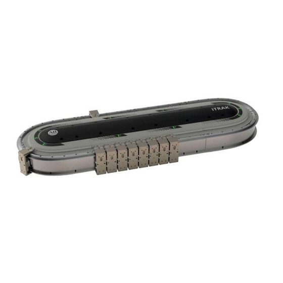
The iTRAK 5730 system is a modular, scalable, linear motor system. This About the iTRAK 5730 system provides independent control of multiple movers on straight or System curvilinear paths. The iTRAK 5730 system is built from a combination of the following modules and components: • Straight motor modules •... - Page 12 Each motor module can operate and control multiple movers. Motor over-temperature protection is provided by temperature sensors that are embedded in the motor coils of the motor modules. The iTRAK 5730 system does not provide electronic motor over-temperature protection.
- Page 13 Chapter 1 Before You Begin Installation Figure 1 - Exploded View of the Servo and Mechanical Components of an iTRAK 5730 System Item Component Item Component Curved motor module Mounting ring (top) Straight motor module Mounting ring (bottom) Power and control input connector module Mover —...
- Page 14 A Kinetix 5700 DC-bus power supply (2198) and Kinetix 5700 iTRAK power supply (2198T) provide the DC Power circuitry and 2198-Pxxx (DC-bus) bus voltages that are required for the iTRAK 5730 motor modules. The Kinetix 5700 power supply is used components 2198T-W25K-ER (iTRAK) with other Kinetix 5700 components and branch circuit protection.
-
Page 15: Catalog Number Explanations
System with an iTRAK Power Supply on page 66. Catalog Number The modular, scalable design of the iTRAK 5730 allows you to purchase an assembled system or individual components so you can build a system that is Explanations suited to your specific application. -
Page 16: Modular Itrak 5730 System Components
Chapter 1 Before You Begin Installation Modular iTRAK 5730 System Components All iTRAK 5730 system component catalog numbers begin with the Bulletin number 2198T followed by a character that represents one of these module types: • C - Cable or connector •... - Page 17 Chapter 1 Before You Begin Installation Connector Module Catalog Numbers These tables provide an example catalog number explanation for a connector module. For example: 2198T-CT-CP 2198T Bulletin Number Module Type Input Option Code Description Code Description Code Description Connector terminal 2198T iTRAK Intelligent Track System Communication and power inputs...
- Page 18 Chapter 1 Before You Begin Installation Mover Magnet Plate Catalog Numbers These tables provide an example catalog number explanation for a mover magnet plate. For example: 2198T-M0304-A000-SS 2198T Bulletin Number Module Type Coil Length Magnet Length Code Description Code Description Code Description Code...
-
Page 19: Motor Modules
Chapter 1 Before You Begin Installation Motor Modules Your iTRAK 5730 system can use two types of motor modules. Figure 2 shows the features of the straight motor module and Figure 3 shows the features of the curved motor module. -
Page 20: Motor Module Status Indicators
Chapter 1 Before You Begin Installation Motor Module Status Indicators The motor modules (2198T-L20-T0303-A00-S2 and 2198T-L20-T0309-D18-S2) contain the following status indicators. For a description of these status indicators, see Motor Module Status Indicators on page 115. Top View Straight Motor Module (Catalog Number 2198T-L20-T0303-A00-S2) shown. Rockwell Automation Publication 2198T-UM003A-EN-P - May 2020... -
Page 21: Connector Modules
Chapter 1 Before You Begin Installation Connector Modules The iTRAK 5730 system can use three types of connector modules: • Figure 4 shows the features of the power and control input connector module. This connector module provides a power source and Ethernet connection for the iTRAK 5730 system. - Page 22 Chapter 1 Before You Begin Installation Figure 5 - 2198T-CT-P Power Input With Control Pass-through Connector Module Power Input with Control Pass-through Connector-module Components Item Description Item Description Incoming power bus connector Ground connector Power status indicator Pass-through Ethernet network connectors Motor power and ground bus connector Figure 6 - 2198T-CT Power and Control Pass-through Connector Module Power and Control Pass-through Connector-module Components...
-
Page 23: Connector Module Status Indicators
The mounting rings are used to connect motor modules and provide rigidity to Mounting Rings the iTRAK 5730 system. Each mounting ring includes the hardware that is required to connect to the motor modules. An equal number of top and bottom mounting rings are required for installation. -
Page 24: Rectangular And Flat Rails
Chapter 1 Before You Begin Installation Rectangular and Flat Rails The straight rectangular and flat rail kits are installed on the straight motor modules. Straight rectangular and flat rail kits are available in 300 mm (11.8 in.), 600 mm (23.6 in.), and 900 mm (35.4 in.) lengths. Each kit contains two straight rectangular rails and rectangular rail wedges and two straight flat rails and flat rail wedges. - Page 25 Chapter 1 Before You Begin Installation The curved rectangular and flat rails are installed on the curved motor modules. Curved rectangular and flat rails (2198T-BE-ED18) are approximately 900 mm (35.4 in.) long. Each kit contains two curved rectangular rails and straight rectangular rail wedges and four curved flat rails and two flat wedges.
-
Page 26: Mover
Chapter 1 Before You Begin Installation Mover Movers are 50 mm (2.0 in.) long, in the direction of travel. See the iTRAK 5730 System Technical Data, publication 2198T-TD002 for the force-speed curves. Do not exceed the force-speed parameters when programming your system. -
Page 27: Power Supplies
Chapter 1 Before You Begin Installation Power Supplies Power is supplied to the iTRAK 5730 system by using a scalable Kinetix 5700 iTRAK power supply. See Provide Power to the iTRAK System on page more information on the required iTRAK power supply and system power requirements. -
Page 28: Typical Communication Configurations
Chapter 1 Before You Begin Installation Typical Communication The iTRAK 5730 system supports linear, ring (Device Level Ring), and star Ethernet topologies, by using ControlLogix, GuardLogix, CompactLogix, or Configurations Compact GuardLogix controllers and Stratix® Ethernet switch (where applicable). The power and control input connector module (cat. no. 2198T-CT-CP) -
Page 29: Device Level Ring Topology
DLR network. Only switches can operate as redundant gateways. For more information about DLR, see the EtherNet/IP Device Level Ring Application Technique, publication ENET-AT007. Figure 13 - iTRAK 5730 System Ring Communication Installation Ethernet Cable Ethernet... -
Page 30: Star Topology
The iTRAK 5730 connector modules have dual ports, so linear topology is maintained from one module to another, but the iTRAK 5730 system and other devices operate independently. The loss of one device does not impact the operation of other devices. -
Page 31: Safety Information
See the iTRAK 5730 System Technical Data, publication 2198T-TD002 for operational ratings. Do not exceed these ratings. • The iTRAK 5730 system must only be used in the environment specified. • Chapter 2 - Track Installation and Kinetix 5700 iTRAK Power Supply and iTRAK Bus Conditioner Module Installation Instructions, for system installation instructions. -
Page 32: Machine Guarding
National Electrical Code (NEC) and local codes outline provisions for safe installation of electrical equipment. ATTENTION: A hazard of personal injury or equipment damage exists. An E-stop is not provided with the iTRAK 5730 System. Consult your national and local electrical codes and provide an E-stop if necessary. •... -
Page 33: Avoid Accidents, Injury, And Property Damage
Temperatures of the motor-module stator covers can be higher than 60° C (140° F) during or after operation. After you remove power from the iTRAK 5730 system, motor modules can require up to 140 minutes to cool. Let the motor modules cool before you touch or service the system. -
Page 34: Protection Against Magnetic And Electromagnetic Fields
Magnetic Field Strength The iTRAK 5730 system movers contain components with strong magnetic fields. The motor modules also produce magnetic fields while movers are being commanded. This section provides the strength of the magnetic field for an uninstalled mover, installed and enabled mover, and uninstalled position magnet. - Page 35 Chapter 1 Before You Begin Installation Table 5 lists the magnetic field strength at distances from the center point of an uninstalled mover. Maintain these minimum distances to avoid interaction with the magnetic field. Table 5 - Magnetic Field Strength of an Uninstalled Mover Magnetic Strength 0.05 mT 0.1 mT...
-
Page 36: Safe Magnet Handling
Strong magnets can erase magnetic media. Never let credit cards or electronic media contact or get near the mover and motor magnet or iTRAK 5730 system. • The track creates strong magnetic fields while energized during operation. -
Page 37: Itrak 5730 System Installation
Approximate Dimensions Assemble an iTRAK 5730 System Mount the iTRAK 5730 Assembly Install the Lubrication System Optional Infield Covers Consider the following when planning the location for your iTRAK 5730 installation: • Overall finished assembly dimensions • Future product expansion •... -
Page 38: Before You Begin
5730 System Installation Before You Begin Review the information in this section before you begin assembly or maintenance on your iTRAK 5730 system. Tools and Accessories Table 8 provides a list of the tools that are required to assemble and install an iTRAK 5730 system. -
Page 39: General Handling Instructions
System Components This section identifies the modules and components that are required to assemble an iTRAK 5730. Use this section to verify that you have received the parts that are required for each kit in your installation. Table 9 - iTRAK 5730 System Components... -
Page 40: Inspection
• 6, O-rings • 25 m (82 ft) 4 x 2.5 mm polymer tubing When you receive your iTRAK 5730 kits and components, inspect each kit for Inspection damage or missing items. If there is evidence of damage or loss, follow this procedure: •... -
Page 41: Approximate Dimensions
(13.8 in.) (11.8 in.) Assemble an iTRAK 5730 This section provides instructions to assemble an iTRAK 5730 system. This installation provides instructions for assembling a closed track iTRAK 5730 System system, with a minimum of two curved and two straight motor modules. Your track can be made with more straight motor modules than are shown in these procedures, but the same instructions apply. -
Page 42: Before You Begin
This procedure requires lifting equipment and hardware capable of supporting the full assembled weight of the product. To prepare the appropriately rated lifting equipment, you must calculate the full assembled weight of your iTRAK 5730 system. S Table 9 on page for iTRAK 5730 components and kits weights. -
Page 43: Install Top Structural Mounting Rings
Chapter 2 iTRAK 5730 System Installation Install Top Structural Mounting Rings 1. With the upper surface facing up (side with status indicators), place a curved motor module on a flat and level work surface. 2. With the counter-bored holes visible (up), place a structural mounting ring into the inner motor module surface. - Page 44 Chapter 2 iTRAK 5730 System Installation 8. Repeat steps 5…7 to install a second straight motor module across from the first straight motor module. M6 x 20 mm 4 mm 6.8 N m (60 lb • • 9. With the counter-bored holes visible (up), place a second structural mounting ring into the inner straight motor-module surfaces.
- Page 45 Chapter 2 iTRAK 5730 System Installation Install Closing Curved Motor Module 1. With the upper surface facing up (side with status indicators), place a second curved motor module on a flat and level work surface. 2. With the counter-bored holes visible (up), place a structural mounting ring into the inner curved motor module surface.
-
Page 46: Install Bottom Structural Mounting Rings
ATTENTION: To guard against possible personal injury and equipment damage, take these precautions when lifting the iTRAK 5730 assembly: • Inspect all lifting hardware for proper attachment before lifting the equipment. • Do not allow any part of the equipment or lifting mechanism to contact electrically charged conductors or components. -
Page 47: Install Bottom Flat Rails And Flat Wedges
Chapter 2 iTRAK 5730 System Installation 9. Place a rubber O-ring in each of the two lubrication system openings on each of the curved motor modules. A drop of oil can help to keep the rubber O-ring in place. Install Bottom Flat Rails and Flat Wedges 1. - Page 48 Chapter 2 iTRAK 5730 System Installation 5. With the counter-bored holes visible (up), place the straight flat rail components on the motor modules. 6. Insert and finger-tighten an M4 x 8 mm Torx screw in each of the counter-board holes on the flat rail sections.
- Page 49 Chapter 2 iTRAK 5730 System Installation 13. On the same end of the rail system, align a flat rail wedge with the straight and curved rail sections on either side of the wedge. There must be no gaps between the edges of the wedge and long rail IMPORTANT sections and the outward facing edges must align.
-
Page 50: Install Bottom Rectangular Rails
Chapter 2 iTRAK 5730 System Installation 18. When all flat rails are in alignment, apply final torque to all screws. M4 x 8mm 4.0 N m (35 lb • • Install Bottom Rectangular Rails 1. Place and seat a rubber O-ring in each of the two lubrication system openings on a curved rectangular-rail section. - Page 51 Chapter 2 iTRAK 5730 System Installation 2. With the counter-bored holes visible (up), place a curved rectangular rail on the curved flat rail until it is fully seated against the flat rail below. The motor modules contain pins along the surface that are used to locate the rails properly.
-
Page 52: Install Rectangular Wedges And Align Rectangular Rails
Chapter 2 iTRAK 5730 System Installation Install Rectangular Wedges and Align Rectangular Rails Start with the two wedges on each end of the curved sections first. IMPORTANT 1. Begin with the gap between a curved and straight rail section, and, with the counter-bored holes visible (up), place a rectangular wedge in the gap between the rectangular rails. - Page 53 Chapter 2 iTRAK 5730 System Installation 4. While you press downward on the rail alignment tool to verify that the tool is in full contact with the rails, lock the tool clamps. 5. Apply final torque to screws in the wedge.
-
Page 54: Install Top Rails, Wedges, And Connector Modules
ATTENTION: To guard against possible personal injury and equipment damage, take these precautions when lifting the iTRAK 5730 assembly: • Inspect all lifting hardware for proper attachment before lifting the equipment. • Do not allow any part of the equipment or lifting mechanism to contact electrically charged conductors or components. - Page 55 M4 Retained Screw #2 Phillips 2.3 N m (20 lb • • You have completed the iTRAK 5730 assembly. Next steps: • Mount the iTRAK 5730 assembly - see page • Install the lubrication system - see page • Install the position magnets on the movers - see page •...
-
Page 56: Mount The Itrak 5730 Assembly
Chapter 2 iTRAK 5730 System Installation Mount the iTRAK 5730 Use the information in this section to prepare the iTRAK 5730 system for lifting and mounting. A customer-sourced mounting system is required to mount the Assembly iTRAK 5730 in the desired position and location. -
Page 57: Grounding Requirements
Chapter 2 iTRAK 5730 System Installation ATTENTION: Installed connector modules extend approximately 0.54 mm (0.02 in.) above the surface of the top structural mounting rings. You must use a 1 mm (0.04 in.) or larger spacer between the top structural mounting rings and a mounting plate or similar mounting assembly when secured at a 90°... -
Page 58: Before You Lift And Mount The Itrak 5730 Assembly
Chapter 2 iTRAK 5730 System Installation Before You Lift and Mount the iTRAK 5730 Assembly Follow these guidelines to avoid personal injury or equipment damage. ATTENTION: There is a risk of injury by improper handling. You can be injured by being crushed, cut, struck, or sheared while handling system components. -
Page 59: Lift The Itrak 5730 Assembly
5730 system. Do not lift or move the equipment by any means other than what is described in this publication. -
Page 60: Install The Lubrication System
Chapter 2 iTRAK 5730 System Installation Install the Lubrication The iTRAK 5730 lubrication system, catalog number 2198T-AL-SYS-4, comes with a coil of tube to connect system fittings to the remotely located pumps System and system fittings. Four pump assemblies are included in the system; one is intended for each bearing rail. -
Page 61: What You Need
1. Locate a mounting position for the pumps. The pump must be located within the 10 m (32.8 ft) of tube routing distance to the iTRAK 5730 system lubrication connectors and 5.0 m (16.4 ft) of the power cable routing distance to 24V I/O port of your controller. -
Page 62: Wire Lubrication Pump
Lubrication on page 154 to make tube connections, initial lubrication, and lubrication during normal operation. Optional Infield Covers The iTRAK 5730 system has optional infield section covers that provide additional ingress protection. What You Need • 10 mm hexagonal socket •... - Page 63 Chapter 2 iTRAK 5730 System Installation 3. Repeat step 1 step 2 for the remaining covers. M6 x 35 mm 10 mm 4.5 N m (40 lb • • Rockwell Automation Publication 2198T-UM003A-EN-P - May 2020...
- Page 64 Chapter 2 iTRAK 5730 System Installation Notes: Rockwell Automation Publication 2198T-UM003A-EN-P - May 2020...
-
Page 65: Connect The Itrak 5730 System
Use this chapter with the Kinetix® 5700 iTRAK Power Supply and iTRAK Bus Conditioner Module Installation Instructions, publication 2198T-IN001 install and connect the Kinetix 5700 iTRAK power supply to an iTRAK 5730 system. For detailed information on how to install a Kinetix 5700 iTRAK power supply into a Kinetix 5700 system, see the Kinetix 5700 Servo Drives User Manual, publication 2198-UM002. -
Page 66: Typical Itrak 5730 System
Connect the iTRAK 5730 System Typical iTRAK 5730 System Figure 25 provides a complete view of a typical iTRAK 5730 system that includes required and customer-supplied components, iTRAK solutions, and wiring. Figure 25 - Typical iTRAK System with an iTRAK Power Supply... -
Page 67: Provide Power To The Itrak System
It is recommended that you install connector module catalog numbers 2198T-CT-CP and 2198T-CT-P, which connect DC-bus and 24V DC control power to the iTRAK 5730 system, on a curved motor module to provide maximum system power. Power, which is connected to the input power connector on the module, flows through the bottom output connector on the opposite end the module (as shown here). -
Page 68: One Itrak Power Supply
The power flow through the modules is shown in the diagram and identifies where the power connector modules are installed. Figure 26 - Wire an iTRAK 5730 System with an iTRAK Power Supply Power Input With Control Pass-through Power and Control Pass-through... -
Page 69: Connect The Power Cable
SHOCK HAZARD: Do not make any cable connections when power is applied to any component in the iTRAK 5730 system. To avoid a shock hazard, verify that system power is not applied before you begin the procedures in this chapter. -
Page 70: Connect An Ethernet/Ip Network To The Itrak 5730 System
IP addresses can be changed through the Module Configuration dialog box in RSLinx software. This is the default setting. Reserved. Applying power to the iTRAK 5730 system with the switches set to a reserved All other values value results in an “Illegal Address”... - Page 71 Chapter 3 Connect the iTRAK 5730 System Before changing the EtherNet/IP address rotary switch settings to 888, IMPORTANT consider the following: • Restoring the factory default settings clears all functional safety configurations, resets safety ownership, and returns the motor module to the out-of-box-state.
-
Page 72: Communication Control Dip Switch
The communication control DIP switch (S4) is used to identify the backplane communication master for an iTRAK 5730 system and enables or disables access to the iTRAK 5730 diagnostic webpage. DIP switch S4 is contained on the power and control input connector module (cat. no. 2198T-CT-CP). See Figure 28 on page 70 for switch location. -
Page 73: Connect The Ethernet Cable
‘ON,’ defining the module as the backplane communication master. DIP switch S4-1 on the power and control connector 2 must be set to “OFF.” Figure 30 - iTRAK 5730 System with Multiple Ethernet Networks and Static IP Addresses iTRAK 5730 System... - Page 74 Chapter 3 Connect the iTRAK 5730 System 2. Verify that the connector pins are aligned and insert the Ethernet cable connector into the Ethernet connector on the connector module. Connector Module Ethernet Port Connector Ethernet Cable (cat. no. 1585D-E8TGJM-xx) 3. By turning the cable outer housing clockwise, secure the cable to the connector module mounting ring until the cable is fully seated.
-
Page 75: Studio 5000 Logix Designer
Understand Bus-sharing Group Configuration Commission the iTRAK 5730 System Tune the Axes To configure your iTRAK 5730 system, use a personal computer and the Studio Studio 5000 Logix Designer 5000 Logix Designer® application, version 33 or later. For help with using the Studio 5000 Logix Designer application as it applies to configuring the ControlLogix®... -
Page 76: Configure The Itrak 5730 System
The IP address rotary switches on the power and control input connector module are set to ‘999’ with DHCP enabled at the factory. Follow these steps to set the iTRAK 5730 system to static IP addresses on the power and control input connector module (cat. no. 2198T-CT-CP). -
Page 77: Protected Mode
Configure and Start Up the iTRAK 5730 System Protected Mode The iTRAK 5730 system supports Protected Mode. When the system is in Protected Mode, the motor modules do not allow any configuration changes, resets, or firmware updates when a controller connection is open. Protected Mode is enabled by default. -
Page 78: Configure And Customize The Project File
Chapter 4 Configure and Start Up the iTRAK 5730 System Configure and Customize These procedures assume that you have wired your iTRAK 5730 system. In this example, the GuardLogix® 5584ES safety controller dialog boxes are shown. the Project File Configure the Controller Follow these steps to configure the controller. - Page 79 Chapter 4 Configure and Start Up the iTRAK 5730 System The New Project dialog box appears. 6. From the Revision pull-down menu, choose your software version. 7. Click Finish. The new controller appears in the Controller Organizer under the I/ O Configuration folder.
-
Page 80: Configure The Kinetix 5700 Power Supply
1. Below the controller you created, right-click Ethernet and choose New Module. The Select Module Type dialog box appears. 2. By using the filters, check Motion and Allen-Bradley, and select your 2198-Pxxx DC-bus power supply as appropriate for your hardware configuration. - Page 81 Chapter 4 Configure and Start Up the iTRAK 5730 System The New Module dialog box appears. 4. Configure the new module. a. Type the module Name. b. Select an Ethernet Address option. In this example, the Private Network address is selected.
- Page 82 Chapter 4 Configure and Start Up the iTRAK 5730 System ATTENTION: To avoid damage to equipment all modules physically connected to the same shared-bus connection system must be part of the same Bus Sharing Group in the Logix Designer application.
- Page 83 Chapter 4 Configure and Start Up the iTRAK 5730 System 14. Click New Axis. The New Tag dialog box appears. 15. Type the axis Name. AXIS_CIP_DRIVE is the default Data Type. 16. Click Create. The axis (Axis_Converter in this example) appears in the Controller Organizer under Motion Groups >...
-
Page 84: Configure The Itrak 5730 Power Supply
Chapter 4 Configure and Start Up the iTRAK 5730 System Configure the iTRAK 5730 Power Supply Follow these steps to configure the iTRAK 5730 DC-bus power supply. 1. Below the controller you just created, right-click Ethernet and choose New Module. - Page 85 Bus Regulator Action Disabled Disables the internal shunt resistor and external shunt option. (1) Shared DC/DC bus configuration is the default selection for iTRAK 5730 DC-bus power supplies. (2) For more information on bus-sharing groups, see Understand Bus-sharing Group Configuration on page 104.
- Page 86 Chapter 4 Configure and Start Up the iTRAK 5730 System 11. Click the Digital Input category. 12. From the Digital Input pull-down menu choose Enable or Unassigned, depending on your application. 13. Click the Associated Axes category. 14. Click New Axis.
-
Page 87: Configure The Itrak 5730 Motor Modules
1. Above the DC-bus power supply (converter) you just created, right-click Ethernet and choose New Module. The Select Module Type dialog box appears. 2. By using the filter, enter iTRAK, and select the iTRAK 5730 Intelligent Track System, Section. 3. Click Create. - Page 88 Chapter 4 Configure and Start Up the iTRAK 5730 System The New Module dialog box appears. Example New Module Dialog Box with GuardLogix Controller Selections 4. Configure the new motor module properties. a. Type the module Name. b. Select an Ethernet Address option.
- Page 89 Chapter 4 Configure and Start Up the iTRAK 5730 System 6. Define the motor module. a. Select your Electronic Keying option from the pull-down menu (Compatible Module is the default setting). b. From the Safety Application pull-down menu, choose between Safety Off or Networked for an integrated safety application.
- Page 90 Otherwise, go to Continue iTRAK 5730 Motor Module Configuration page 92. 13. Click the Safety category. 14. The connection between the owner and the iTRAK 5730 motor module is based on the following: • Servo drive • GuardLogix slot number •...
- Page 91 Chapter 4 Configure and Start Up the iTRAK 5730 System 15. Click Advanced. The Advanced Connection Reaction Time Limit Configuration dialog box appears. Analyze each safety channel to determine the appropriate settings. The smallest Input RPI allowed is 6 ms. Selecting small RPI values consumes network bandwidth and can cause nuisance trips because other devices cannot get access to the network.
-
Page 92: Continue Itrak 5730 Motor Module Configuration
Configure and Start Up the iTRAK 5730 System Continue iTRAK 5730 Motor Module Configuration Follow these steps to configure the axes for your iTRAK 5730 system motor modules. 1. Right-click the iTRAK 5730 motor module you just created and choose Properties. - Page 93 Chapter 4 Configure and Start Up the iTRAK 5730 System 5. From the Section Motor pull-down menu, select the section motor corresponding to your motor module. A curved motor module is comprised of three individual sections: IMPORTANT curve section A, curve section B, and curve section C. Each of the three curve sections needs to be added as a separate motor module and configured individually.
- Page 94 Configure and Start Up the iTRAK 5730 System 8. Select the Associated Axes Category. For each iTRAK 5730 motor module, five axes are possible; one section axis and up to four mover axes. • Axis 1 is the section axis.
- Page 95 Chapter 4 Configure and Start Up the iTRAK 5730 System 11. Click Create. The axis (Axis_1 in this example) appears in the Controller Organizer under Motion Groups> Ungrouped Axes and is assigned as Axis_1. 12. To configure a Mover axis, next to Axis n (Mover), click New Axis.
-
Page 96: Configure The Motion Group
Chapter 4 Configure and Start Up the iTRAK 5730 System Configure the Motion Group Follow these steps to configure the motion group. 1. In the Controller Organizer, right-click Motion Groups and choose New Motion Group. The New Tag dialog box appears. - Page 97 Chapter 4 Configure and Start Up the iTRAK 5730 System The Motion Group Properties dialog box appears. 5. On the Axis Assignment tab, select and add each of your axes (created earlier) to the Assigned category. 6. Click the Attribute tab and edit the default values as appropriate for your application.
-
Page 98: Configure The Section Axis Properties
The General dialog box appears. 3. In the Associated Module section, in the Module pull-down menu, verify the name of the associated module. The iTRAK 5730 system catalog number appears in the Module Type and Power Structure fields. 4. Click Apply. - Page 99 Chapter 4 Configure and Start Up the iTRAK 5730 System 5. Select the Actions category. From this dialog box, you can program actions and change the action for exceptions (faults). For more information on configuration selections, see iTRAK 5730 Motor Section and Mover Behavior on page 121.
-
Page 100: Configure The Mover Axis Properties
Chapter 4 Configure and Start Up the iTRAK 5730 System Configure the Mover Axis Properties Follow these steps to configure mover axis properties. 1. In the Controller Organizer, right-click a mover axis and choose Properties. 2. Select the General category. - Page 101 6. In the Associated Module section, from the Module pull-down menu, verify the name of the associated module. The iTRAK 5730 system catalog number appears in the Module Type and Power Structure fields. 7. To save your changes, click Apply.
- Page 102 Chapter 4 Configure and Start Up the iTRAK 5730 System 8. Select the Scaling Category and edit the default values as appropriate for your application. The Unwind value is the same as the overall length of your track. 9. To save any changes, click Apply.
-
Page 103: Download The Program
Chapter 4 Configure and Start Up the iTRAK 5730 System 12. Select the Actions category and program any actions and change the action for exceptions (faults) as appropriate for your application. 13. Select the Parameter List category and edit the values for different parameters as appropriate for your application. -
Page 104: Apply Power To The Itrak 5730 System
5730 System SHOCK HAZARD: To avoid a hazard of electrical shock, complete all installation and power connections of the iTRAK 5730 system components prior to applying power. Once power is applied, connector terminals can have voltage present even when not in use. -
Page 105: Bus-Sharing Groups Example
Bus-sharing Groups Example Figure 31 12 iTRAK 5730 motor module sections are needed to support the motion application. All 12 section axes are configured in the same Motion group in the Logix Designer application. However, the 12 motor module sections are also configured as 2 bus-sharing groups. - Page 106 Chapter 4 Configure and Start Up the iTRAK 5730 System Figure 31 - Bus-sharing Groups Example 2198T-CHBFLS8-12AAxx, power cable iTRAK 5730 System 2198-Pxxx 2198T-W25K-ER 2198T-W25K-ER Kinetix 5700 Kinetix 5700 Kinetix 5700 Section_04 Section_03 Section_07 Section_06 Section_05 Power Supply iTRAK Power...
-
Page 107: Configure Bus-Sharing Groups
Configure Bus-sharing Groups In both groups, the Bus Configuration for the iTRAK power supply is Shared DC/DC and the Bus Configuration for the iTRAK 5730 system is Shared DC. Figure 32 - Group 1 iTRAK 5730 Power Supply Configuration Figure 33 - Group 2 iTRAK 5730 System Configuration... - Page 108 Chapter 4 Configure and Start Up the iTRAK 5730 System Figure 34 - Group 3 iTRAK Power Supply Configuration Figure 35 - Group 3 iTRAK 5730 System Configuration Rockwell Automation Publication 2198T-UM003A-EN-P - May 2020...
-
Page 109: Commission The Itrak 5730 System
This procedure assumes that you have configured your iTRAK 5730 system, your Logix 5000 controller, and applied power to the system. Before you commission the iTRAK 5730, verify that the MOD and NET status IMPORTANT indicators are operating as described in Interpret Status Indicators on page 115. -
Page 110: Calculate And Store Position Gap Compensation Values
3. For all motor modules, change the ‘Mover Axis Assignment Sequence’ field back to the original value. 4. Repeat the gap position compensation procedure. This procedure assumes that you have configured your iTRAK 5730 system, Tune the Axes your Logix 5000 controller, and applied power to the system. - Page 111 Configure and Start Up the iTRAK 5730 System Re-attach the load if it was disconnected. ATTENTION: If the iTRAK 5730 system has not been enabled before (new installation), verify that you have safeguards in place to safely remove power from the drive in the event of an unstable situation where the drive can produce undesired motion.
- Page 112 From the Adaptive Tuning Configuration pull-down menu, choose Tracking Notch. d. Click Apply. 6. Enable the iTRAK 5730 system for a few seconds with an MSO instruction or motion direct command, followed by an MSF instruction or motion direct command, to make sure that no audible squealing noise is present.
-
Page 113: Troubleshoot The Itrak 5730 System
Knowledgebase Answer ID 1092901 iTRAK 5730 System Fault Codes has the fault codes. Download the spreadsheet from this public article. You might be asked to login to your Rockwell Automation web account, or create an account if you do not have one. You do not need a support contract to access the article. -
Page 114: Fault Code Overview
For more information, see Integrated Motion on the EtherNet/IP™ Network Reference Manual, publication MOTION-RM003. The iTRAK 5730 maintains a fault log of the last 128 faults. The fault log includes time stamps and is stored in persistent memory. However, the fault log cannot be cleared on the module. -
Page 115: Interpret Status Indicators
Do not attempt to use status indicators to determine operational status. Motor Module Status Indicators The iTRAK 5730 motor modules contain the following status indicators. Top View Straight Motor Module (Catalog Number 2198T-L20-T0303-A00-S2) Shown. - Page 116 Chapter 5 Troubleshoot the iTRAK 5730 System Table 17 - Module (MOD) Status Indicator Descriptions Condition Status Steady Off There is no power applied to the motor module section. Steady Green The motor module section is operational. No faults or failures.
-
Page 117: Connector Module Status Indicators
Chapter 5 Troubleshoot the iTRAK 5730 System Connector Module Status Indicators The iTRAK 5730 power and control input and power input with control pass- through connector modules contain the following status indicators. Top View Power and Control Input Connector Module (Catalog Number 2198T-CT-CP) Shown. -
Page 118: Axis Troubleshooting
Chapter 5 Troubleshoot the iTRAK 5730 System Axis Troubleshooting These conditions do not always result in a fault code, but can require troubleshooting to improve iTRAK 5730 performance. Table 22 - Axis Troubleshooting Condition Potential Cause Possible Resolution Unintentionally in Torque mode. -
Page 119: Logix 5000 Controller And Itrak System Behavior
NODE ALARM xxx faults do not apply because they do not trigger stopping behavior. The iTRAK 5730 motor sections and movers support fault actions for Ignore, Alarm, Minor Fault, and Major Fault as defined in Table 23. -
Page 120: Itrak 5730 Power Supply Behavior
5730 Power Supply Behavior See the iTRAK 5730 Power Supply Behavior section in Chapter 7 of the Kinetix 5700 Servo Drive User Manual, publication 2198-UM002, for details. Rockwell Automation Publication 2198T-UM003A-EN-P - May 2020... -
Page 121: Itrak 5730 Motor Section And Mover Behavior
Chapter 5 Troubleshoot the iTRAK 5730 System iTRAK 5730 Motor Section and Mover Behavior For the iTRAK 5730 motor sections and movers, only selected exceptions are configurable. Table 25 provides a list and descriptions of the available configurable stopping actions. - Page 122 When the Safe Torque Off Action Source is set to “Connected Drive,” the connected motor module performs the configured Safe Torque Off Action. For an iTRAK 5730 motor module section, a “Current Decel & Disable” stopping action only maintains the enabled state of the section axis for the configured stopping time limit before activating the brake control bit and disabling the section axis.
- Page 123 Axis 1 Unassociated Section Axis — SECTION AXIS (section axis). All iTRAK 5730 motor module sections must have an associated section axis. A motor module section has not provided its axis and mover INIT FLT M28 - TRACK Track Configuration Error information to the rest of the track when expected.
- Page 124 Chapter 5 Troubleshoot the iTRAK 5730 System Table 30 - Motor Section and Mover Fault Behavior, NODE FLT Fault Codes Section Axis Mover Axis Fault Action Fault Action Best Available Best Available Exception Fault Code Exception Text Stopping Action Stopping Action...
-
Page 125: Maintenance
You must determine through best engineering practices how often to perform the following procedure. Before You Begin ATTENTION: Before attempting any service to an iTRAK 5730 system See Safety Information on page Rail System Clean all rail surfaces. -
Page 126: Install Or Replace Components
The procedures in this section describe how to install or replace system components. Components The iTRAK 5730 motor modules and safety-related system do not contain IMPORTANT serviceable parts. No repair option is provided in the event of a motor module defect. -
Page 127: Install Or Remove A Position Magnet Assembly
Install or Remove a Position Magnet Assembly Use this procedure to install or remove a position magnet assembly. Before You Begin ATTENTION: Before attempting any service to an iTRAK 5730 system. See Safety Information on page ATTENTION: A hazard of personal injury or equipment damage exists. The motor magnet protective cover must be installed on an un-installed mover at all times. -
Page 128: Install Or Replace A Mover
Install or Replace a Mover Use this procedure to install or replace a mover. Before You Begin ATTENTION: Before attempting any service to an iTRAK 5730 system. See Safety Information on page ATTENTION: A hazard of personal injury or equipment damage exists. The motor magnet protective cover must be installed on an un-installed mover at all times. - Page 129 Chapter 6 Maintenance Choose an accessible straight track section next to a curved section of the track where you can remove the top and bottom rectangular wedges and rails. A top flat rail must also be removed. To replace a mover, position the mover over the curved motor module next to the selected straight motor module.
- Page 130 Chapter 6 Maintenance 2. Remove the M4 x 20 mm screws from the top and bottom rectangular rails on same section. Remove the rails. 3. Remove the M4 x 8 mm screws from the top flat rail section. Do not remove the bottom flat rail section. IMPORTANT Rockwell Automation Publication 2198T-UM003A-EN-P - May 2020...
- Page 131 Chapter 6 Maintenance 4. Place the mover loader tool against the rectangular rail section. 5. Secure the mover loader tool to the assembly using two M4 x 8 mm screws. 6. Install or replace your mover. Install a Mover • As you install a mover, the mover loader tool extracts the motor- magnet protective cover.
- Page 132 Chapter 6 Maintenance Remove a Mover a. Place the motor-magnet protective cover in the loader tool. b. The protective cover is secured to the motor magnet as you remove the mover from the track. There may be some resistance when pushing the mover across the tool/track interface.
- Page 133 Chapter 6 Maintenance 10. Replace the rectangular rails and tighten the middle hardware only. 11. Replace rectangular wedges and hand-tighten all hardware. 12. Align the rectangular wedges using the rail alignment tool and torque hardware to 4 N•m (35 in•lb). 13.
-
Page 134: Replace A Straight Motor Module
Replace a Straight Motor Module Use this procedure to replace a straight motor module. The iTRAK 5730 motor modules and safety-related system do not contain IMPORTANT serviceable parts. No repair option is provided in the event of a motor module defect. - Page 135 Chapter 6 Maintenance 5. Remove the M4 x 20 mm screws from the top and bottom rectangular rails and remove the rails. 6. Remove the M4 x 8 mm screws from the top and bottom flat rail section and remove the rails. Rockwell Automation Publication 2198T-UM003A-EN-P - May 2020...
- Page 136 Chapter 6 Maintenance 7. Remove M4 x 8 mm hardware from the flat wedges on either side of the section being removed. 8. Remove the first M4 x 20 mm hardware from either side of the adjacent rectangular sections and remove the wedges. ATTENTION: The rail components are sharp.
- Page 137 Chapter 6 Maintenance 9. Remove the M6 x 20 mm screws from the two bottom structural mounting rings that are connected to the module being replaced. Retain the screws for reuse. 10. Remove M6 x 20 mm screws from the top structural mounting ring. Retain the screws for reuse.
- Page 138 Chapter 6 Maintenance 11. Carefully slide the module out of the system and replace with the new straight motor module section. If the motor module cannot be easily removed, loosen adjacent mounting ring bolts (but do not remove). 12. Reassemble the module in the reverse order of removal. Follow these steps in order to reassemble the module.
-
Page 139: Replace A Curved Motor Module
Replace a Curved Motor Module Use this procedure to replace a curved motor module. The iTRAK 5730 motor modules and safety-related system do not contain IMPORTANT serviceable parts. No repair option is provided in the event of a motor module defect. - Page 140 Chapter 6 Maintenance 5. Remove all M4 x 20 mm hardware from the top and bottom rectangular rails from the curved motor module. Remove the rails. Retain the o-rings for reuse. IMPORTANT 6. Remove all M4 x 8 mm hardware from the top and bottom flat rails from the curved motor module.
- Page 141 Chapter 6 Maintenance 7. Remove the M6 x 20 mm screws from the top structural mounting ring. Retain the screws for reuse. 8. Remove the M6 x 20 mm screws from the bottom structural mounting ring. Retain the screws for reuse. 9.
-
Page 142: Replace Top And Bottom Rectangular Straight Rails
You must also perform the rail alignment procedure. Follow these steps to replace top and bottom rectangular straight rails. Before you Begin ATTENTION: Before attempting any service to an iTRAK 5730 system. Safety Information on page What You Need •... -
Page 143: Replace Top And Bottom Rectangular Curved Rails
Replace Top and Bottom Rectangular Curved Rails Follow these steps to replace top and bottom rectangular curved rails. Before you Begin ATTENTION: Before attempting any service to an iTRAK 5730 system. See Safety Information on page What You Need •... - Page 144 Chapter 6 Maintenance 2. Place and seat a rubber o-ring in each of the two lubrication system openings on a curved rectangular-rail section. A drop of oil can help to keep the rubber o-ring in place. 3. With the counter-bored holes visible (up) of the new rail, place on the curved rectangular rail until it is fully seated against the flat rail below.
-
Page 145: Replace Top And Bottom Flat Straight Rails
Maintenance Replace Top and Bottom Flat Straight Rails Follow these steps to replace top and bottom flat straight rails. Before you Begin ATTENTION: Before attempting any service to an iTRAK 5730 system. See Safety Information on page What You Need •... - Page 146 Chapter 6 Maintenance 7. With the counter-bored holes visible (up), place the straight flat rail on the motor module. 8. Insert and finger-tighten an M4 x 8 mm Torx screw in each of the counter-board holes. 9. Loosen each of the M4 x 8 mm Torx screws one half turn. The screw heads should remain in the counter-bore just below the surface of the flat rails.
-
Page 147: Replace Top And Bottom Flat Curved Rails
Bottom Rectangular Wedges on page 149 Replace Top and Bottom Flat Curved Rails Follow these steps to replace top and bottom flat curved rails. Before you Begin ATTENTION: Before attempting any service to an iTRAK 5730 system. Safety Information on page What You Need •... - Page 148 Chapter 6 Maintenance 4. By using a lint free cloth and isopropyl alcohol, clean the surface of the replacement rail. 5. Place a rubber o-ring in each of the two lubrication system openings on each of the curved motor modules. A drop of oil can help to keep the rubber o-ring in place.
-
Page 149: Replace Top And Bottom Rectangular Wedges
Chapter 6 Maintenance Replace Top and Bottom Rectangular Wedges Follow these steps to replace top and bottom rectangular wedges. Before you Begin ATTENTION: Before attempting any service to an iTRAK 5730 system. See Safety Information on page What You Need •... -
Page 150: Replace Top And Bottom Flat Wedges
• • Replace Top and Bottom Flat Wedges Follow these steps to replace top and bottom flat wedges. Before you Begin ATTENTION: Before attempting any service to an iTRAK 5730 system. See Safety Information on page What You Need •... - Page 151 Chapter 6 Maintenance 5. With the counter-bored holes visible (up), place a straight flat-rail wedge on the motor module. 6. Bias the wedge rail to align with flat rails on either side and hand- tighten the M4 x 8 mm Torx screws. 7.
-
Page 152: Replace A Connector Module
Chapter 6 Maintenance Replace a Connector Module Use this procedure to replace a connector module. Before You Begin ATTENTION: Before attempting any service to an iTRAK 5730 system. See Safety Information on page What You Need • #2 Phillips bit •... -
Page 153: Replace An Infield Cover
Chapter 6 Maintenance Replace an Infield Cover Use this procedure to replace an infield cover. Before You Begin ATTENTION: Before attempting any service to an iTRAK 5730 system. See Safety Information on page What You Need • 10 mm hexagonal socket •... -
Page 154: Lubrication
Chapter 6 Maintenance Lubrication The bearings are an open system that requires continuous lubrication. To avoid breakdown of the lubrication, the bearings must have a film of oil on them. Typically indications of breakdown are discoloration and excessive wear on the inner and outer bearing surfaces. The interval to resupply the lubrication depends on the length of stroke, duty cycle, and environmental factors. -
Page 155: Initial Lubrication
Chapter 6 Maintenance Initial Lubrication During first-time start or when rails have been cleaned, complete these steps. 1. Run system at 0.5 m/s mover velocity. 2. Pump at 0.7 cc (0.024 oz) increments every 10 minutes until the furthest rail section from the pump has become lubricated. The film of oil is thin and can be hard to see. - Page 156 Chapter 6 Maintenance Notes: Rockwell Automation Publication 2198T-UM003A-EN-P - May 2020...
-
Page 157: Itrak 5730 System Integrated Safety
Certification The TÜV Rheinland group has approved the iTRAK 5730 motor modules (catalog numbers 2198T-L20-T03xx-xxx-S2) with support for safe torque-off and Timed SS1 safety functions. These safety functions are for use in safety- related applications up to ISO 13849-1, Performance Level e (PL e) and Category 3, SIL 3 per IEC 61508, IEC 61800-5-2, and SIL CL 3 IEC 62061. -
Page 158: Important Safety Considerations
Chapter 7 iTRAK 5730 System Integrated Safety Important Safety Considerations The system user is responsible for the following: • Validation of any sensors or actuators connected to the system • Completing a machine-level risk assessment • Certification of the machine to the desired ISO 13849-1 performance level or IEC 62061 SIL level •... -
Page 159: Stop Category Definition
Chapter 7 iTRAK 5730 System Integrated Safety Stop Category Definition You must complete a risk assessment to determine the selection of a stop category for each stop function. • Stop Category 0, as defined in IEC 60204 or safe torque-off (STO) as defined by IEC 61800-5-2, is achieved with immediate removal of power to the actuator, which results in an uncontrolled coast-to-stop. -
Page 160: Out-Of-Box State
Out-of-Box State Support After the integrated safety connection configuration is applied to the iTRAK 5730 motor module at least once, you can restore the motor module to the out-of-box state. Use a GuardLogix 5580 or Compact GuardLogix 5380 safety controller and follow these steps to restore your iTRAK 5730 motor module to the out-of-box state. - Page 161 Chapter 7 iTRAK 5730 System Integrated Safety 2. In the Module Properties dialog box, click the Connection tab. The Connection tab appears. 3. Check Inhibit Module. 4. Click Apply. 5. Click the Safety tab. The Safety tab appears. Rockwell Automation Publication 2198T-UM003A-EN-P - May 2020...
-
Page 162: Safe Torque-Off (Sto) Function
Chapter 7 iTRAK 5730 System Integrated Safety 6. In the Configuration Ownership field, click Reset Ownership. Only authorized personnel should attempt Reset Ownership. IMPORTANT If any active connection is detected, the reset is rejected. 7. Cycle power. The motor module is in the out-of-box state. -
Page 163: Safe Torque-Off (Sto) State Reset
Chapter 7 iTRAK 5730 System Integrated Safety The iTRAK 5730 motor module response time to a request of the STO function is less than 10 ms. Response time to request is the delay between the time the motor module receives the integrated safety packet with an STO request and the time when the function begins to execute. -
Page 164: Safe Torque-Off (Sto) Specifications
The SO.Command tags are sent from the GuardLogix safety output assembly to the iTRAK 5730 safety output assembly to control the safe torque-off function. The SI.SafeStatus tags are sent from the iTRAK 5730 motor module axis to the GuardLogix safety input assembly and indicate the iTRAK 5730 safety control status. -
Page 165: Safe Torque-Off (Sto) Mode
IMPORTANT Safe Torque-off (STO) Mode You can use the attribute STO Mode to check if an iTRAK 5730 motor module axis is in STO Bypass mode. STO Bypass mode is used to allow motion while commissioning or troubleshooting a system when Motion Direct Commands (MDC) are needed. -
Page 166: System
STO state. You must consider the consequences of active mover motion on enabled sections of an iTRAK 5730 system that are adjacent to a motor module section that is in the STO state. -
Page 167: Safety Function Operation
5. The STO function is performed Safety Function Operation The iTRAK 5730 motor module response time to a request of the SS1 function is less than 10 ms. Response time to request is the delay between the time the iTRAK motor module receives the integrated safety packet with an SS1 request and the time when the function begins executing. - Page 168 Chapter 7 iTRAK 5730 System Integrated Safety 2. The safety task communicates an SS1 request by setting the bit: module:SO.SS1Request[instance] tag of the motor module axis motion- safety instance. 3. The motion-safety instance in the motor module axis communicates to the motor module axis motion core of the Axis Safety Status.
- Page 169 Chapter 7 iTRAK 5730 System Integrated Safety Figure 38 - Timed SS1 Normal Operation Stop Time, max. Mover Axis Speed SS1 Request SS1 Active SS1 Complete STO Active Torque Disabled SS1 Start STO Delay (1) Mover axis speed is independent of motor section axis safety control.
-
Page 170: Timed Ss1 Request Removed
Chapter 7 iTRAK 5730 System Integrated Safety Timed SS1 Request Removed This figure shows what happens when Timed SS1 Request goes low (0) before completion. Figure 39 - Timed SS1 Request Removed Before Completion Stop Time, max. Mover Axis Speed... -
Page 171: Motion Direct Commands In Motion Control Systems
Understand STO Bypass When Using Motion Direct Commands If a Safety-only connection between the GuardLogix safety controller and the iTRAK 5730 motor module was established at least once after the module was received from the factory, the module does not allow motion while the safety controller is in Program mode by default. -
Page 172: Logix Designer Application Warning Messages
Chapter 7 iTRAK 5730 System Integrated Safety Logix Designer Application Warning Messages When the controller is in Run mode, executing safety functions, the motor module(s) follow the commands that they receive from the safety controller. Safety state = Running, Axis state = Stopped/Running, as shown in... - Page 173 Chapter 7 iTRAK 5730 System Integrated Safety When you issue a motion direct command to an axis to produce torque in Program mode, for example MSO or MDS, with the safety connection present to the motor modules, a warning message is presented before the motion...
-
Page 174: Torque Permitted In A Multi-Workstation Environment
Chapter 7 iTRAK 5730 System Integrated Safety Figure 43 - Safety State Indications After Controller Transitions to Program Mode (MDC executing) The persistent warning message text ‘Safe Torque Off bypassed’ appears IMPORTANT when a motion direct command is executed. The warning message persists even after the dialog box is closed and reopened as long as the integrated safety motor modules are in STO Bypass mode. -
Page 175: Warning Icon And Text In Axis Properties
Chapter 7 iTRAK 5730 System Integrated Safety Warning Icon and Text in Axis Properties In addition to the other warnings that require your acknowledgment, the Logix Designer application also provides warning icons and persistent warning messages in other Axis Properties dialog boxes when the integrated safety motor modules are in STO Bypass mode. -
Page 176: Explicit Messages
Chapter 7 iTRAK 5730 System Integrated Safety Explicit Messages Use explicit messages to communicate with a drive and obtain additional fault, status, or configuration information that is not be available in the Safety I/O Tag structure. Attribute data is useful for additional diagnostic information. -
Page 177: Safe Monitor Network Communication
Chapter 7 iTRAK 5730 System Integrated Safety Safe Monitor Network Communication The safe monitor network executes motion and safety tasks by using CIP™ protocol. Figure 48 - Motion and Safety Connections GuardLogix Safety Controller Logix 5000 Motion Controller When a single controller is used for... - Page 178 Chapter 7 iTRAK 5730 System Integrated Safety Table 42 - Motion Connection Axis Tags (Continued) Motion Axis Tag Name Safety Output Assembly Tag Name Connection Data Type Description (motion controller) (safety controller) Attribute # Collection of bits indicating the Safety Fault status of the...
- Page 179 Chapter 7 iTRAK 5730 System Integrated Safety Table 43 - Motion Connection Axis Tag Names (Continued) Motion Axis Tag Name Safety Output Assembly Tag Name Connection Data Type Description (motion controller) (safety controller) Attribute Number [17] BOOL For use with a controller-based SSM function.
- Page 180 Chapter 7 iTRAK 5730 System Integrated Safety Table 43 - Motion Connection Axis Tag Names (Continued) Motion Axis Tag Name Safety Output Assembly Tag Name Connection Data Type Description (motion controller) (safety controller) Attribute Number Controller-based SSM fault. [16] BOOL 0 = Normal Operation Axis.SSMFault...
- Page 181 Chapter 7 iTRAK 5730 System Integrated Safety Safety assembly tags are associated with a safety connection from a safety controller to a motor module. The data in these tags are communicated at the configured connection rate. The words module and instance (italic) in these tag names represent the module and instance name assigned in the Logix Designer application.
-
Page 182: Troubleshoot The Safe Stop Function
Safety Motor Module Replacement If an iTRAK 5730 motor module was used previously, clear the existing IMPORTANT configuration before installing it on a safety network by resetting the module to its out-of-box condition. See... -
Page 183: Replace An Integrated Safety Motor Module In A Guardlogix
Chapter 7 iTRAK 5730 System Integrated Safety Replace an Integrated When you replace an integrated safety motor module, you must configure the device properly and verify the operation of the replacement motor module. Safety Motor Module in a GuardLogix System ATTENTION: During module replacement or functional test, the safety of the system must not rely on any portion of the affected motor module. -
Page 184: Configure Always
ATTENTION: Enable the Configure Always feature only if the entire integrated safety control system is not being relied on to maintain SIL 3 behavior during the replacement and functional testing of an iTRAK 5730 system. If other parts of the integrated safety control system are being relied upon to maintain SIL 3, make sure that the controller’... -
Page 185: Before You Begin
33.00.00 or later (1) Download the ControlFLASH kit from the Product Compatibility and Download Center at: rok.auto/pcdc. For more ControlFLASH information (not iTRAK 5730 specific), refer to the ControlFLASH Firmware Upgrade Kit User Manual, publication 1756-UM105. (2) Only required when using ControlFLASH Plus software. -
Page 186: Inhibit The Module
Upgrade the iTRAK 5730 System Firmware Gather this information before you begin your firmware upgrade. • Network path to the targeted iTRAK 5730 modules you want to upgrade. • Catalog numbers of the targeted iTRAK 5730 modules you want to upgrade. -
Page 187: Upgrade Your Firmware
192. Use ControlFLASH Plus to Upgrade Your iTRAK 5730 System Firmware Follow these steps to select the iTRAK 5730 system module to upgrade. 1. Start ControlFLASH Plus. You can choose to select and upgrade the firmware for all motor modules in your system. - Page 188 Appendix A Upgrade the iTRAK 5730 System Firmware b. In the Network Browser dialog box, locate and select the device to upgrade. c. Click OK. 3. On the Flash Devices tab, verify that the check box to the left of the device is selected.
- Page 189 Appendix A Upgrade the iTRAK 5730 System Firmware 4. Choose one of these methods to choose the desired firmware revision: • If you have already downloaded the firmware, next to Flash To, choose Latest on Computer and select the desired revision.
- Page 190 Appendix A Upgrade the iTRAK 5730 System Firmware 7. After acknowledging all warnings and confirming the desired revisions, click Flash. A progress bar appears to show the status of the firmware update. After the upgrade information is sent to the iTRAK, the iTRAK resets.
- Page 191 Appendix A Upgrade the iTRAK 5730 System Firmware After the download, the device will apply the new firmware and reboot, which may take several minutes. Do not cycle power to the iTRAK during this process. A power cycle IMPORTANT results in an unsuccessful firmware upgrade and an inoperable module.
-
Page 192: Firmware
Upgrade the iTRAK 5730 System Firmware Use ControlFLASH to Upgrade Your iTRAK 5730 System Firmware Follow these steps to select the iTRAK 5730 system module to upgrade. When static IP addresses are assigned, it is recommended that you upgrade the firmware for the last module in the system. -
Page 193: Start The Controlflash Software
Appendix A Upgrade the iTRAK 5730 System Firmware The Configure driver dialog box appears. 7. Type the IP address of your Ethernet Module or Controller that bridges between the Ethernet network and the EtherNet/IP network. 8. Click OK. The new Ethernet driver appears under Configured Drivers. - Page 194 If your catalog number does not appear, click Browse, select the monitored folder where the firmware kit (DMK files) is located. Click Add and OK. 3. Select your iTRAK module. In this example, the iTRAK 5730 is selected. 4. Click Next. The Select Device to Update dialog box appears.
- Page 195 Appendix A Upgrade the iTRAK 5730 System Firmware The Firmware Revision dialog box appears. 8. Select the firmware revision to upgrade. 9. Click Next. The Summary dialog box appears. 10. Confirm the device catalog number and firmware revision. 11. Click Finish.
- Page 196 Appendix A Upgrade the iTRAK 5730 System Firmware This ControlFLASH warning dialog box appears. 12. To complete the update now, click Yes. This ControlFLASH warning dialog box appears. 13. Acknowledge the warning and click OK. The Progress dialog box appears and updating begins.
-
Page 197: Verify The Firmware Upgrade
1. Open your RSLinx software. 2. From the Communications menu, choose RSWho. 3. Expand your Ethernet node, Logix backplane, and EtherNet/IP network module. 4. Right-click the iTRAK 5730 module and choose Device Properties. Rockwell Automation Publication 2198T-UM003A-EN-P - May 2020... - Page 198 Appendix A Upgrade the iTRAK 5730 System Firmware The Device Properties dialog box appears. 5. Verify the new firmware revision level. 6. Click Close. Rockwell Automation Publication 2198T-UM003A-EN-P - May 2020...
-
Page 199: Configure And Use The Message Instruction
Configure and Use the Message Instruction iTRAK System Data Logging Parameters The high speed data logging service, when used with the iTRAK 5730 system, allows you to log up to 40,000 data points for one to four channels. The sample period of the data logging service can be as low as the Servo Update Rate of the iTRAK module (250 μS). - Page 200 Appendix B High Speed Data Logging Service 4. Type the tag name. 5. Click create. 6. Click on the ellipsis (…) next to the tag name to open the Configuration dialog box. The Message Configuration dialog box appears. 7. On the Configuration tab, set these configuration parameters: •...
- Page 201 Appendix B High Speed Data Logging Service 8. The DINT[10] array in the message configuration can be set as follows: a. Create a User-Defined Data Type (UDT) to enter the data logging configuration. The data structure of data logging request is shown in this table: Parameter Type Description...
- Page 202 Appendix B High Speed Data Logging Service Parameter Type Description Value Data Source 3 UINT ID of attribute to store in associated data log. — Data Source 4 UINT ID of attribute to store in associated data log. — Data Source 5 UINT ID of attribute to store in associated data log.
- Page 203 Appendix B High Speed Data Logging Service Data Logging Status (Attribute ID = 940) identifies the status of the data collection process. This attribute can be set to one of the following values: • 0 = Inactive • 1 = Buffering •...
- Page 204 Appendix B High Speed Data Logging Service 12. Use these configuration parameters in the message instruction to read Data Trigger Time Stamp from the iTRAK module: • Message Type: CIP Generic • Service Type: Get Attribute Single • Service Code: E •...
- Page 205 • Destination Element: a tag of data type DINT The sampled real time data are stored in general purpose array attributes. The iTRAK 5730 system currently supports only four data channels and the log data from each channel is stored in these attributes: •...
- Page 206 Appendix B High Speed Data Logging Service 14. Use these configuration parameters in the message instruction to read Log Data from the iTRAK module: • Message Type: CIP Generic • Service Type: Get Attribute Single • Service Code: E • Instance: Axis Instance you want log data from •...
-
Page 207: Itrak System Data Logging Parameters
Appendix B High Speed Data Logging Service iTRAK System Data Logging The attributes listed in can be used as Data Source and Trigger Source parameters. Parameters Table 49 - Data Logging Parameters Attribute ID Attribute Name Read/Write Mover Axis Section Axis Acceleration Feedback Acceleration Feedforward Command 460/216... - Page 208 Appendix B High Speed Data Logging Service Table 49 - Data Logging Parameters (Continued) Attribute ID Attribute Name Read/Write Mover Axis Section Axis Torque Notch Filter Magnitude Estimate Torque Notch Filter Width Estimate Torque Reference Torque Reference Filtered Torque Reference Limited Torque Trim 1240…1251 Track Section Coil 1-12 Current Feedback...
-
Page 209: Index
5730 system 11 motion group 97 configure associated axes advanced connection reaction time limit iTRAK 5730 power supply properties 86 motor module 91 Kinetix 5700 DC-bus power supply associated axes properties 82 iTRAK 5730 power supply 86... - Page 210 38 time synchronization tool size 38 controller 80 tool type 38 track digital inputs motor module 92 iTRAK 5730 power supply properties 86 ControlFLASH Kinetix 5700 DC-bus power supply firmware upgrade 192 properties 82 troubleshooting 197 dimensions ControlFLASH Plus...
- Page 211 61 iTRAK 5730 power supply configure 84 mounting dimensions 61 properties 84 volume calculation 155 wire 61 iTRAK 5730 power supply properties associated axes category 86 lubrication system digital input category 86 description 15 new axis 87 install 60...
- Page 212 119 network and module mover 119 status indicator 116 module new axis status indicator 116 iTRAK 5730 power supply properties 87 module definition 88 Kinetix 5700 DC-bus power supply motor module 89 properties 83 motor module properties 94 module properties...
- Page 213 117 group 85 module status 116 properties network and module status 116 iTRAK 5730 power supply 84 network status 115 Kinetix 5700 DC-bus power supply 81 mover axis 100 bypass 171 section axis 98 state reset 163...
- Page 214 Index no movement 118 ignore 119 link network status indicator 117 link speed status indicator 117 major fault 119 minor fault 119 module status indicator 116 motor section behavior 121 mover behavior 121 network and module status indicator 116 network status indicator 115 standard actions 121 stopping actions 121 definitions 121...
- Page 215 5730 System User Manual Rockwell Automation Publication 2198T-UM003A-EN-P - May 2020...
- Page 216 Rockwell Automation maintains current product environmental information on its website at rok.auto/pec. Allen-Bradley, CompactLogix, ControlFLASH, ControlFLASH Plus, ControlLogix, expanding human possibility, FactoryTalk, GuardLogix, iTRAK, Kinetix, Logix 5000, Rockwell Automation, RSLinx, Stratix, Studio 5000, and Studio 5000 Logix Designer are trademarks of Rockwell Automation, Inc.