
Related Manuals for Honeywell NX series


Summary of Contents for Honeywell NX series
- Page 1 Honeywell User's Manual NX series Constant and variable torque Variable Speed Drives for induction motors Subject to changes without notice EN2B-0232GE51 R0308...
- Page 2 All parameters are explained in the All in One Application Manual. Follow the commissioning instructions, see Chapter 8. 10. The NX_ Frequency Converter is now ready for use. Honeywell is not responsible for the use of the frequency converters against the instructions.
-
Page 3: Table Of Contents
2(110) CONTENTS NXS/P USER’S MANUAL INDEX SAFETY EU DIRECTIVE RECEIPT OF DELIVERY TECHNICAL DATA INSTALLATION CABLING AND CONNECTIONS CONTROL KEYPAD COMMISSIONING FAULT TRACING... - Page 4 3(110) ABOUT THE NXS/P USER'S MANUAL Congratulations for choosing the Smooth Control provided by NX Frequency Converters! The User's Manual will provide you with the necessary information about the installation, commissioning and operation of NX Frequency Converters. We recommend that you carefully study these instructions before powering up the frequency converter for the first time.
-
Page 5: Nxs/P User's Manual
4(110) NXS/P User's Manual Index SAFETY............................6 1.1 Warnings.............................6 1.2 Safety instructions........................6 1.3 Earthing and earth fault protection....................7 1.4 Running the motor ........................7 EU DIRECTIVE...........................8 2.1 CE marking ..........................8 2.2 EMC directive..........................8 2.2.1 General..........................8 2.2.2 Technical criteria ......................8 2.2.3 Frequency converter EMC classification .................8 2.2.3.1 Environment definitions in product standard EN 61800-3 (2004)......9 2.2.4 Manufacturer's declaration of conformity ................9 RECEIPT OF DELIVERY ......................13... - Page 6 5(110) 6.1.6 Cable selection and unit installation in accordance with the UL standards....64 6.1.7 Cable and motor insulation checks ................64 6.2 Control unit..........................65 6.2.1 Control connections.......................66 6.2.1.1 Control cables ......................67 6.2.1.2 Galvanic isolation barriers ..................67 6.2.2 Control terminal signals....................68 6.2.2.1 Digital input signal inversions .................69 6.2.2.2 Jumper selections on the OPT-A1 basic board............70 CONTROL KEYPAD ........................72 7.1 Indications on the Keypad display ....................72...
-
Page 7: Safety
(EN 60204-1). Only spare parts delivered by Honeywell can be used. The motor starts at power-up if the start command is 'ON'. Furthermore, the I/O functionalities (including start inputs) may change if parameters, applications or software are changed. -
Page 8: Earthing And Earth Fault Protection
SAFETY 7(110) Earthing and earth fault protection The NX frequency converter must always be earthed with an earthing conductor connected to the earthing terminal The earth leakage current of NX frequency converters exceeds 3.5mA AC. According to EN61800-5-1, one or more of the following conditions for the associated protective circuit shall be satisfied: a. -
Page 9: Eu Directive
8(110) EU DIRECTIVE EU DIRECTIVE CE marking The CE marking on the product guarantees the free movement of the product within the EEA (European Economic Area). NX frequency converters carry the CE label as a proof of compliance with the Low Voltage Directive (LVD) and the Electro Magnetic Compatibility (EMC). -
Page 10: Environment Definitions In Product Standard En 61800-3 (2004)
EU DIRECTIVE 9(110) Class T: Frequency converters of this class fulfil the product standard EN 61800-3 (2004) if intended to be used in IT systems. In IT systems, the networks are isolated from earth, or connected to earth through high imped- ance to achieve a low leakage current. - Page 11 10(110) EU DIRECTIVE EU DECLARATION OF CONFORMITY Manufacturer's name: Manufacturer's address: hereby declare that the product Product name: NXS/P Frequency converter Model designation: NXS/P 0003 5…. to 1030 5…. has been designed and manufactured in accordance with the following standards: Safety: EN 61800-5-1 (2003) EMC:...
- Page 12 EU DIRECTIVE 11(110) EU DECLARATION OF CONFORMITY Manufacturer's name: Manufacturer's address: hereby declare that the product Product name: NXS/P Frequency converter Model designation: NXS/P 0004 6…. to 0820 6…. has been designed and manufactured in accordance with the following standards: Safety: EN 61800-5-1 (2003) EMC:...
- Page 13 12(110) EU DECLARATION OF CONFORMITY Manufacturer's name: Manufacturer's address: hereby declare that the product Product name: NXS/P Frequency converter Model designation: NXS/P 0004 2…. to 0300 2…. has been designed and manufactured in accordance with the following standards: Safety: EN 61800-5-1 (2003) EMC: EN61800-3 (2004) and conforms to the relevant safety provisions of the Low Voltage Directive...
-
Page 14: Receipt Of Delivery
RECEIPT OF DELIVERY 13(110) RECEIPT OF DELIVERY NX frequency converters have undergone scrupulous tests and quality checks at the factory before they are delivered to the customer. However, after unpacking the product, check that no signs of transport damages are to be found on the product and that the delivery is complete (compare the type designation of the product to the code below, Figure 3-1. -
Page 15: Storage
14(110) RECEIPT OF DELIVERY Storage If the frequency converter is to be kept in store before use make sure that the ambient conditions are acceptable: ° Storing temperature –40…+70 Relative humidity <95%, no condensation If the converter is to be stored during longer periods power should be connected to the converter once a year and kept on for at least 2 hours. -
Page 16: Warranty
RECEIPT OF DELIVERY 15(110) Warranty Only manufacturing defects are covered by the warranty. The manufacturer assumes no responsibility for damages caused during or resulting from transport, receipt of the delivery, installation, commissioning or use. The manufacturer shall in no event and under no circumstances be held responsible for damages and failures resulting from misuse, wrong installation, unacceptable ambient temperature, dust, corrosive substances or operation outside the rated specifications. -
Page 17: Technical Data
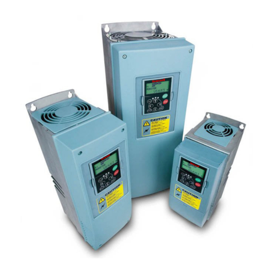
16(110) TECHNICAL DATA TECHNICAL DATA Introduction Figure 4-1 presents the block diagram of the NX frequency converter. The frequency converter mechani- cally consists of two units, the Power Unit and the Control Unit. Pictures of the mechanical assemblage on pages 54 to 62. The three-phase AC-choke (1) at the mains end together with the DC-link capacitor (2) form an LC-filter, which, again, together with the diode bridge produce the DC-voltage supply to the IGBT Inverter Bridge (3) block. - Page 18 TECHNICAL DATA 17(110) The control keypad constitutes a link between the user and the frequency converter. The control keypad is used for parameter setting, reading status data and giving control commands. It is detachable and can be operated externally and connected via a cable to the frequency converter. Instead of the control keypad, also a PC can be used to control the frequency converter if connected through a similar cable.
-
Page 19: Power Ratings
18(110) TECHNICAL DATA Power ratings 4.2.1 NX_5 – Mains voltage 380—500 V High overload = Max current IS, 2 sec/20 sec, 150% overloadability, 1 min/10 min Following continuous operation at rated output current, 150 % rated output current (IH) for 1 min, followed by a period of load current less than rated current, and of such duration that the r.m.s output current, over the duty cycle, does not exceed rated output current (IH) Low overload = Max current IS, 2 sec/20 sec, 110% overloadability, 1 min/10 min... -
Page 20: Nx_6 - Mains Voltage 525-690 V
TECHNICAL DATA 19(110) 4.2.2 NX_6 – Mains voltage 525—690 V High overload = Max current IS, 2 sec/20 sec, 150% overloadability, 1 min/10 min Following continuous operation at rated output current, 150 % rated output current (IH) for 1 min, followed by a period of load current less than rated current, and of such duration that the r.m.s output current, over the duty cycle, does not exceed rated output current (IH) Low overload = Max current IS, 2 sec/20 sec, 110% overloadability, 1 min/10 min... -
Page 21: Nx_2 - Mains Voltage 208-240 V
20(110) TECHNICAL DATA 4.2.3 NX_2 – Mains voltage 208—240 V High overload = Max current IS, 2 sec/20 sec, 150% overloadability, 1 min/10 min Following continuous operation at rated output current, 150 % rated output current (IH) for 1 min, followed by a period of load current less than rated current, and of such duration that the r.m.s output current, over the duty cycle, does not exceed rated output current (IH) Low overload = Max current IS, 2 sec/20 sec, 110% overloadability, 1 min/10 min... -
Page 22: Brake Resistor Ratings
TECHNICAL DATA 21(110) Brake resistor ratings Mains voltage 380-500 V, 50/60 Hz, 3~ Max. brake current Resistor nom Max. brake current Resistor nom. Converter type Converter type [ohm] [ohm] NX 0003 5 NX 0105 5 NX 0004 5 NX 0140 5 NX 0005 5 NX 0168 5 NX 0007 5... - Page 23 22(110) TECHNICAL DATA Mains voltage 208-240 V, 50/60 Hz, 3~ Max. brake current Resistor nom Max. brake current Resistor nom. Converter type Converter type [ohm] [ohm] NX 0004 2 NX 0061 2 NX 0007 2 NX 0075 2 NX 0008 2 NX 0088 2 NX 0011 2 NX 0114 2...
-
Page 24: Technical Data
TECHNICAL DATA 23(110) Technical data Mains Input voltage U 208…240V; 380…500V; 525…690V; –15%…+10% connection Input frequency 45…66 Hz Connection to mains Once per minute or less Starting delay 2 s (FR4 to FR8); 5 s (FR9) Motor Output voltage 0—U connection Continuous output : Ambient temperature max. - Page 25 24(110) TECHNICAL DATA Immunity Fulfils EN61800-3 (2004), first and second environment (at default Emissions Depend on EMC level. See chapters 2 and 3. settings) Safety EN 61800-5-1 (2003), CE, cUL, C-TICK; (see unit nameplate for more detailed approvals) Emissions Average noise level (cooling fan) in dB (A) FR10 FR11...
-
Page 26: Installation
INSTALLATION 25(110) INSTALLATION Mounting The frequency converter can be mounted in either vertical or horizontal position on the wall or on the back plane of a cubicle. However, if the drive is mounted in a horizontal position, it is not protected against vertically falling drops of water. - Page 27 26(110) INSTALLATION Ø H1 H2 E1Ø E2Ø* Ø fr5ip21.fh8 Figure 5-1. NX dimensions Type Dimensions [mm] ∅ E1∅ E2∅* 0004—0012 NXS2 3 x 28,3 0003—0012 NX_5 0017—0031 NXS2 2 x 37 1 x 28,3 0016—0031 NX_5 0048—0061 NXS2 0038—0061 NX_5 3 x 37 0004—0034 NX_6 0075—0114 NXS2...
- Page 28 INSTALLATION 27(110) H1 H2 Ø fr5ip21kaulus.fh8 Figure 5-2. NX dimensions, FR4 to FR6; Flange mounting Type Dimensions [mm] ∅ 0004—0012 NXS2 0003—0012 NX_5 0017—0031 NXS2 0016—0031 NX_5 0048—0061 NXS2 0038—0061 NX_5 0004—0034 NX_6 Table 5-2. Dimensions for different frequency converter types FR4 to FR6, flange mounting...
- Page 29 28(110) INSTALLATION Ø fr6aukko.fh8 Figure 5-3. The opening needed for the flange mounting, FR4 to FR6 Type Dimensions [mm] ∅ 0004—0012 NXS2 – – 0003—0012 NX_5 0017—0031 NXS2 – – 0016—0031 NX_5 0048—0061 NXS2 0038—0061 NX_5 0004—0034 NX_6 Table 5-3. Dimensions for the opening for flange mounting, FR4 to FR6...
- Page 30 INSTALLATION 29(110) fr7kaulusip21.fh8 Figure 5-4. NX dimensions, FR7 and FR8, flange mounting Type Dimensions [mm] ∅ H6 H7 0075—0114 NXS2 0072—0105 NX_5 188.5 188.5 23 20 0041—0052 NX_6 0140—0205 NXS2 0140—0205 NX_5 832* – 43 57 0062—0100 NX_6 Table 5-4. Dimensions for different frequency converter types FR7 and FR8, flange mounting *Brake resistor terminal box (202.5 mm) not included, see page 60...
- Page 31 30(110) INSTALLATION W1 W2 Ø fr7aukko.fh8 Figure 5-5. The opening needed for the flange mounting, FR7 Type Dimensions [mm] ∅ 0075—0114 NXS2 0072—0105 NX_5 188.5 188.5 34.5 0041—0052 NX_6 Table 5-5. Dimensions for the opening for flange mounting, FR7 Bottom edge of the opening Figure 5-6.
- Page 32 INSTALLATION 31(110) Ø fr9ip21.fh8 Figure 5-7. The dimensions NX, FR9 Type Dimensions [mm] ∅ W1 W2 W3 W4 H6 D1 0261—0300 NXS2 0261—0300 NX_5 480 400 165 1120 721 205 16 188 362 340 285 21 1150* 0125—0208 NX_6 Table 5-7. The dimensions NX, FR9 *Brake resistor terminal box (H6) not included, see page 60.
- Page 33 32(110) INSTALLATION Ø Opening fr9collar.fh8 Figure 5-8. NX dimensions. FR9 flange mounting Type Dimensions [mm] ∅ 0261-0300 NXS2 0261-0300 NX_5 1312 1150 0125-0208 NX_6 Table 5-8. NX dimensions. FR9 flange-mounted...
- Page 34 INSTALLATION 33(110) Type plate Warning plate Figure 5-9. NX dimensions, FR10 and FR11 (floorstanding units) Type Dimensions [mm] W1 W2 W3 W4 H4 H5 D1 0385…0520 NX_5 595 291 131 15 2018 1900 1435 512 40 602 0261…0416 NX_6 0590…0730 NX_5 794 390 230 15 2018 1900 1435 512 40 602 0460…0590 NX_6...
- Page 35 34(110) INSTALLATION Ty pe plate Detail Y, 1:5 Warning plate Detail X, 1:5 1197 Figure 5-10. NX dimensions, FR12 (floorstanding units)
-
Page 36: Cooling
INSTALLATION 35(110) Cooling Enough free space shall be left around the frequency converter to ensure sufficient air circulation, cooling as well as maintenance. You will find the required dimensions for free space in the tables below. If several units are mounted above each other the required free space equals C + D (see figure below). Moreover, the outlet air used for cooling by the lower unit must be directed away from the air intake of the upper unit. - Page 37 36(110) INSTALLATION Type Cooling air required [m 0004—0012 NXS2 0003—0012 NX_5 0017—0031 NXS2 0016—0031 NX_5 0004—0013 NX_6 0048—0061 NXS2 0038—0061 NX_5 0018—0034 NX_6 0075—0114 NXS2 0072—0105 NX_5 0041—0052 NX_6 0140—0205 NXS2 0140—0205 NX_5 0062—0100 NX_6 0261—0300 NXS2 0261—0300 NX_5 1300 0125—0208 NX_6 Table 5-11.
-
Page 38: Standalone Units (Fr10 To Fr12)
INSTALLATION 37(110) 5.2.2 Standalone units (FR10 to FR12) Type Dimensions [mm] 0385—0520 NX_5 0261—0416 NX_6 0590—0730 NX_5 0460—0590 NX_6 0820—1030 NX_5 0650—0820 NX_6 A = Minimum distance to the side walls or adjacent components. B = Minimum distance from the top of the cabinet C = Free space underneath the module D = Minimum distance between the phase cables... - Page 39 38(110) INSTALLATION Mounting space dimensions [mm] Table 5-12. Mounting space dimensions Type Cooling air required 0385—0520 5 2600 0261—0416 6 0650—0730 5 3900 0460—0590 6 0820—1030 5 5200 0650—0820 6 Table 5-13. Required cooling air Figure 5-12. Cabinet installation space...
-
Page 40: Power Losses
INSTALLATION 39(110) Power losses 5.3.1 Power losses as function of switching frequency If the operator wants to raise the switching frequency of the drive for some reason (typically e.g. in order to reduce the motor noise), this inevitably affects the power losses and cooling requirements according to the graphs below. - Page 41 40(110) INSTALLATION 1400,00 1200,00 1000,00 800,00 600,00 400,00 200,00 0,00 0,00 2,00 4,00 6,00 8,00 10,00 12,00 14,00 16,00 Switching frequency [kHz] 0038NX5 400V 0038NX5 500V 0045NX5 400V 0045NX5 500V 0061NX5 400V 0061NX5 500V Figure 5-15. Power loss as function of switching frequency; 0038…0061NX5 2500,00 2000,00 1500,00...
- Page 42 INSTALLATION 41(110) 4000,00 3500,00 3000,00 2500,00 2000,00 1500,00 1000,00 500,00 0,00 0,00 2,00 4,00 6,00 8,00 10,00 12,00 Switching frequency [kHz] 0140NX5 400V 0140NX5 500V 0168NX5 400V 0168NX5 500V 0205NX5 400V 0205NX5 500V Figure 5-17. Power loss as function of switching frequency; 0140…0205NX5 4000,00 3500,00 3000,00...
- Page 43 42(110) INSTALLATION 8000,00 7000,00 6000,00 5000,00 0385NX 400V 0385NX 500V 0460NX 400V 4000,00 0460NX 500V 0520NX 400V 0520NX 500V 3000,00 2000,00 1000,00 0,00 Switching frequency [kHz] Figure 5-19. Power loss as function of switching frequency; 0385…0520 NX_5...
-
Page 44: Cabling And Connections
CABLING AND CONNECTIONS 43(110) CABLING AND CONNECTIONS Power unit 6.1.1 Power connections 6.1.1.1 Mains and motor cables The mains cables are connected to terminals L1, L2 and L3 and the motor cables to terminals marked with U, V and W. A cable entry gland should be used when installing the motor cable at both ends in order to reach the EMC levels. -
Page 45: Dc Supply And Brake Resistor Cables
44(110) CABLING AND CONNECTIONS 6.1.1.2 DC supply and brake resistor cables Frequency converters are equipped with terminals for the DC supply and an optional external brake resistor. These terminals are marked with B–, B+/R+ and R–. The DC bus connection is made to terminals B–... -
Page 46: Cable And Fuse Sizes, Nx_6, Fr6 To Fr9
CABLING AND CONNECTIONS 45(110) 6.1.1.5 Cable and fuse sizes, NX_6, FR6 to FR9 The table below shows typical cable sizes and types that can be used with the converter. The final selection should be made according to local regulations, cable installation conditions and cable specification. -
Page 47: Cable And Fuse Sizes, Nx_5, Fr10 To Fr12
46(110) CABLING AND CONNECTIONS 6.1.1.6 Cable and fuse sizes, NX_5, FR10 to FR12 The table below shows typical cable sizes and types that can be used with the converter. The final selection should be made according to local regulations, cable installation conditions and cable specification. -
Page 48: Understanding The Power Unit Topology
CABLING AND CONNECTIONS 47(110) 6.1.2 Understanding the power unit topology Figure 6-1 shows the principles for mains and motor connections of the basic 6-pulse drive in frame sizes FR4 to FR12. Note! Min cable length 5m FR4-9/FR10 FR11* FR12 Single input Double input* Double input Single output... -
Page 49: Changing The Emc Protection Class
48(110) CABLING AND CONNECTIONS 6.1.3 Changing the EMC protection class The EMC protection level of NX frequency converters can be changed from class H to class T (and from class L to T in NX_6 FR6) with a simple procedure presented in the following figures. Note! After having performed the change check EMC Level modified on the sticker included in the NX delivery (see below) and note the date. - Page 50 CABLING AND CONNECTIONS 49(110) FR7: Remove this screw and replace with plastic screw M4 Remove this screw Figure 6-4. Changing of EMC protection class, FR7 NOTE! Only an authorized service person may change the EMC protection class of NX, FR8 and FR9.
-
Page 51: Mounting Of Cable Accessories
50(110) CABLING AND CONNECTIONS 6.1.4 Mounting of cable accessories Enclosed to your NX frequency converter you have received a plastic bag containing components that are needed for the installation of the mains and motor cables in the frequency converter. Figure 6-5. Cable accessories Components: Grounding terminals (FR4, FR5/MF4, MF5) (2) Cable clamps (3) - Page 52 CABLING AND CONNECTIONS 51(110)
-
Page 53: Installation Instructions
52(110) CABLING AND CONNECTIONS 6.1.5 Installation instructions Before starting the installation, check that none of the components of the frequency converter is live. Place the motor cables sufficiently far from other cables: Avoid placing the motor cables in long parallel lines with other cables If the motor cables runs in parallel with other cables, note the minimum distances between the motor cables and other cables given in table below. -
Page 54: Stripping Lengths Of Motor And Mains Cables
CABLING AND CONNECTIONS 53(110) 6.1.5.1 Stripping lengths of motor and mains cables Earth Earth conductor conductor MAIN S MOTOR nk6141.fh8 Figure 6-6. Stripping of cables Frame 0140 0168—0205 Table 6-6. Cables stripping lengths [mm]... -
Page 55: Nx Frames And Installation Of Cables
54(110) CABLING AND CONNECTIONS 6.1.5.2 NX frames and installation of cables Note: In case you want to connect an external brake resistor, see separate Brake Resistor Manual. See also Chapter 'Internal brake resistor connection (P6.7.1)' on page 98 in this manual. Figure 6-7. - Page 56 CABLING AND CONNECTIONS 55(110) Figure 6-9. Additional grounding connector for FR4...
- Page 57 56(110) CABLING AND CONNECTIONS Figure 6-10. NX, FR5. Brake resistor DC terminals terminals Earth terminals Mains cable Motor cable Figure 6-11. Cable installation in NX, FR5 NOTE: See chapter 1.3.
- Page 58 CABLING AND CONNECTIONS 57(110) Figure 6-12. NX, FR6. Brake resistor terminals terminals Brake resistor terminals Earth terminals Earth terminals Motor cable Mains cable Mains cable Motor cable Figure 6-13. Cable installation in NX, FR6 NOTE: See chapter 1.3.
- Page 59 58(110) CABLING AND CONNECTIONS Figure 6-14. NX, FR7. Brake resistor terminals terminals Earth terminals Mains cable Motor cable Figure 6-15. Cable installation in NX, FR7 NOTE: See chapter 1.3.
- Page 60 CABLING AND CONNECTIONS 59(110) Figure 6-16. NX, FR8 (with optional DC/brake resistor connection box on top)
- Page 61 60(110) CABLING AND CONNECTIONS Motor cable Mains cable Earth terminal Figure 6-17. Cable installation in NX, FR8 DC terminals Brake resistor terminals Figure 6-18. Brake resistor terminal box on top of FR8;...
- Page 62 CABLING AND CONNECTIONS 61(110) Figure 6-19. NX, FR9 Motor cables Mains cable Earth terminals Figure 6-20. Cable installation in NX, FR9...
- Page 63 62(110) CABLING AND CONNECTIONS B– B+/R+ R– Figure 6-21. DC and brake resistor terminals on FR9; DC terminals marked with B– and B+, brake resistor terminals marked with R+ and R–...
- Page 64 CABLING AND CONNECTIONS 63(110) Figure 6-22. Example of NXP standalone drives (FR11) Note: More information on cabling for frames FR10 and greater you will find in the NXP/C User’s Manual.
-
Page 65: Cable Selection And Unit Installation In Accordance With The Ul Standards
64(110) CABLING AND CONNECTIONS 6.1.6 Cable selection and unit installation in accordance with the UL standards To meet the UL (Underwriters Laboratories) regulations, use a UL-approved copper cable with a minimum ° heat-resistance of +60/75 C. Use Class 1 wire only. The units are suitable for use on a circuit capable of delivering not more than 100,000 rms symmetrical amperes, 600V maximum. -
Page 66: Control Unit
CABLING AND CONNECTIONS 65(110) Control unit The control unit of the frequency converter consists roughly of the control board and additional boards (see Figure 6-23 and Figure 6-24) connected to the five slot connectors (A to E) of the control board. The control board is connected to the power unit through a D-connector (1) or fibre optic cables (FR9). -
Page 67: Control Connections
66(110) CABLING AND CONNECTIONS 6.2.1 Control connections The basic control connections for boards A1 and A2/A3 are shown in Chapter 6.2.2. The signal descriptions are presented in the All in One Application Manual. +10Vref Reference AI1+ (voltage) AI2+ Reference AI2- (current) 24Vout DIN1... -
Page 68: Control Cables
CABLING AND CONNECTIONS 67(110) 6.2.1.1 Control cables The control cables shall be at least 0.5 mm screened multicore cables, see Table 6-1. The maximum terminal wire size is 2.5 mm for the relay terminals and 1.5 mm for other terminals. Find the tightening torques of the option board terminals in Table below. -
Page 69: Control Terminal Signals
68(110) CABLING AND CONNECTIONS 6.2.2 Control terminal signals OPT-A1 Terminal Signal Technical information +10 Vref Reference voltage Maximum current 10 mA AI1+ Analogue input, Selection V or mA with jumper block X1 (see page 71): voltage or current Default: 0– +10V (Ri = 200 kΩ) (-10V…..+10V Joy-stick control, selected with a jumper) 0–... -
Page 70: Digital Input Signal Inversions
CABLING AND CONNECTIONS 69(110) OPT-A2 Terminal Signal Technical information RO1/1 Relay output 1 Switching capacity 24VDC/8A 250VAC/8A RO1/2 125VDC/0.4A RO1/3 Min.switching load 5V/10mA RO2/1 Relay output 2 Switching capacity 24VDC/8A 250VAC/8A RO2/2 125VDC/0.4A RO2/3 Min.switching load 5V/10mA Table 6-10. Control I/O terminal signals on basic relay board OPT-A2 OPT-A3 Terminal Signal... -
Page 71: Jumper Selections On The Opt-A1 Basic Board
70(110) CABLING AND CONNECTIONS 6.2.2.2 Jumper selections on the OPT-A1 basic board The user is able to customise the functions of the frequency converter to better suit his needs by selecting certain positions for the jumpers on the OPT-A1 board. The positions of the jumpers determine the signal type of analogue and digital inputs. - Page 72 CABLING AND CONNECTIONS 71(110) Jum per block X 1 : Jum per block X 2 : AI1 m ode AI2 m ode AI1 mode: 0...20mA; Current input AI2 mode: 0...20mA; Current input AI1 mode: Voltage input; 0...10V AI2 mode: Voltage input; 0...10V AI1 mode: Voltage input;...
-
Page 73: Control Keypad
72(110) CONTROL KEYPAD CONTROL KEYPAD The control keypad is the link between the frequency converter and the user. The NX control keypad features an alphanumeric display with seven indicators for the Run status (RUN, , READY, STOP, ALARM, FAULT) and three indicators for the control place (I/O term/ Keypad/BusComm). There are also three Status Indicator LEDs (green - green - red), see Status LEDs (green –... -
Page 74: Control Place Indications
CONTROL KEYPAD 73(110) 7.1.2 Control place indications (See control keypad) The symbols I/O term, Keypad and Bus/Comm (see Figure 7-1) indicate the choice of control place made in the Keypad control menu (M3) (see chapter 7.3.3). I/O term = I/O terminals are the selected control place; i.e. START/STOP commands or reference values etc. -
Page 75: Keypad Push-Buttons
74(110) CONTROL KEYPAD Keypad push-buttons The alphanumeric control keypad features 9 push-buttons that are used for the control of the frequency converter (and motor), parameter setting and value monitoring. Figure 7-2. Keypad push-buttons 7.2.1 Button descriptions reset This button is used to reset active faults (see Chapter 7.3.4). select This button is used to switch between two latest displays. -
Page 76: Navigation On The Control Keypad
CONTROL KEYPAD 75(110) Navigation on the control keypad The data on the control keypad are arranged in menus and submenus. The menus are used for example for the display and editing of measurement and control signals, parameter settings (chapter 7.3.2), reference values and fault displays (chapter 7.3.4). - Page 77 76(110) CONTROL KEYPAD READY R EADY R EADY I/Oterm I/Ote rm I/Oterm Expander boards A:NXOPTA1 Parameters G1 G5 G1 G1 P1 P3 STOP R EADY STOP R EADY Change I/Ote rm I/Ote rm enter value System Menu Language S1 S9 English Browse READY...
-
Page 78: Monitoring Menu (M1)
CONTROL KEYPAD 77(110) 7.3.1 Monitoring menu (M1) You can enter the Monitoring menu from the Main menu by pushing the Menu button right when the location indication M1 is visible on the first line of the display. How to browse through the monitored values is presented in Figure 7-4. -
Page 79: Parameter Menu (M2)
78(110) CONTROL KEYPAD 7.3.2 Parameter menu (M2) Parameters are the way of conveying the commands of the user to the frequency converter. The parameter values can be edited by entering the Parameter Menu from the Main Menu when the location indication M2 is visible on the first line of the display. -
Page 80: Keypad Control Menu (M3)
CONTROL KEYPAD 79(110) 7.3.3 Keypad control menu (M3) In the Keypad Controls Menu, you can choose the control place, edit the frequency reference and change the direction of the motor. Enter the submenu level with the Menu button right. Code Parameter Unit Default... -
Page 81: Keypad Reference
80(110) CONTROL KEYPAD 7.3.3.2 Keypad reference The keypad reference submenu (P3.2) displays and allows the operator to edit the frequency reference. The changes will take place immediately. This reference value will not, however, influence the rotation speed of the motor unless the keypad has been selected as source of reference. NOTE: The maximum difference in RUN mode between the output frequency and the keypad reference is 6 Hz. -
Page 82: Active Faults Menu (M4)
CONTROL KEYPAD 81(110) 7.3.4 Active faults menu (M4) The Active faults menu can be entered from the Main menu by pushing the Menu button right when the location indication M4 is visible on the first line of the keypad display. When a fault brings the frequency converter to a stop, the location indication F1, the fault code, a short description of the fault and the fault type symbol (see Chapter 7.3.4.1) will appear on the display. -
Page 83: Fault Types
82(110) CONTROL KEYPAD 7.3.4.1 Fault types In the NX frequency converter, there are four different types of faults. These types differ from each other on the basis of the subsequent behaviour of the drive. See Table 7-3. I/Oterm Operation hours 34:21:05 STOP FAULT... -
Page 84: Fault Codes
CONTROL KEYPAD 83(110) 7.3.4.2 Fault codes The fault codes, their causes and correcting actions are presented in the table below. The shadowed faults are A faults only. The items written in white on black background present faults for which you can program different responses in the application. - Page 85 84(110) CONTROL KEYPAD Fault Fault Possible cause Correcting measures code Undervoltage DC-link voltage is under the voltage limits In case of temporary supply voltage defined. break reset the fault and restart the − frequency converter. Check the supply most probable cause: too low a voltage.
- Page 86 CONTROL KEYPAD 85(110) Fault Fault Possible cause Correcting measures code IGBT temperature IGBT Inverter Bridge overtemperature Check loading. (hardware) protection has detected too high a short Check motor size. term overload current Make identification run. Fan cooling Cooling fan of the frequency converter Contact the distributor near to you.
- Page 87 86(110) CONTROL KEYPAD Fault Fault Possible cause Correcting measures code Fieldbus fault The data connection between the fieldbus Check installation. Master and the fieldbus board is broken If installation is correct contact the nearest distributor. Slot fault Defective option board or slot Check board and slot.
-
Page 88: Fault Time Data Record
CONTROL KEYPAD 87(110) 7.3.4.3 Fault time data record When a fault occurs the information described above in 7.3.4 is displayed. By pushing the Menu button right here you will enter the Fault time data record menu indicated by T.1 T.13. In this menu, some selected important data valid at the time of the fault are recorded. -
Page 89: Fault History Menu (M5)
88(110) CONTROL KEYPAD 7.3.5 Fault history menu (M5) The Fault history menu can be entered from the Main menu by pushing the Menu button right when the location indication M5 is visible on the first line of the keypad display. Find the fault codes in Table 7-4. All faults are stored in the Fault history menu in which you can browse through them using the Browser buttons. -
Page 90: System Menu (M6)
CONTROL KEYPAD 89(110) 7.3.6 System menu (M6) The System menu can be entered from the main menu by pushing the Menu button right when the location indication M6 is visible on the display. The controls associated with the general use of the frequency converter, such as application selection, customised parameter sets or information about the hardware and software are located under the System menu. - Page 91 90(110) CONTROL KEYPAD Continuous P6.7.2 Fan control Continuous Temperature HMI acknowledg. P6.7.3 5000 timeout HMI number of P6.7.4 retries System S6.8 information S6.8.1 Total counters C6.8.1.1 MWh counter Power On day C6.8.1.2 counter Power On hours C6.8.1.3 hh:mm:ss counter S6.8.2 Trip counters T6.8.2.1 MWh counter...
-
Page 92: Language Selection
CONTROL KEYPAD 91(110) 7.3.6.1 Language selection The HMI control keypad offers the user the possibility to control the frequency converter through the keypad in the language of your choice. Locate the language selection page under the System menu. Its location indication is S6.1. Press the Menu button right once to enter the edit mode. -
Page 93: Copy Parameters
92(110) CONTROL KEYPAD STOP READY STOP READY I/Oterm I/Oterm Application System Menu Standard S1 S11 STOP READY STOP READY I/Oterm I/Oterm Application Application enter Multi-step Standard Figure 7-10. Change of application 7.3.6.3 Copy parameters The parameter copy function is used when the operator wants to copy one or all parameter groups from one drive to another or to store parameter sets in the internal memory of the converter. - Page 94 CONTROL KEYPAD 93(110) Upload parameters to keypad (To keypad, S6.3.2) This function uploads all existing parameter groups to the keypad provided that the drive is stopped. Enter the To keypad page (S6.3.2) from the Parameter copy menu. Push the Menu button right to enter the edit mode.
-
Page 95: Parameter Comparison
94(110) CONTROL KEYPAD 7.3.6.4 Parameter comparison In the Parameter comparison submenu (S6.4), you can compare the actual parameter values to the values of your customised parameter sets and those loaded to the control keypad. The comparison is performed by pushing the Menu button right when in the Compare parameters submenu. -
Page 96: Security
CONTROL KEYPAD 95(110) 7.3.6.5 Security NOTE: The Security submenu is protected with a password. Store the password in a safe place! Password (S6.5.1) The application selection can be protected against unauthorised changes with the Password function (S6.5.1). By default, the password function is not in use. If you want to activate the function, enter the edit mode by pushing the Menu button right. -
Page 97: Keypad Settings
Figure 7-16. Activation of Start-up wizard Multimonitoring items (P6.5.4) Honeywell alpha-numeric keypad features a display where you can monitor even three actual values at the same time (see chapter 7.3.1 and chapter Monitoring values in the manual of the application you are using). - Page 98 CONTROL KEYPAD 97(110) Default page (P6.6.1) Here you can set the location (page) to which the display automatically moves as the Timeout time (see below) has expired or as the power is switched on to the keypad. If the Default Page value is 0 the function is not activated, i.e. the last displayed page remains on the keypad display.
-
Page 99: Hardware Settings
98(110) CONTROL KEYPAD 7.3.6.7 Hardware settings NOTE: The Hardware settings submenu is protected with a password (see chapter Password (S6.5.1)). Store the password in a safe place! In the Hardware settings submenu (S6.7) under the System menu you can further control some functions of the hardware in your frequency converter. - Page 100 CONTROL KEYPAD 99(110) Enter the edit mode by pushing the Menu button right. The present mode shown starts to blink. Use the Browser buttons to change the fan mode. Accept the change with the Enter button or return to the previous level with the Menu button left.
-
Page 101: System Info
100(110) CONTROL KEYPAD Number of retries to receive HMI acknowledgement (P6.7.4) With this parameter you can set the number of times the drive will try receive acknowledgement if this does not succeed within the acknowledgement time (P6.7.3) or if the received acknowledgement is faulty. Enter the edit mode by pushing the Menu button right. - Page 102 CONTROL KEYPAD 101(110) STOP READY READY STOP READY Clr Optime cntr Clr Optime cntr Trip counters Not reset Not reset T1 T5 STOP READY STOP READY STOP READY Clr Optime cntr Clr Optime cntr Clr Optime cntr enter Reset Reset Not reset Figure 7-24.
- Page 103 102(110) CONTROL KEYPAD In the Applications information page, push the Menu button right to enter the Application pages of which there are as many as there are applications loaded into the frequency converter. Locate the application you want information about with the Browser buttons and then enter the Information pages with the Menu button right.
-
Page 104: Expander Board Menu (M7)
CONTROL KEYPAD 103(110) 7.3.7 Expander board menu (M7) The Expander board menu makes it possible for the user 1) to see what expander boards are connected to the control board and 2) to reach and edit the parameters associated with the expander board. Enter the following menu level (G#) with the Menu button right. -
Page 105: Commissioning
104(110) COMMISSIONING COMMISSIONING Safety Before commissioning, note the following directions and warnings: Internal components and circuit boards of the frequency converter (ex- cept for the galvanically isolated I/O terminals) are live when NX is connected to mains potential. Coming into contact with this voltage is extremely dangerous and may cause death or severe injury. - Page 106 COMMISSIONING 105(110) Set the parameters of group 1 (See Application Manual) according to the requirements of your application. At least the following parameters should be set: motor nominal voltage motor nominal frequency motor nominal speed motor nominal current You will find the values needed for the parameters on the motor rating plate. Perform run test without motor Perform either Test A or Test B: A Controls from the I/O terminals:...
- Page 107 106(110) COMMISSIONING Connect the motor to the process (if the startup test was run without the motor being connected) a) Before running the tests, make sure that this can be done safely. b) Inform your co-workers of the tests. c) Repeat test 8A or 8...
-
Page 108: Fault Tracing
FAULT TRACING 107(110) FAULT TRACING When a fault is detected by the frequency converter control electronics, the drive is stopped and the symbol F together with the ordinal number of the fault, the fault code and a short fault description appear on the display. The fault can be reset with the Reset button on the control keypad or via the I/O terminal. - Page 109 108(110) FAULT TRACING Fault Fault Possible cause Correcting measures code Undervoltage DC-link voltage is under the voltage limits In case of temporary supply voltage defined. break reset the fault and restart the − frequency converter. Check the supply most probable cause: too low a voltage.
- Page 110 FAULT TRACING 109(110) Fault Fault Possible cause Correcting measures code IGBT temperature IGBT Inverter Bridge overtemperature Check loading. (hardware) protection has detected too high a short Check motor size. term overload current Make identification run. Fan cooling Cooling fan of the frequency converter Contact the distributor near to you.
- Page 111 110(110) FAULT TRACING Fault Fault Possible cause Correcting measures code Fieldbus fault The data connection between the fieldbus Check installation. Master and the fieldbus board is broken If installation is correct contact the nearest distributor. Slot fault Defective option board or slot Check board and slot.
- Page 112 NX QUICK HELP Start-up wizard The Start Up Wizard is activated when the power to the drive is turned on for the first time, or if the Start Up Wizard is activated from the System menu (P6.5.3) AND the power is turned OFF and back ON.
- Page 113 Monitoring values Faults and fault codes Code Signal name Unit Fault Fault code V1.1 Output frequency Overcurrent V1.2 Frequency reference Overvoltage V1.3 Motor speed Earth fault V1.4 Motor current Charging switch Emergency stop V1.5 Motor torque Saturation trip V1.6 Motor power System fault V1.7 Motor voltage...
- Page 114 Actual value special display The Actual value special display parameters are used to convert and display the actual value signal in a form more informative to the user. The Actual value special display parameters are available in PID Control Application and Pump and Fan Control Application: Par ID Parameter name...
- Page 115 Selection of language 1. Find the System Menu (M6) 2. Enter the Language selection page (S6.1). 3. Push the Menu button right to make the name of language blink. 4. Browse through the languages with the Browser buttons and select another language with the Enter button.
- Page 116 Control panel menus READY R EADY R EADY I/Oterm I/Ote rm I/Oterm Expander boards A:NXOPTA1 Parameters G1 G5 G1 G1 P1 P3 STOP R EADY STOP R EADY Change I/Ote rm I/Ote rm enter value System Menu Language S1 S9 English Browse READY...
- Page 117 Keypad shortcuts Quick activation of keypad contol (I/O term) (Bus/Comm) If you have selected either the I/O terminal control or the fieldbus control as the active control place but wish to take over the control from these to the keypad, this can be done in two different ways. A.