
Related Manuals for Honeywell EK280


Summary of Contents for Honeywell EK280
- Page 1 Volume Conversion Device EK280 Operating Instructions 73021209 Issue date 2019-01 (f) From software version 2.51...
- Page 2 Exclusion of liability The information contained in this document is the property of Honeywell. The following information may only be used for its intended purpose. This document or its contents must not be copied, published or made accessible to a third party in full or in part without the express consent of Elster GmbH.
-
Page 3: Table Of Contents
3.3.1 Battery power supply for the basic device .......... 23 3.3.2 External power supply ................ 23 3.3.3 Buffer batteries for the integrated modem .......... 23 Power supply for the EK280 with Power over Ethernet (PoE) ..23 Pressure sensor ................24 3.5.1 CT30 Type Pressure Sensor .............. 24 3.5.2 Pressure Sensor Type 17002 ............ - Page 4 5.2.5 Connecting the power supply ............43 5.2.6 Connect outputs of the EK280 ............45 5.2.7 Earthing the EK280 housing.............. 46 5.2.8 Earthing the cable connections of the EK280........47 5.2.9 Additional measures for installation in zone 2 ........47 Putting into operation ..............48 5.3.1 Configuration of measurement parameters ........
- Page 5 Operating personnel ..............62 6.2.1 Instructed personnel................62 6.2.2 Qualified personnel ................62 6.2.3 Calibration officers ................63 Basic principles ................63 6.3.1 Display ....................64 6.3.2 Button functions ................. 65 6.3.3 Data recall, display navigation ............66 6.3.4 Meaning of status symbols ..............67 6.3.5 Error messages when entering values ..........
-
Page 7: General
The data and material properties indicated serve as reference values. These must be verified on a case-by-case basis and adjusted as necessary. The EK280 Application Manual is available for you at (→ „Docuthek“) for the commissioning of the www.ek280.de various communication and device applications. -
Page 8: Customer Service And Repairs
+49 (0) 61 34 / 605-0 – Fax: +49 (0) 61 34 / 605-390 – E-mail: [email protected] 1.3.2 Technical Assistance Center (TAC) Our Technical Support (TAC Technical Assistance Center) is at your disposal in case of faults: – Phone: +49 (0) 6134 / 605-123 –... -
Page 9: Tips And Recommendations
General … indicates dangers resulting from electrical current. A non-compliance of the safety information poses a risk of serious or life-threatening injuries. CAUTION! ... indicates a potentially dangerous situation which, if not avoided, could lead to material damage. 1.4.2 Tips and recommendations …... -
Page 10: Copyright Protection
The free "enSuite" program also belongs to the accessories for the EK280 and is available under www.elster-instromet.com. This can be used to program the EK280 volume conversion device via its data interfaces to perform advanced applications. -
Page 11: Storage
General found under www.elster-instromet.com and in the "Assembly, Connection and Putting into Operation" chapter. Storage CAUTION! Exceeding or falling below the valid temperature range for the batteries may impair performance. If the valid temperature range of the batteries during storage of the device is exceeded or fallen below, the performance of the batteries may be impaired. -
Page 12: Safety
– Before installing the device in zone 0, 1, please check that the EK280 is suitable for use in zone 0, 1. – The EK280 should only be operated in zone 0, 1, if category "II 1 G" or "II 2 G" have been marked on the ATEX label. - Page 13 Operating the EK280 in zone 0, 1 and connecting devices which are not certified as "associated equipment" present a risk of explosion. Therefore: – When using the EK280 in zone 0, 1, it should only be connected to certified associated equipment as per the ATEX Product Directive 94/9/EC.
- Page 14 Safety – All of those persons who are charged performing works on or with the device, must have read and understood the manual before commencing such works. This shall also apply if the person in question has already worked with the same or a similar device or has been trained by the manufacturer.
-
Page 15: Intended Use
This device is solely designed and constructed for the intended use described below. The volume conversion device EK280 is used to convert the gas volume read from a gas pipe under measurement conditions, into base conditions, as well as to allocate the measured quantities to tariffs. -
Page 16: Personnel
Safety Personnel WARNING! Risk of injury to unqualified personnel. Improper use of the device may lead to significant personal injury or material damage. Therefore: – All works should solely be carried out by qualified personnel. The following qualifications are used in the manual to denote different areas of responsibility: –... -
Page 17: Personal Protective Equipment
Safety – Electricians who, on the basis of their specialist training, knowledge and experience, as well as their awareness of the relevant standards and regulations, are in a position to perform the works on electrical installations and to independently identify and prevent possible risks. The electrician will be specially trained in the respective area and will be familiar with the relevant standards and regulations. -
Page 18: Specific Risks
Safety Specific risks The residual risks arising from the risk assessment will be listed below. Please observe the safety and warning information specified in the following chapters to reduce risks to health and to prevent dangerous situations from arising. WARNING! Misuse of batteries may present a risk of injury. -
Page 19: Environmental Protection
Safety Environmental protection CAUTION! Environmentally hazardous substances! If environmentally hazardous substances are handled incorrectly this may cause significant damage to the environment, particularly if they are improperly disposed of. Therefore: – The instructions below should be observed at all times. –... -
Page 20: Technical Data
Technical data necessary. – The operator must clearly regulate and define responsibilities for the assembly, connection, putting into operation, and maintenance of the device. – The operator must ensure that all employees who use the device have read and understood this manual. Furthermore, the operator must provide training to personnel at regular intervals and inform them of the potential risks. -
Page 21: Dimensions
Technical data 3.1.1 Dimensions... -
Page 22: Power Supply For Ek280 Without Integrated Power Supply Unit
Technical data Power supply for EK280 without integrated power supply unit 3.2.1 Battery power supply for the basic device Data Value Unit Voltage General nominal capacity 16.5 Usable capacity 13.0 Minimum number of batteries required units Minimum operating life (at standard... -
Page 23: Power Supply For Ek280 With Integrated Power Supply Unit
Power supply for the EK280 with Power over Ethernet (PoE) If the EK280 is equipped with an Ethernet module and if the Ethernet network (or a switch) provides the Power over Ethernet function, the EK280 can be supplied with power from the Ethernet module. An integrated power supply is not required. -
Page 24: Pressure Sensor
Technical data Pressure sensor 3.5.1 CT30 Type Pressure Sensor Data Value Unit External thread M12 x 1.5 Usable thread length approx. 10 3.5.1.1 Absolute pressure ranges Measuring range Overload capacity 0.7 ... 2 bar abs. 18 bar abs. 0.8 ... 5 bar abs. 25 bar abs. -
Page 25: Pressure Sensor Type 17002
Technical data 3.5.2 Pressure Sensor Type 17002 Data Value Unit External thread (internal model) M12 x 1.5 Usable thread length (internal model) approx. 10 Measuring range Overload capacity … 7 bar abs. 10 bar abs. The pressure sensor is available as both an external and internal model. -
Page 26: Hf Pulse Inputs (High Frequency)
Technical data Data Value Unit Open-circuit voltage U MΩ Internal resistance R μA Short circuit current I ▪ Resistance R kΩ Switch point "ON": max. ▪ Voltage U max. MΩ ▪ Resistance R Switch point "OFF": min. ▪ Voltage U min. -
Page 27: Digital Outputs
Technical data Digital outputs The digital outputs DA2 and DA3 can be configured as low or high frequency pulse or signal outputs. The digital outputs DA1 and DA4 can exclusively be configured as low frequency pulse or signal outputs. 3.8.1 Nominal data Data Value Unit... -
Page 28: Interfaces
Technical data Interfaces 3.9.1 Serial optical interface Data Value Unit Baud rate 9600 Format 1 start bit, 1 parity bit, 1 stop bit The baud rate of the serial optical interface is adjustable to 19200 Bd. However, the function with this baud rate depends among others also from the optical read out head and therefore cannot be guaranteed. -
Page 29: Ethernet Adapter
Instruments Directive (MID). The label is placed on the front panel of the device (see Construction and Function chapter). 3.11.1 Type label of the volume corrector The type label of the EK280 relating to its function as a volume corrector, contains the following information: 1 Type designation EK280... -
Page 30: Atex Marking
Technical data 3.11.2 ATEX marking The plate for the "Ex" marking of the EK280 is located on the top panel of the device housing. 3.11.2.1 Zone 0, 1 (without integrated power supply unit) ELSTER GmbH II 1 G 55252 Mainz- Kastel... -
Page 31: Device Software Identification
Technical data 3.11.3 Device software identification – Move the cursor using the arrow keys to the "Serv." register and to the values "Vers" (device software version) and "Chk" (checksum) via the following path: Serv. Identification Volume Converter "Vers"... -
Page 32: Construction And Function
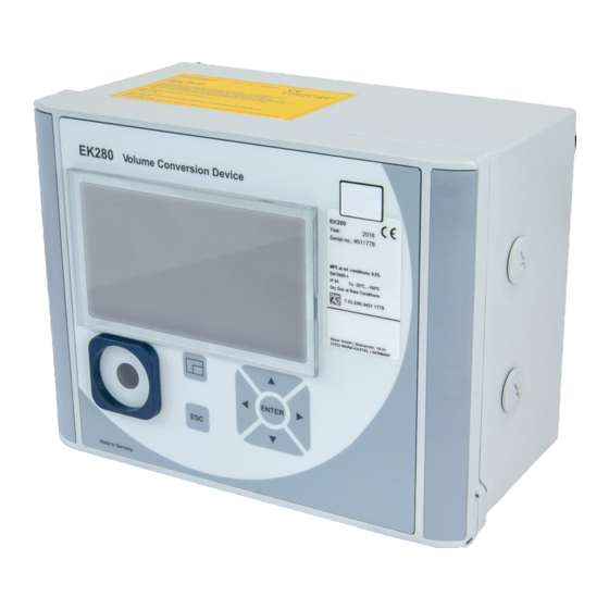
Construction and Function Construction and Function External view 1 Display 2 Cable bushings for the connection of additional components Identification label 3 Optical interface 4 Escape button "ESC" 5 Enter button "ENTER" 6 Function key Instromet 7 Arrow keys , , , 8 Pressure sensor 9 Cable bushing Temperature sensor... -
Page 33: Short Description
Construction and Function Short description The volume conversion device EK280 is an explosion-protected electronic device that takes the volume of gas determined by an external meter at measurement conditions to calculate the volume at base conditions and therefore the energy portion of the respective gas volume. -
Page 34: Assembly, Connection And Putting Into Operation
Before installing the device in zone 0, 1, please check that the EK280 is suitable for use in zone 0, 1. – The EK280 should only be operated in zone 0, 1, if category "II 1 G" or "II 2 G" have been marked on the ATEX label. –... -
Page 35: Assembly On A Gas Meter
Assembly, Connection and Putting into Operation 5.1.1 Assembly on a gas meter Mount the EK280 on a gas meter using a mounting bracket (see Appendix) as well as the corresponding cylinder screws and square nuts. 1. Using two M5 x 10 mm (Fig. 6: 4 ) cylinder screws, attach the mounting bracket (Fig. -
Page 36: Assembly On A Wall
2. Select wall plugs which correspond to the size of the screws and insert these in the boreholes in the wall. 3. To fasten the EK280, four M5 x 40 mm wood screws should be used for wall assembly. Fig. 8 5.1.4 Three-way valve... -
Page 37: Connection
The connection of non-intrinsically-safe or non- associated equipment presents a risk of explosion! The operation of the EK280 in zones 1 and 2 and the connection of non-intrinsically-safe equipment which exceeds those conditions and limit values specified in the declaration of conformity, presents a risk of explosion. -
Page 38: Connecting The Gas Meter
Assembly, Connection and Putting into Operation – When connecting the EK280 and putting it into operation, the guidelines of the corresponding DIN EN 60079-0 and DIN EN 60079- 14 standards should be observed. – The wiring of the connections should be professionally carried out by a gas specialist or a calibration officer. - Page 39 In order to ensure an uninterrupted measurement of the gas volume, the EK280 can be configured in such a way that the device automatically switches to a low frequency pulse transducer in the event of a failure of the external power supply;...
-
Page 40: Sealing The Input Terminals
If the power supply is in a functioning order, the volumes and flows (Vb, Vm, Qb, Qm) will be measured with the high frequency pulse transducer. In the event of a failure of the external power supply, the EK280 will automatically switch to the low frequency pulse transducer. - Page 41 Assembly, Connection and Putting into Operation 5.2.3.1 Connection to a standard temperature sensor pocket 1. Insert the temperature sensor Pt500 4 into the temperature sensor pocket 5 (see Appendix). 2. Fasten the temperature sensor using the capstan screw 2 and screw connections provided 6 .
-
Page 42: Connecting The Pressure Pipe
Assembly, Connection and Putting into Operation 5.2.4 Connecting the pressure pipe Any national requirements must be observed when connecting the pressure pipes. The requirements of the PTB Testing Instructions, Volume 20, Electronic volume conversion device for gas, Chapter 5, shall apply to Germany. Efforts must be made to ensure the pipes are installed downwards. -
Page 43: Connecting The Power Supply
"associated equipment" present a risk of explosion. Therefore: – When using the EK280 in zone 0, 1, it should only be connected to certified associated equipment as per the ATEX Product Directive 94/9/EC. – The EK280 should only be connected to the intrinsically-... - Page 44 Assembly, Connection and Putting into Operation 5.2.5.2 Power supply for the EK280 with integrated power supply unit DANGER! Danger to life from electrical current! Touching live parts poses an imminent danger to life. Therefore: – Works on the electrical components of the device, i.e. the connection of the power supply unit, should solely be carried out by qualified electricians.
-
Page 45: Connect Outputs Of The Ek280
Assembly, Connection and Putting into Operation 5.2.6 Connect outputs of the EK280 The cable core diameter for the connection to the EK280 outputs is 0.33 … 2.5 mm Different downstream devices can be connected to the digital outputs of the EK280. The outputs are preconfigured for this purpose (see chapter 5.3.1.13). -
Page 46: Earthing The Ek280 Housing
Fig. 19 5.2.7 Earthing the EK280 housing The housing of the EK280 must always be earthed. A M6 screw is provided for this on the left-hand side of the housing. 1. The earth-cable must have a minimum diameter of 4mm 2. -
Page 47: Earthing The Cable Connections Of The Ek280
4.5 mm M16 and M20, metal: 8 mm M16, plastic: 8 mm The ATEX category "II 1 G" models of the EK280 (without in-built power supply unit) should be installed in both zones 1 and 2 without these additional measures. -
Page 48: Putting Into Operation
Assembly, Connection and Putting into Operation Putting into operation 5.3.1 Configuration of measurement parameters If the EK280 is subject to calibration regulations, the works described below should only be performed by legally authorized individuals. The necessary measurement parameters can be adjusted using the free configuration program "enSuite", which is available under www.elster-... - Page 49 Activating encoder mode If an encoder is connected as per 5.2.1.2, the encoder mode is activated as follows: Start the "Auto Detect" function using the keyboard of the EK280 as follows: – Move the cursor to the "Serv." register and to the value "Md.I1" (input mode) via the following path: ...
- Page 50 Assembly, Connection and Putting into Operation – Once the EK280 has successfully detected the encoder, it will display the meter reading of the gas meter with the description "Vo": Serv. Volume Inputs Input 1 Unlike the "Auto Detect" function, you can also select the connected encoder type directly under "Md.I1".
- Page 51 Assembly, Connection and Putting into Operation If the automatic switchover of the pulse transducer (see chapter 5.2.1.4) is used, adjust the necessary parameters as follows: 1. Adjusting the automatic switchover: – Move the cursor to the "Serv." register and to the value "Sc.Vm" (sources for the volume at measurement conditions) via the following path: ...
- Page 52 In order to control the recording of the volume at measurement conditions, the EK280 meter can be set once to the same value as the gas meter if the administrator lock is open. It is always possible to set the volume if the calibration lock is open: –...
- Page 53 5.3.1.8 Setting the volume at base conditions For the EK280 volume conversion device, there is the option available when commissioning the device to set the volume at base conditions meter once if the administrator lock is open. It is always possible to set the volume if the calibration lock is open: –...
- Page 54 Assembly, Connection and Putting into Operation If, when the administrator lock is open, the assumption of „VbA“ for „Vb“is rejected with the message –13--, then this process has already been carried out once. Other changes are possible if the calibration lock is open or, if the administrator lock is open, after deleting the change information for comparison of „Vb“...
- Page 55 Assembly, Connection and Putting into Operation 5.3.1.10 Adjust compressibility equation and gas analysis – Move the cursor to the "Serv." register and to the value "Md.K" (compressibility equation) via the following path: Serv. Volume conversion Parameter settings Md.K Press the ENTER button.
- Page 56 Assembly, Connection and Putting into Operation Serv. Measured values Pressure Parameter settings pMin and pMax Serv. Measured values Temperature Parameter settings TMin and TMax – Press the ENTER button to confirm the input. Use the arrow keys ...
- Page 57 Aside from the settings described here, a range of other functions can be configured for the outputs, e.g. high frequency or time-synchronous pulses. A complete description can be found in the EK280 Application Manual that can be downloaded under www.elster- instromet.com.
- Page 58 All measurement archives (no logs) will be deleted. In order to ensure that the archive is not accidentally deleted, the serial number of the EK280 must be entered whilst the calibration lock is open (the number is located on EK280 identification plate).
-
Page 59: Sealing
Assembly, Connection and Putting into Operation 5.3.2 Sealing 5.3.2.1 External view Possible sealing point to secure the identification plate via adhesive seal. EK280 Year: 2011 Serialno.: 1234567 Optional user lock: Seal M 11 0102 EC type-examination number: T10339 MPE at ref. conditions 0,5%... -
Page 60: Closing The Housing
Assembly, Connection and Putting into Operation 5.3.2.3 Sensors Examples of how to seal the connected temperature and pressure sensors are presented in chapters 0 and 5.2.4. 5.3.3 Closing the housing CAUTION! Material damage may arise through improper closing of the device! Improper closing of the device may lead to material damage as a result of cable connections being squashed. -
Page 61: Verifying Assembly And Connection
Assembly, Connection and Putting into Operation 5.3.4 Verifying assembly and connection WARNING! Risk as a result of incorrect assembly and connection Incorrect assembly and connection of the EK280 may lead to life-threatening situations. Therefore: – Assemble and connect the EK280 correctly. -
Page 62: Operation
Operation Operation The "enSuite" software and data interfaces of the EK280 can be used to perform further applications other than those described below. Instructions can be found under www.elster-instromet.com. Safety 6.1.1 Personal protective equipment When working on the device inside a gas-handling plant, personal protective equipment must be worn to minimize risks to health. -
Page 63: Calibration Officers
Operation – are authorized to read and take note of values and parameters using the control elements of the EK280, and to perform changes which are not subject to calibration regulations. 6.2.3 Calibration officers A calibration officer, who, – on the basis of their professional training, knowledge and experience and awareness of applicable standards and regulations, are in a position to perform the works on gas systems. -
Page 64: Display
Operation 6.3.1 Display The display is divided into the five registers "Main", "Cust.", "Admin", "Serv." and "Ctrl." under which measurements, settings and other data are displayed. Fig. 24 Display layout Device status Battery charge status Frozen display Active register External power supply Inactive register Reception strength of the Cursor... -
Page 65: Button Functions
Operation 6.3.2 Button functions The pressure and arrow buttons have the following functions: Button Function Jump right to another data list. Jump to the second part of a two-part value. Jump down through a data list. Jump left to another data list. ... -
Page 66: Data Recall, Display Navigation
Operation 6.3.3 Data recall, display navigation Using the arrow keys , , , , you can move the cursor around the display and switch to the other values. By pressing the ESC button one or more times, you will be directed to the "Main", "Cust.", "Admin", "Serv."... -
Page 67: Meaning Of Status Symbols
Operation 6.3.4 Meaning of status symbols The status symbols displayed in the first line have the following meaning: Fig. 26: Status symbols in the display Symbol Meaning In the upper left-hand side of the screen, individual letters are displayed as symbols for the following signals: No special message. -
Page 68: Error Messages When Entering Values
External power supply If this symbol appears, the EK280 is being supplied power from an external unit connected to the terminals. Signal strength of the radio network for the external modem (connected to the terminals). -
Page 69: Access Rights
As this address, has not yet been entered, no value will be displayed. The value can only be changed when the calibration lock is open as the PTB log is full. 6.3.6 Access rights The following parties can access the EK280. Access Meaning Calibration officer Certification data log Administrator... - Page 70 The calibration lock is designed as a button which is positioned inside the EK280 housing underneath the circuit board cover. It can be protected with an adhesive label (see chapter 5.3.1.1). The calibration lock is opened by pressing the button ("P" symbol flashes in the display) and is closed again by pressing the same button ("P"...
- Page 71 Operation If the certification data log is full, it can be deleted using the command “ClCDL” if the calibration lock is open (see chapter 5.3.1.16). If the calibration lock is opened when the certification data log is full, it can only be closed again after the certification data log has been deleted.
-
Page 72: Data Register Content
Operation Data register content 6.4.1 Access rights The "Access" column in the tables in the following chapter describes which lock must be opened in order to change a parameter. All parameter changes are saved in a log. Access Meaning Calibration officer Certification data log Administrator Customer... - Page 73 The calculated compressibility ratio factor is used to calculate the volume at base conditions. The EK280 supports several equations to calculate the compressibility ratio factor. The corresponding equation is determined by the applicable guidelines and standards for the area of application of the device. This can be adjusted at the ordering or commissioning phase (...
-
Page 74: Cust." Register (Customer)
Operation 6.4.3 "Cust." register (Customer) This register is used to display and check special device settings and conditions. This application is provided for gas customers. This register can be freely programmed by the user via the enSuite configuration software. The following parameters are programmed in-house: Display Meaning Unit Access Address... - Page 75 Operation In the status register all messages since the last manual clearing are collected. Here, you can also see what has happened, for example, since the last station inspection. The messages can be cleared at the device (Serv. -> Status -> Clr). Only alarms and warnings (...
-
Page 76: Admin" Register (Administrator)
Operation interval of more than 15 minutes, Qm = "0" will be displayed. After the gas flow rate has changed, the precise value can only be displayed if at least two pulses have been transmitted to the gas meter. If an encoder is connected: If the meter reading changes every two seconds or less, the measurement inaccuracy of Qm will be max. -
Page 77: Serv." Register (Service)
Operation 6.4.5 "Serv." register (service) This register is used to display, check and configure special device settings and conditions. This application is only intended for service technicians (specialists) or a calibration officer for putting the device into operation or maintenance. Display Meaning Volume... -
Page 78: Ctrl." Register (Control)
6.4.6.4 Menu - Selection of the display menu In an as-delivered condition, the display of the EK280 has the following five When using the device with high communication security („High Level Security“ see application manual), the parameter will not be displayed. - Page 79 Operation registers: "Main", "Cust.”, "Admin", "Serv." and "Ctrl.". Registers can be displayed and hidden for certain purposes using the "Menu" value. Main – Content of the "Main" register 6.4.6.5 The content of the "Main" display register can be adjusted here. The default setting is "volume+meas.”.
-
Page 80: Maintenance
Maintenance Maintenance Safety DANGER! Danger to life from electrical current! Touching live parts poses an imminent danger to life. Damage to the insulation or individual components may be life-threatening. Therefore: – Safely protect electrical connections and live components against possible human contact. –... - Page 81 Maintenance WARNING! Misuse of batteries may present a risk of injury. Special care must be taken when handling batteries. Therefore: – Do not throw the batteries into the fire or expose these to high temperatures. There is a risk of explosion. –...
-
Page 82: Personnel
Maintenance 7.1.1 Personnel Maintenance works must be carried out correctly. – The maintenance works described in this document should solely be carried out by specialized electricians (see "Operation" chapter). WARNING! Risk of injury if maintenance works are carried out incorrectly. Incorrect maintenance may lead to serious personal injury or material damage. -
Page 83: Testing And Changing Device Batteries
In an as-delivered condition, two batteries are connected to the base board of the EK280. To double the service life of the batteries, two additional batteries can be connected. You should always connect at least two batteries (to X10 and X13 or X11 and X14) to the EK280. - Page 84 60 months. If not, compare the settings with those for standard measurement conditions and repeat step 11 if necessary. Please ensure that the new batteries are connected correctly and are in a fixed position inside the EK280.
-
Page 85: Entering The Battery Capacity
Maintenance CAUTION! Material damage may arise through improper closing of the device! Improper closing of the device may lead to material damage as a result of cable connections being squashed. Therefore: – When closing, ensure that the cable ducts are positioned correctly. -
Page 86: Display Remaining Battery Power
Maintenance When using two size D batteries, the value 13.0 Ah should be entered for "Bat.C". When using four batteries, the value 26.0 Ah must be entered. – After you have changed all digits, press the ENTER button to confirm the inputs. -
Page 87: Faults
(see chapter General) or our Electronic Hotline: Tel. +49 (0) 6134 / 605-123 http://www.elster-instromet.com/de/support E-Mail: [email protected] Safety DANGER! Danger to life from electrical current! Touching live parts poses an imminent danger to life. -
Page 88: Personnel
Faults 8.1.1 Personnel – The works described below for the elimination of a fault can, unless specified otherwise, be performed by the operator. – Some works may only be carried out by specially trained professionals or exclusively by manufacturers themselves; special reference will be made to this in the descriptions of individual faults. -
Page 89: Behaviour In The Event Of Faults
Fault and other status messages Faults (synonymously used here for "alarms") during the operation of the EK280, can be identified by means of status symbols in the first line of the display (see chapter 6.3.4). You can obtain further information and messages under the current status "Stat"... - Page 90 Please contact the Elster support (see chapter 1.3 "Customer service"). b) Warnings: Data restore The batteries of the EK280 are intermittently dropping out. As a result of this, the time has not changed and no measurement and volume conversion have happened. However, all data is available.
- Page 91 Faults Message Meaning, action Outp.1 Error There should be more pulses being emitted from the Outp.2 Error specified output than are permitted under its configured Outp.3 Error settings. Outp.4 Error In order to eliminate the cause of the problem, you can use the configuration program "enSuite"...
- Page 92 Faults Message Meaning, action z Warning The sum of gas analysis values for AGA-8 DC92 is more or less than 100%. An accurate calculation of the real gas factor and the compressibility ratio factor can therefore not be carried out. Vm warning If a HF-NF switch is configured, then this message is enabled in the event of a fault at the HF input, e.g.
- Page 93 The administrator / customer lock is open. Cust.lock o. Bat. operat. The EK280 is in battery mode. This signal is primarily used to inform a remote data transmission system that the batteries run down more quickly during long periods of data transmission.
- Page 94 Faults Message Meaning, action Call Win.1 The specified call pickup time is active, i.e. the volume Call Win.2 corrector will accept data transmission calls. Call Win.3 Call Win.4 Call Win.5 Call Win.6...
-
Page 95: Appendix
Set mounting bracket EK220/280 for MI-2 73 021 952 Set mounting bracket EK220/280 for Rabo 73 021 953 Set mounting bracket EK280 for S1/Encoder 73 021 954 Set Bracket EK/DL for pipe mounting 73 021 955 Universal bracket with pipe clamps for pipe mounting... -
Page 96: Small Parts And Miscellaneous
Device battery module 13 Ah 73 015 774 Device battery module 13 Ah 730 23 225 16 Ah battery module for the modem of the EK280 without 73 021 211 integrated power supply unit 13 Ah battery module for connection to the integrated... -
Page 97: Ec Declaration Of Conformity
Appendix EC Declaration of Conformity... -
Page 98: Atex Type Examination Certificate
Appendix ATEX Type Examination Certificate 9.3.1 Zone 0, 1... - Page 99 Appendix...
- Page 100 Appendix...
- Page 101 Appendix...
- Page 102 Appendix...
- Page 103 Appendix...
- Page 104 Appendix...
- Page 105 Appendix...
-
Page 106: Zone 2
Appendix 9.3.2 Zone 2... - Page 107 Appendix...
- Page 108 Appendix...
- Page 109 Appendix...
- Page 110 Appendix...