Table of Contents
Table of Contents

Related Manuals for Emerson Dixell XV300K Series


Summary of Contents for Emerson Dixell XV300K Series
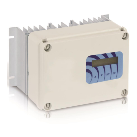
- Page 1 XV300K MASTER CONTROLLER FOR AC FANS...
-
Page 2: Table Of Contents
NDEX READ CAREFULLY................................. 3 PRELIMINARY INSPECTIONS - WARRANTY .......................... 3 DISPOSAL .............................. 3 XV300K – USE FEATURES ..............................3 Coding ....................................3 TECHNICAL CHARACTERISTICS ............................4 MECHANICAL INSTALLATION .............................. 5 ELECTRICAL INSTALLATION ..............................5 LED WARNING SIGNALS ........................7 PANORAMIC VIEW CARDS ........................7 WIRINGS .................................... -
Page 3: Read Carefully
1 READ CAREFULLY CAUTION! BEFORE INSTALLING THE XV300K MASTER CONTROLLER READ CAREFULLY THE MANUAL AND FOLLOWS ALL THE INSTRUCTIONS HEREIN. WITH POWERED CONTROLLER DO NOT TOUCH THE INNER ELECTRICAL PARTS IN ANY CASE. IN COMPLIANCE WITH THE EU RULES AND THE EMC DIRECTIVES, PLEASE REMIND THAT THE XV300K CONTROLLER IS DESIGNED TO BE INCORPORATED ON MACHINES OR INTEGRATED ON CONTROL PANELS AND THEREFORE IS TO BE CONSIDERED AS A COMPONENT. -
Page 4: Technical Characteristics
Power Current Current Power nominal max* dissipation (kVA) XV308K XV312K XV320K XV328K XV340K XV350K XV360K NOTE: The data are related to operate at 400V~ 50Hz. For 230V voltage supply or XV3xxK models at 440-460V all current are the same. (*) Max current refers to an enviroment temperature of 50°C for a maximum time of 10 second every 5 minutes. 5 TECHNICAL CHARACTERISTICS 230/400V~ +10%/-15%, (440/460V~ on demand) POWER SUPPLY... -
Page 5: Mechanical Installation
6 MECHANICAL INSTALLATION The XV300K regulator must be wall-mounted vertically, in order to guarantee adequate dispersion of heat in the area of air circulation and prevent obstructions to air flow in the dissipator zone. XV300K has IP55 grade protection, anyway protect it from corrosive liquids, gas, heat sources and position it preferably sheltered from the sun's rays. - Page 6 several engines provided the sum of the rated currents of the motors is less than 20% of the rated current of the control. We recommend not introduce any electromechanical device on the motor cable. If the control cable length exceeds 3 m, we suggest using shielded cable, connecting the shield only on the regulator. We suggest don’t connect the control 0 Volt to the Earth.
-
Page 7: Led Warning Signals
LED WARNING SIGNALS DL1: yellow, starts to flash with input signal at minimum and increases the flashing frequency as the signal rises. It goes on steady with signal = 100%. It follows the priority signal (see Basic Settings [BS] in the Factory Parameters menu). - Page 8 1592016130 XV300K EN MASTER r1.1 16.06.2015 XV300K 8/26...
-
Page 9: Wirings
8 WIRINGS Term. Description Application Serial RS485, Modbus RTU - master Serial connection line to a Slave controlled inverter/device T1 - Serial RS485, Modbus RTU - master Ground I/O Mass I/O Open immediately blocks the control. It External emergency input can be connected to the load temp. -
Page 10: Control Panel
9 CONTROL PANEL The control panel visualizes in real time the inputs and outputs of the adjuster and allows setting the parameters. It is provided with a back-illuminated LCD/OLED display and with four keys described below. (UP) Goes to the previous visualization / increases a (DOWN) Goes to the next visualization / decreases a parameter (ENT) Enters the menu and the parameters / confirms... -
Page 11: Language Setting
INPUT 1: Defines the percentage of the IN1 input among the following possible signals: 0..10V=, 4..20mA, pwm (100Hz type with variable average value). INPUT PWM: Defines the percentage of the control value detected in the input dedicated to the PWM input signal with variable frecuency (available INPUT only on demand). -
Page 12: Operating Parameters Menu - Chiller
LANG. Press again the key to save the setting. The asterisk at the right bottom indicates the language set. Press to return to the sate menu 11 OPERATING PARAMETERS MENU - CHILLER The operating parameters menu can be accessed from any visualization of the state menu, by pressing together the keys (hold the key pressed and press the key... -
Page 13: Heating Cycle Parameters [Hea] - Chiller
Maximum production pressure, above this the output is at the voltage P_MAX [IC] MotorMaxLim. Min. P2 25.0 Max. Full Scale Def. 25 bar Voltage/speed of the pressure point P1. [IC] Min. MotorMinLim Max. V2 Def. 20% Voltage/speed of the pressure point P2. [IC] Min. -
Page 14: Operating Parameters Menu - Dry Cooler
Maximum production pressure, below this the output is at the voltage P_MAX [IH] MotorMaxLim. Min. 0 bar Max. P1 Def. 5 bar Voltage/speed of the pressure point P2. [IH] Min. MotorMinLim Max. V2 Def. 20% Voltage/speed of the pressure point P1. [IH] Min. -
Page 15: Parameters Reading And Editing
12.1 PARAMETERS READING AND EDITING The parameters windows display the name of the parameter, the [identifying code] of the corresponding menu, the value of the parameter [IC] and the unit of measure. °C 12.0 to go to the parameter below; to go to the parameter above To change the value of the parameter press , the arrow and the value of... -
Page 16: Heating Cycle Parameters [Hea] - Dry Cooler
12.3 HEATING CYCLE PARAMETERS [HEA] – DRY COOLER Caution: The heating cycle can be replaced by a second cooling cycle [CO2] by changing the setting of the parameter Second Mode. Temperature of the voltage/V2 speed point. [IH] Min. T_MAX °C Max. -
Page 17: Operating Parameters Menu - Slave
13 OPERATING PARAMETERS MENU - SLAVE The operating parameters menus can be accessed from any visualization of the state menu, by pressing together the keys (hold the key pressed and press the key IMPO.SLAVE [IC] The menu windows include the menu name and the corresponding [identifying code]. -
Page 18: Working Parameters [Ic] - Slave
13.2 WORKING PARAMETERS [IC] – SLAVE Control signal of the Voltage V1/speed point. MIN. INPUT [IC] Min. 10 % Max. InMax Def. 10% Control signal of the Voltage V2/speed point. MAX INPUT [IC] Min. InMin Max. 100% Def. 95% Voltage/speed of signal command IN.MINIM. [IC] Min. -
Page 19: Factory Parameters Menu
COOL cycle: For V1 Limit > V1 of the active cycle, if the pressure/temperature is lower than P1/T1, the Voltage OUT (Vout%) will be fixed at the value of the V1 Limit (see for example the below chart 2). HEAT cycle: For V1 Limit > V1 of the active cycle, if the pressure/temperature is higher than P2/T2, the voltage OUT (Vout%) will be fixed at the value of the V1 Limit (see for example the below chart 4). -
Page 20: Basic Settings
15.1 BASIC SETTINGS PRESET. [IB] Allows to load one of the settings based on the below tables. Select one setting to speed the programming up. Caution: previous settings will be overwritten; as for the Master pre-settings the values of SPD1 and SPD2 will be of 20% and 90% respectively. - Page 21 (this parameter is displayed only if “IN.TYPE [IB]” is on pwm fv) Minimum input frecuency used for the PWM fv input. PWM min [IB] Min. 2 kHz Max. MaxPwm Def. 2kHz (this parameter is displayed only if “IN.TYPE [IB]” is on pwm fv) PWM max [IB] Maximum input frecuency used for the PWM fv input.
-
Page 22: Motor Settings
KICK START [BS] Enabling of the kick start. This parameter is set for loads that need a torque start to move at low speeds. ON (Def.): function enabled OFF: function disabled Factory settings reset: reset to standard parameters (except for the operating time of the adjuster). -
Page 23: Relay Settings
Higher voltage of the jump window. SUP.MAX.LIM.1 [IM] Min. Sup.Min.Lim.1 Max. Sup.Min.Lim.2 Def. 30% (this parameter is visualized only if “Suppress.1” is ON) The functions “Suppress.2” and “Suppress.3” with corresponding limits operate alike the “Suppress 1” and are prioritary functions on any operating cycle. 15.3 RELAY SETTINGS Enables the internal relay based on the following settings: Default (Def.) : enabled relay in a condition of regular operating, disabled... -
Page 24: Diagnosis
BAUDRATE [MB] Defines the transmission speed on channel RS-485 Possible modes: 9600bps, 19200bps (Def.), 38400bps 19200 bps PARITY [MB] Defines the type of parity on the serial transmission. Possibles modes: None (Def.), even, odd none BIT STOP [MB] Defines the parity bit in the serial transmission. Possible modes: 1=one bit (Def.), 2=two bits Adjuster’s maximum time to receive the setting value on Modbus transmission. -
Page 25: Real Time Clock
[IF REAL TIME CLOCK AVAILABLE] With clock option ON the display visualizes the date and time of the last stop next to the number of stops. 16 REAL TIME CLOCK The following functions are available only in the controllers provided with the related option and only with a backup battery type CR2032-3V (not provided) as represented in the image. - Page 26 1592016130 XV300K EN MASTER r1.1 16.06.2015 XV300K 26/26...