
Related Manuals for GE AvantaPure Professional Series


Summary of Contents for GE AvantaPure Professional Series
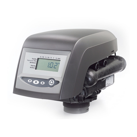
- Page 1 ® AvantaPure Professional Series Water Treatment System by GE Operations Manual Models: 268 Co-Current Conditioner 263 Three-Cycle Filter Writers Note: NEED NEW IMAGE...
-
Page 2: Table Of Contents
Table of Contents How To Use This Manual General Warnings And Safety Information System Operation Cycle Functions Equipment Installation Valve Layout Control Layout Location Selection Water Line Connection Drain Line Regenerant Line Connection Overflow Line Connection Electrical Connection Valve Camshaft Disinfection Of Water Conditioners AvantaPure Controller Display Icons... -
Page 3: How To Use This Manual
How To Use This Manual series controllers. This manual is a reference and will not include every system installation situation. The person installing this equipment should have: • Training in the AvantaPure series controllers and Autotrol brand valves • Knowledge of water conditioning and how to determine proper control settings Left Side Right Side... -
Page 4: General Warnings And Safety Information
General Warnings And Safety Information Electrical There are no user-serviceable parts in the AC adapter, motor, or controller. In the event of a failure, these should be replaced. • All electrical connections must be completed according to local codes. • Use only the power AC adapter that is supplied. - Page 5 General • Observe all warnings that appear in this manual. • Keep the media tank in the upright position. Do not turn upside down or drop. Turning the tank upside down will cause media to enter the valve. • Operating ambient temperature is between 34F (1C) and 120F (49C).
-
Page 6: System Operation Cycle Functions
System Operation Cycle Functions 1. Service (Downflow) 2. Backwash (Upflow) 3. Brine/Slow Rinse (Downflow) 4. Repressurized Cycle (Hard Water Bypass Flapper Open) 5. Fast Rinse (Downflow) 6. Brine Refill System Operation Cycle Functions... - Page 7 Cycle Water Flows From Regenerant Tank SERVICE BACKWASH BRINE/SLOW RINSE To Regenerant Tank BRINE REFILL REPRESSURIZE FAST RINSE Rev H...
-
Page 8: Equipment Installation
Equipment Installation Valve Layout One Piece Valve Disc Spring Valve Discs Control Module Mount Refill Controller Injector and cap Regenerant Tube Connection Optical Sensor Camshaft Motor Outlet Drain Inlet Injector Screen Backwash Filter Drain Control Equipment Installation... -
Page 9: Control Layout
AvantaPure Controller LCD Display x100 Down Button Manual Regen Button Set Button Up Button Chlorine Generator Outlet AC Adapter (low voltage) Input For Future Use Main Motor & Optical Sensor Connection Turbine Input or Dry Contact Signal Input Control Layout Rev H... - Page 10 Model Number Recharge Style Media Tank Size Resin Volume Recharge (Salt) Tank Size Salt Storage Drain Water Rate Service Connection Size Drain Connection Size Recharge (Brine) Connection Size Installation Space Requirements Shipping Weight Rev H...
-
Page 11: Location Selection
Location of a water treatment system is important. The following conditions are required: WRITERS NOTE: LEVELING FEET? • Level platform or floor • Room to access equipment for maintenance and adding regenerant (salt) to tank. • Ambient temperatures over 34F (1C) and below 120F (49C). •... - Page 12 return to normal. A protective cover should assist with high temperature applications. • Insects — The controller and valve have been designed to keep all but the smallest insects out of the critical areas. Any holes in the top plate can be covered with a metal foil ductwork tape.
- Page 13 Dimensions 17.6 (447) 16.8 (427.1) 19.8 (503.8) 20.5 (521.1) 35.1 (890.4) 5.0 (127) 2.5 (63.5) 55 (1398.1) 60.7 (1541.6) 53.4 (1356.6) 32.2 (817.5) 36.9 (938.1) 28.2 (715.9) Rev H...
- Page 14 Typical System Layout Bath Tub Lavatory Toilet Kitchen Outside Outside Faucet Faucet Hot Water Outlet Water Heater Laundry Tubs Pump Meter Floor Drain Figure 2 Softened Water Flow Diagram. Bath Tub Lavatory Toilet Kitchen Outside Outside Faucet Faucet Hot Water Grounding Soft Water Outlet...
- Page 15 The Pro Elite system is shipped with several parts unassembled. When parts are removed from the packing, they should be inspected for damage. If any parts are damaged or missing, contact your supplier. WARNING: When the carton is first opened, the softener will be standing upright. The salt tank will be turned over and covering the softener (Figure ).
- Page 16 To assemble the Media Tank: 1. If the floor under the media tank is uneven, the leveling feet may be installed. Slowly lay the tank on its side. Press or tap the feet into the pockets. WARNING: The media tank contains loose particles that will shift. If the tank is turned upside down or laid back quickly, the particles may enter the valve.
-
Page 17: Water Line Connection
A bypass valve system should be installed on all water conditioning systems. Bypass valves isolate the conditioner from the water system and allow unconditioned water to be used. Service or routine maintenance procedures may also require that the system is bypassed. The illustrations below show the two common bypass methods. - Page 18 Figure 7 Grounding Strap The inlet water must be connected to the inlet port of the valve. When replacing non-Autotrol valves, the inlet and outlet may be reversed. It is also possible for the plumbing to be installed in an opposite order.
- Page 19 Drain Line Connection. Regenerant Line Connection Overflow Line Connection AvantPure Controller, Programming Conventions Programming Levels I, II, and III Placing the Conditioner Into Operation Level I Programming Installation Instructions...
-
Page 20: Drain Line
Right Way Drain Line... -
Page 21: Regenerant Line Connection
Regenerant Line Connection (not used with 3-cycle filter system) Parts List *Teflon is a trademark of E.I. duPont de Nemours. Regenerant Line Connection... - Page 22 Regenerant Line Connection...
-
Page 23: Overflow Line Connection
Overflow Line Connection “overflow” to the drain instead of spilling on the floor. This fitting should be on the side of the cabinet or regenerant tank. Most tank manufacturers include a post for the tank overflow connector. To connect the overflow line, locate hole on side of tank. Insert overflow fitting into tank and tighten with plastic thumb nut and gasket as shown (Figure 11). -
Page 25: Electrical Connection
CAUTION: NOTE: Input AC Adapter Application Part Number Voltage Standard wall-mount 120V 60Hz Standard indoor 1000811 AC adapter application Outdoor rated AC 120V 60Hz UL listed for 1235448 adapter outdoor installations 120 VAC AC Adapters: NOTE: The power source should be constant. Be certain the AC adapter is not on a switched outlet. - Page 26 System Operation Treated Water (Downflow) Untreated water is conditioned as it flows through the resin bed and up the riser. If the model selected at first start-up was 268r, this is a system that will refill the salt tank at the start of a regeneration cycle. When a regeneration cycle begins, the salt tank is filled and brine is allowed to develop before Cycle 1 starts.
- Page 27 Cycle Water Flows From To Regenerant Regenerant Tank Tank Service Backwash Regenerant Draw/ Repressurize Fast Rinse Refill Slow Rinse...
-
Page 28: Valve Camshaft
Treated Water Indicator (normal operation) Treated Water Slot = Treated Water - normal operation mode = Backwash Cycle = Regenerant Draw Cycle (not used in filter mode) = Slow Rinse Cycle (not used in filter mode) = System Pause = Fast Rinse Cycle 1 = Backwash Cycle 2 (not used in filter mode) = Fast Rinse Cycle 2 (not used in filter mode) = Regenerant Refill (not used in filter mode) -
Page 29: Disinfection Of Water Conditioners
Figure 14 - Performa Valve 6 Rinse Drain 4 Outlet Valve 2 Bypass Valve 7 Backwash Drain Valves 3 Inlet Valve 5 Refill Valve 1 Regenerant Valve The materials of construction of the modern water conditioner will not support bacterial growth, nor will these materials contaminate a water supply. - Page 30 Calcium Hypochlorite Calcium hypochlorite, 70% available chlorine, is available in several forms including tablets and granules. These solid materials may be used directly without dissolving before use. 1. Dosage A. Two grains (approximately 0.1 ounce [3 mL]) per cubic foot. 2.
-
Page 31: Avantapure Controller
AvantaPure Controller Power Loss Memory Retention Motor Controller Memory NOTE: Water flow to the valve can be turned on or bypassed when the controller is powered up for the first time. Variable Reserve Function end-user’s water usage schedule. A variable reserve saves salt and water by only regenerating when absolutely necessary, and ensures enough soft water for typical high-water usage days. -
Page 32: Display Icons
Display Icons Figure 15 x100 In normal operation and during programming, only a few of the icons will actually be displayed. 1. Displays amount of conditioning capacity remaining. 2. "PM" indicates that the time displayed is between 12:00 noon and 12:00 midnight (there is no AM indicator). -
Page 33: Keypad - Buttons
Keypad — Buttons Programming Conventions UP for up arrow DOWN for down arrow SET for set REGEN for regeneration P/R for press and release HOLD for press and hold X sec for a number of seconds to press the button and hold it down Keypad —... -
Page 34: Things You Might Need To Know
Things You Might Need to Know Level II Programming Level II Programming Things You Might Need to Know... -
Page 35: Programming Overview
Programming Overview NOTE: NOTE: Level I Programming Time of Day Day of Week Time of Regeneration • Setting Time of Day NOTE: Programming Overview... - Page 36 • Setting Day of Week • Setting Regeneration Time...
-
Page 37: Level Ii Programming
268 Conditioner Operation Type 263 Filter Operation Type INJECTOR SELECTION* REGEN SA BACKWASH 1 CAPACITY GAL SLOW RINSE SELECT LANGUAGE FAST RINSE 1 CLOCK MODE BACKWASH 2 UNITS OF MEASURE FAST RINSE 2 BACKWASH OPERATION TYPE 268* FAST RINSE SERVICE INTERVAL OPERATION TYPE 263* CHLORINE GENERATOR SERVICE INTERVAL... - Page 38 NOTE: Regeneration on specific day is used to provide regeneration when water demands are not steady. Example: If the weekdays have low usage and the weekend is high, then regeneration every three days will not meet the requirements. The calendar override days between regeneration must be set to zero to enable regeneration on specific days.
- Page 39 Table 1 AvantaPure 268 Co-Current Valve Capacity/Salt Dosage Reference This table is for reference only. Your AvantaPure Water Treatment Professional selects the model numbers based on your specific application requirements. Tank Diameter Total Salt Total Capacity Injector Resin Cu. Ft. Dosage lbs Kilograins Type...
- Page 40 The default capacity setting is accurately calculated when the model number is entered by the factory. The capacity can be changed to operate "custom systems". Contact your AvantaPure Water Treatment Professional before adjusting the capacity setting. Default capacities are shown in Table 1. Filter capacity is set in gallons or cubic meters.
- Page 41 • Viewing the Injector Type • Adjusting the Cycle Times Conditioner Cycle Times 268 Conditioner Cycle Range Backwash 1-50 minutes Fast Rinse 1-30 minutes Refill time does not appear as this cycle time is determined by the salt setting. *The controller calculates the Slow Rinse default time on injector type, system size and salt dosage.
- Page 42 The controller has the capability to produce a low level of chlorine during the brine draw stage of regeneration. It can also sense if there is any brine present during the time when brine draw is occurring. This parameter can be adjusted to the following: 0 = Chlorine Generator with Salt Check disabled 1 = Salt Check only 2 = Chlorine Generator with Salt Check enabled...
-
Page 43: Level Iii Programming
Historical information can be retrieved from the controller be pressing the SET and DOWN buttons simultaneously, with the controller in the home position. Release both buttons when the controller displays MODEL NUMBER. Press the UP or DOWN buttons to navigate to each setting. The readout will scroll across the top of the display and the value will be displayed below the readout. -
Page 44: Placing Conditioner Into Operation
Placing Conditioner Into Operation Conditioner and Filter Start-Up NOTE: Function Display Text (268) Display Text (263) - Page 45 WARNING: tank into the valve or the plumbing. In the ¼ open position, you should hear air slowly escaping from the valve drain line. NOTE: 263 Filter - advance control back to the treated water position, proceed to Step 12. NOTE: We recommend that you do not put regenerant into the tank until after the control valve has been put into operation.
- Page 46 9. Engage the refill cycle to prime the line between the regenerant tank and the valve (conditioner only). A. Slowly open the main water supply valve again, to the fully open position. Be sure not to open too rapidly as that would push the media out of the media tank.
-
Page 47: Avantapure Exploded View
AvantaPure Exploded View Warning: Do not use the flow control ball with #10A. AvantaPure Exploded View... -
Page 48: Avantapure Parts List
Part Qty. Code Description Qty. 1244651 Valve Assembly w/o Flow Controls Plumbing Adapter Kits: 1235338* Top Plate, AvantaPure Series Valves 1001606 3/4-inch Copper Tube Adapter Kit 1235339 Valve Disc Spring, One Piece, Performa 1001670 1-inch Copper Tube Adapter Kit Valve 1001608 22-mm Copper Tube Adapter Kit 1242282 Cover, Valve,AvantaPure Controller 1001613 3/4-inch CPVC Tube Adapter Kit... -
Page 49: Troubleshooting
ERR 1 is displayed. Program settings have been corrupted. Press any key and reset model number. ERR 3 is displayed. Controller does not know the position of Wait for two minutes for the controller to the camshaft. Camshaft should be return to Home position. - Page 50 1. Brine tank a. Uncontrolled brine refill flow rate. a. Remove brine control to clean ball and seat. overflow. b. Air leak in brine line to air check. b. Check all connections in brine line for leaks. Refer to instructions. c.
- Page 51 8. System using a. Foreign matter in valve causing a. Remove brine control and flush out foreign more or less salt incorrect flow rates. matter. Advance control to brine/slow rinse, than regenerant to clean valve (after so doing position setting. control to "fast rinse”...
- Page 52 VIEWING AND SELECTING MODEL NUMBERS AvantaPure 268 Co-Current Conditioner AvantaPure 263 3-Cycle Filter Capacity/Salt Dosage (268 Co-Current Conditioner) Model Number (263 Filter Valve) Viewing the Model Number Note To Change The Model Number Set Time of Day Day of the Week To Change Time of Regeneration ERROR 3 Rev H...