
Related Manuals for GE Baker Hughes PanaFlow LC XMT1000


Summary of Contents for GE Baker Hughes PanaFlow LC XMT1000
- Page 1 Flow PanaFlow™ LC User’s Manual bhge.com 910-327 Rev. A Sep 2019...
- Page 3 Contact your BHGE representative for the most current information. The Baker Hughes logo is a trade mark of Baker Hughes, a GE company. The GE Monogram is a trademark of the General Electric...
- Page 4 [no content intended for this page]...
- Page 5 Contents Chapter 1. Introduction 1.1 System Description................1 1.2 Theory of Operation .
- Page 6 Contents 3.3.1c Selecting a Channel Measurement to Display ......... .36 3.3.1d Totalizer Display.
- Page 7 Contents Chapter 4. Error Codes and Troubleshooting 4.1 Introduction ................. . 73 4.2 Error Classification and Error Codes .
- Page 8 Contents D.1 Input Registers Map ................125 Appendix E.
- Page 9 Contents H.7 Configurable Measurements..............155 H.8 Channel Transducer Block .
- Page 10 Contents viii PanaFlow™ LC User’s Manual...
- Page 11 Preface Product Registration Thank you for purchasing a model PanaFlow™ LC from BHGE. Please register your product at https://info.industrial.ai/New-Product-Registration-LP.html for product support such as the latest software/firmware upgrades, product information and special promotions. Services BHGE provides customers with an experienced staff of customer support personnel ready to respond to technical inquiries, as well as other remote and on-site support needs.
- Page 12 Preface Auxiliary Equipment Local Safety Standards The user must make sure that he operates all auxiliary equipment in accordance with local codes, standards, regulations, or laws applicable to safety. Working Area WARNING! Auxiliary equipment may have both manual and automatic modes of operation. As equipment can move suddenly and without warning, do not enter the work cell of this equipment during automatic operation, and do not enter the work envelope of this equipment during manual operation.
- Page 13 Preface Environmental Compliance RoHS The PanaFlow™ LC fully complies with RoHS regulations (Directive 2011/65/EU). Waste Electrical and Electronic Equipment (WEEE) Directive BHGE is an active participant in Europe’s Waste Electrical and Electronic Equipment (WEEE) take-back initiative (Directive 2012/19/EU). This equipment has required the extraction and use of natural resources for its production. It may contain hazardous substances that could impact health and the environment.
- Page 14 Preface [no content intended for this page] PanaFlow™ LC User’s Manual...
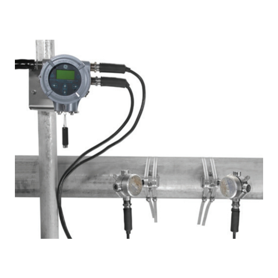
- Page 15 Chapter 1. Introduction Chapter 1. Introduction Thank you for purchasing a model PanaFlow™ LC from BHGE. Please register your product at https://info.industrial.ai/New-Product-Registration-LP.html for product support such as the latest software/firmware upgrades, product information and special promotions. 1.1 System Description The PanaFlow™ LC flowmeter is a one, two, or three channel ultrasonic transit time flowmeter that utilizes clamp-on transducers on external pipe surfaces to allow for uninterrupted flow operation during flow measurement.
- Page 16 Chapter 1. Introduction 1.2 Theory of Operation The PanaFlow™ LC uses a procedure called Transit-Time Flow Measurement. In this method, the flowmeter transmits ultrasonic pulses through a moving liquid. The pulses that travel in the same direction as the fluid flow (downstream) travel slightly faster than the pulses that travel against the fluid flow (upstream).
- Page 17 Chapter 2. Installation Chapter 2. Installation 2.1 Installation Guidelines This section provides general information with respect to the mechanical and electrical installation, and should be thoroughly reviewed before the system is installed. To ensure safe and reliable operation of the PanaFlow™...
- Page 18 Chapter 2. Installation 2.2 Unpacking the PanaFlow LC System Before removing the PanaFlow™ LC from its box, please inspect both the box and the instrument carefully. Each instrument manufactured by BHGE is warranted to be free from defects in material and workmanship. Before discarding any of the packing materials, account for all components and documentation listed on the packing slip.
- Page 19 Chapter 2. Installation Unpacking the PanaFlow LC System (cont.) Model & Serial Number (Boston) Model & Serial Number (Shannon) Certification (US/CAN, IECEx/ATEX) Certification (US/CAN, IECEx/ATEX) [FISCO] [Standard] Figure 4: Typical XMT1000 Labels PanaFlow™ LC User’s Manual...
- Page 20 Chapter 2. Installation 2.3 Site Considerations Proper installation of the PanaFlow™ LC is important to achieve optimum performance from the system. The following installation recommendations provide general guidelines of how this system should be installed. If the following recommendations cannot be met, please consult the factory for a more detailed review of the application to see what performance may be achievable.
- Page 21 Chapter 2. Installation 2.4.1 Strap Clamping Fixture The Strap Clamping Fixture (SCF) (see Figure 5 below) acts as a spacing device, a transducer holder, and a transducer aligner. The SCF includes two U-shaped blocks connected by a slotted bar and four hose straps. The SCF is strapped around the pipe, and the blocks are used to hold the transducers in position for accurate measurements.
- Page 22 Chapter 2. Installation 2.5 Determining the Number of Traverses The first step in the installation is determining the number of traverses (see Figure 6 below). The transducers can be mounted using one of two methods: • Even number of-traverse method - the transducers are mounted on the same side of the pipe and the ultrasonic signal is transmitted from one transducer to the other by reflection off the opposite pipe wall.
- Page 23 Chapter 2. Installation 2.6 Precautions Prior to installation the clamping fixture, it is HIGHLY recommended to keep the following in mind: 1. Position the clamp-on fixture(s) and transducer system so that there are at least 10 pipe diameters of straight, undisturbed flow upstream and 5 pipe diameters of straight, undisturbed flow downstream from the measurement point (see Figure 7 below).
- Page 24 Chapter 2. Installation 2.6.1 Even Number of Traverse Method Note: The instructions in this section can also be used for a multiple-traverse method. However, you must use an EVEN number of traverses. The distance the signal travels from one side of the pipe wall to the opposite side of the pipe wall is considered one traverse.
- Page 25 Chapter 2. Installation Figure 9 below shows a completed even-traverse installation without the transducers. Proceed to the section on mounting the transducers later in this chapter. Figure 9: Finished SCF Installation without Transducers 2.6.2 Odd Number of Traverse Method Note: The instructions in this section can also be used for a multiple-traverse method. However, you must use an ODD number of traverses.
- Page 26 Chapter 2. Installation 2. Prepare the pipe where you intend to place the SCF by making sure it is clean and free of loose material. Sanding, though usually not required, may be necessary to remove any high spots. However, be careful to preserve the original curvature of the pipe. 3.
- Page 27 Chapter 2. Installation 6. From the other mark on the top of the pipe, measure around the pipe in the opposite direction a distance equal to 1/4 of the pipe circumference, or the same distance used in Step 5. Use the center punch to make a mark at this point.
- Page 28 Chapter 2. Installation Figure 15: SCF Odd Number of Traverse Installation, Step 8 Figure 16 below shows an odd traverse installation without the transducers. Proceed to the section on mounting the transducers later in this chapter. Figure 16: Odd Number of Traverse SCF Installation without Transducer PanaFlow™...
- Page 29 Chapter 2. Installation 2.7 Transducer Installation For any of the fixtures above except for the SPCF, the last step in the installation is mounting the transducers into the clamping fixture. Although not all transducer models are installed the same way, the following information provides some general guidelines to help you.
- Page 30 Chapter 2. Installation Figure 19: Transducer Mounting, Step 1 2. Apply a thin bead of couplant to one of the transducers. A bead approximately the size of a toothpaste bead should be placed down the center of the transducer face. Figure 20: Transducer Mounting, Step 2 BHGE supplies an ultrasonic couplant for your clamp-on installation.
- Page 31 Chapter 2. Installation 3. Determine the upstream and downstream ends of the pipe and place the appropriate transducer into the corresponding block on one of the sub-assemblies. Make sure the transducer cable connector faces away from the center of the installation. Figure 21: Transducer Mounting on UCF (Top Left), MCF (Top Right), GCF (Bottom Left), and SCF (Bottom Right) 4.
- Page 32 Chapter 2. Installation Figure 22: SCF Clamping Fixture (Top Left), UCF Clamping Fixture (Top Right), GCF Clamping Fixture (Bottom Left), MCF Clamping Fixture (Bottom Right) 2.8 Installing the V Series Clamping Fixture and Transducers To install the V Series clamping fixture and transducers, complete the following steps: PanaFlow™...
- Page 33 Chapter 2. Installation 2.8.1 Installing the Fixture 1. Position the half of the clamping fixture with the threaded rods around the pipe, as shown in Figure 23 below. Orient the fixture in the 3 o’clock position on a horizontal pipe. 2.
- Page 34 Chapter 2. Installation Figure 25: Installing Nuts onto the Fixture 2.8.2 Installing the Transducers 1. Apply a bead of coupling 6 mm (0.25 in.) wide along the entire length of each transducer face, as shown in Figure 26 below. Figure 26: Couplant on Transducer Face Note: Do not slide the transducer with couplant along the surface of the pipe when mounting the transducer.
- Page 35 The PI clamping fixture holds transducers on pipes from 12 to 24 in. in diameter. It comes with either a chain or strap, depending on the selection made with the initial order from GE. To install the fixture and transducers, complete the following steps: 2.9.1 Surveying the Pipe...
- Page 36 Chapter 2. Installation Figure 29: Marking Circumferential Lines on the Pipe 3. Line up the zero scale of the layout tape at the desired location of the first transducer. (For a typical installation, this point will be the 3 o’clock position on a horizontal pipe.) Mark each of the two circumferential lines at the zero point.
- Page 37 Chapter 2. Installation 180° & C/2 180° & C/2 Figure 32: Measuring the 180° Point from Top and Bottom 2.9.2 Installing the First Bracket with a Chain The following steps describe how to install the PI fixture with a supplied chain or strap. 1.
- Page 38 Chapter 2. Installation Figure 34: Positioning the CFG-PI Holder Bracket 5. Loosen the transducer hold-down screw and tighten the J-hooks on the clamping fixture. Be sure the bracket has not moved from its position. 2.9.3 Installing the Second Bracket with a Chain 1.
- Page 39 Chapter 2. Installation Mark on Opposite Scribe Line Rear Edge of Second Block Figure 36: Line Up Rear Edge of Bracket with 180° Scribe Line The spacing should now appear similar to that in Figure 37 below. Figure 37: CFG-PI Fixture with Calculated Spacing 2.9.4 Installing the Transducers 1.
- Page 40 Chapter 2. Installation Figure 38: Couplant on Transducer Face Note: Do not slide the transducer with couplant along the surface of the pipe when mounting the transducer. 3. With one hand, mount one transducer into the PI fixture. With the other hand, tighten the thumbscrew, gradually pushing the transducer down to the pipe surface.
- Page 41 Chapter 2. Installation Figure 39: LEFT: Stainless Steel Junction Box, RIGHT: Aluminum Junction Box 2.11.1 Installing the Junction Box Mount the aluminum (5lbs) or stainless steel (15lbs) junction box using the included mounting plate to a wall (hardware supplied by end user) or a 2 inch pipe (hardware supplied with J-box). See Figure 40 for reference. Figure 40: Aluminum J-box mount to 2"...
- Page 42 Chapter 2. Installation 2.11.2.1 Transducer Wiring (ATEX installations) 1. Thread one end of armored cable into the meter head and the other into the junction box on the back of the transducer (see Figure 1 on page 1 for reference). 2.
- Page 43 Chapter 2. Installation Figure 42: PanaFlow LC Single Channel Set 2.11.3 Two Channel Set Up Components of a two channel PanaFlow LC will be a meter head, 4 transducer cables and two sets of transducers, 2 channel junction box and clamping fixtures. Mount meter head to a two inch post using included hardware or another location following local electrical and building codes.
- Page 44 Chapter 2. Installation 8. Secure Black wire of channel two downstream RG62 cable to the CH2 (blue box in Figure 41) RTN terminal directly below the DN terminal of the XMT1000 backplane. 9. Secure red wire of channel two upstream RG62 cable to the CH2 (blue box in Figure 41) UP terminal of the XMT1000 backplane.
- Page 45 Chapter 2. Installation XMT1000 Meter Head Trunk Cable 3 Channel Junction Box Figure 44: XMT1000 Trunk cable Placement 2. Thread one end of transducer cables into 3 channel junction box as shown in Figure 45. (Cable locations in Figure 45 are for reference only. Transducer cables can be placed in any orientation) Figure 45: XMT1000, 3 Channel Junction Box PanaFlow™...
- Page 46 Chapter 2. Installation 3. Thread CH1 UP transducer cable into upstream junction box of the transducer set you will use for channel one. Repeat for CH1 DN and remaining channels. 4. Remove cover on transducer junction box and terminate BNC end of transducer cable to the BNC on the transducer for each channel.
- Page 47 Chapter 3. Programming Chapter 3. Programming 3.1 Introduction This chapter has instructions for programming various features of the PanaFlow™ XMT1000 flow transmitter. In this chapter, we will list all available options. The user can then change the User Preferences and Inputs/Outputs settings, Programming for flow measurements and Calibration to meet their needs. IMPORTANT: Not all users will have access to all of the menus.
- Page 48 Chapter 3. Programming Key Symbol Key Name Functions Up Arrow Key To navigate among menu choices, pages or increase/decrease numeric entries Down Arrow Key To navigate among menu choices, pages or increase/decrease numeric entries 3.1.2 Indicator Lights • The blue light on the top right above the display is the Power Indicator that is normally lit when the instrument is powered.
- Page 49 Chapter 3. Programming • Finally, the Measurement View (Refer Figure 48) This screen (Refer Figure 48) will be referred to as “Measurement View” throughout this chapter. User can choose the measurement to be displayed in this view from a list of options. The Error indicator at the bottom left of the display will be blank if the meter has no error.
- Page 50 Chapter 3. Programming 2. In the Display Measurement select [Composite], then press [ENTER]. 3. Then, select the measurement you would like to see on the Measurement View and press [ENTER]. Velocity Display Measurement Composite Velocity Composite 0.000 Channel 1 Volumetric (Act) Channel 2 Volumetric (Std) Channel 3...
- Page 51 Chapter 3. Programming Display Measurement Channel 1 Ch 1 Velocity Composite Velocity 0.000 Channel 1 Volumetric (Act) Channel 2 Volumetric (Std) Channel 3 Mass Flow (or) Channel 1 Ch1/Inv Vol Measure Velocity Fwd Vol Inventory Raw Velocity 0.000 Avg Vol Flow Rate Rev Vol Inventory Ch 1 Velocity Batch Vol Total...
- Page 52 Chapter 3. Programming 2. In the Display/Totalizer, select [Composite] or [Channel x], then press [ENTER]. 3. Then, select the totalizer measurement you would like to see on the Measurement View and press [ENTER]. 4. Press [] button on the keypad until the [or ] is highlighted to stop or start the totalizing respectively.
- Page 53 Chapter 3. Programming 3.3.2 Log-in and Primary Pages To Log-in into the meter perform the following steps: 1. Press [] until the lock icon on the meter’s Measurement View display is highlighted, then press [ENTER]. 2. In the Main Menu Scroll down and select [Program], then press [ENTER]. 3.
- Page 54 Chapter 3. Programming IMPORTANT: If the keypad has not been pressed for 5 minutes, the XMT1000 exits the Program and returns to displaying measurements. Because changes can only be retained after the user confirms them, the meter discards any unconfirmed configuration changes. 3.4 System Settings 3.4.1 Selecting Units The operator can select the preferred units of measurements.
- Page 55 Chapter 3. Programming Table 2: Unit groups and supported units Unit Group Supported Metric Units Supported English Units Mass Units kg/s, kg/min, kg/h, kg/d, Ton/s, lb/s, lb/min, lb/h, lb/d, klb/s, klb/min, Ton/min, Ton/h, Ton/d klb/h, klb/d, STon/s, STon/min, STon/h, STon/d Volumetric Totals Units m³, L, Sm³, SL, ML, Mm³...
- Page 56 Chapter 3. Programming 3.5 Inputs and Outputs 3.5.1 Modbus Port Settings The XMT 1000 meter supports digital communications using the MODBUS/RTU protocol, with 3-wire RS-485 as the physical layer interfaces. Baud rate can be specified from 2400 to 115,200 bits per second (bps), with selectable parity, and number of stop bits (Default = 115200, Even, 1 Stop Bit).
- Page 57 Chapter 3. Programming 3.5.2 Standard Analog Output The XMT1000 has one Analog Output and one Digital Output in Standard configuration. 3.5.2a Setting up Analog Output The XMT1000 meter has one Analog Output in standard configuration. For additional Analog outputs Optional I/O boards may be purchased. Use steps as in section “Log-in and Primary Pages” to navigate to the Input/Output settings page.
- Page 58 Chapter 3. Programming Table 5: Analog Output Error Handling with Path Error Handling set to ON Expected Composite Error displayed in Volumetric(Act) Analog Output Ch1 in Error Ch2 in Error Ch3 in Error Meter behavior Response No Error Measured mA proportional to the Composite Measured Composite Volumetric(Act)
- Page 59 Chapter 3. Programming Measurement Type/Comp Measurement Type Input/Output Analog Output (Std) 4-20mA Velocity Analog Output (Std) Measurement Type Composite Volumetric (Act) Digital Output (Std) 4-20mA Base Value Channel 1 Volumetric (Std) Option Comm (Slot 1) Full Value Channel 2 Channel 3 Mass Flow Option I/O (Slot 2) Calibrate...
- Page 60 Chapter 3. Programming 4. Select [Calibrate 4mA] and check if the reading on the multimeter reads 4.00mA ± 0.01mA. If the value on the multimeter is not 4.00mA ± 0.01mA, input the value read on the multimeter into the Calibrate 4mA value and press [ENTER]. Check multimeter again verify the Current reads 4.00mA within ±0.01mA.
- Page 61 Chapter 3. Programming 3.5.3 Standard Digital Output 3.5.3a Setting up Pulse Output To program a Pulse Output, use steps as in section “Log-in and Primary Pages” to navigate to the Input/Output settings page: 1. In Meter Menu highlight [Digital Output (Std)] and press [ENTER]. Then select [Pulse] option. 2.
- Page 62 Chapter 3. Programming Pulse Input/Output Digital Output (Std) Polarity Polarity Analog Output (Std) Negative Pulse Measurement Digital Output (Std) Positive Pulse Value Frequency Option Comm (Slot 1) Pulse Width Alarm Option I/O (Slot 2) Pulse Measurement Type/Comp Measurement Type Polarity Composite Fwd Vol Batch Measurement Type...
- Page 63 Chapter 3. Programming 3.5.3b Setting up Frequency Output To program a Frequency Output, use steps as in section “Log-in and Primary Pages” to navigate to the Input/Output settings page: 1. In Meter Menu highlight [Digital Output (Std)] and press [ENTER]. Then highlight [Frequency] option and press [ENTER].
- Page 64 Chapter 3. Programming Frequency Measurement Type/Comp Input/Output Digital Output (Std) Measurement Type Measurement Type Velocity Analog Output (Std) Composite Volumetric (Act) Pulse Channel 1 Base Value Digital Output (Std) Volumetric (Std) Frequency Channel 2 Full Value Option Comm (Slot 1) Mass Flow Channel 3 Full Frequency...
- Page 65 Chapter 3. Programming Table 11: Frequency Output Error Handling with Path Error Handling set to ON Expected Composite Error displayed in Volumetric(Act) Analog Output Ch1 in Error Ch2 in Error Ch3 in Error Meter behavior Response No Error Measured Frequency Composite proportional to the Volumetric(Act)
- Page 66 Chapter 3. Programming 3.5.3d Setting up Alarm Output To program an Alarm Output, use steps as in section “Log-in and Primary Pages” to navigate to the Input/Output settings page: 1. In Meter Menu highlight [Digital Output (Std)] and press [ENTER]. Then select [Alarm] option. 2.
- Page 67 Chapter 3. Programming Alarm State Alarm State Digital Output (Std) Alarm Input/Output Alarm State Normally Closed Analog Output (Std) Normally Closed Alarm Type Pulse Normally Open Normally Open Digital Output (Std) Measurement Type Frequency Option Comm (Slot 1) Fail Safe Fail Safe Alarm Value Alarm...
- Page 68 Chapter 3. Programming 3.5.4 Option Comm Slot-1 (optional) 3.5.4a Option Slot-1 Configured as HART Use steps as in section “Log-in and Primary Pages” to navigate to the Input/Output settings page. 1. Then highlight [Option Comm (Slot 1)] and press [ENTER]. Then highlight [HART] and press [ENTER]. 2.
- Page 69 Chapter 3. Programming 3.5.5 Option I/O Slot-2 (Optional) For extended I/O capability XMT1000 supports an Optional I/O that provides 2 additional Analog Outputs (AO-AO), with up to 2 Analog Inputs (AI-AI) or 2 RTD (R-R) inputs. See Table 14 for all available options. Table 14: Optional I/O available options Input / Output Options Board Option #...
- Page 70 Chapter 3. Programming Analog Output (S2:1) Input/Output Analog Output (S2:1) Measurement Type Measurement Type/Comp Option I/O (Slot 2) AO-AOAI-R-1000-3W Velocity Analog Output (Std) Measurement Type Composite AO-AOAI-R-1000-3W Analog Output (S2:1) Volumetric (Act) Digital Output (Std) 4-20mA Channel 1 Analog Output (S2:2) Base Value Volumetric (Std) Option Comm (Slot 1)
- Page 71 Chapter 3. Programming 7. Select [Calibrate 4mA] and check if the reading on the multimeter reads 4.00mA ± 0.01mA. If the value on the multimeter is not 4.00mA ± 0.01mA, input the value read on the multimeter into the Calibrate 4mA value and press [ENTER]. Check the multimeter again verify that the Current reads 4.00mA within ±0.01mA.
- Page 72 Chapter 3. Programming Table 15: Analog Input Measurement Types Measurement Options for Analog Input Temperature, Pressure Input/Output Analog Input (S2:3) Option I/O (Slot 2) AO-AOAI-R-1000-3W Analog Input (S2:3) Measurement Type Analog Output (Std) Measurement Type Analog Output (S2:1) Temperature AO-AOAI-R-1000-3W Pressure Digital Output (Std) Analog Output (S2:2)
- Page 73 Chapter 3. Programming Figure 66: Option I/O Analog Input connections 3.5.5e Option IO (Slot2): Calibrating RTD Input 1. Insert RTD sensor and master RTD in temperature bath and turn ON, and set it to desired temperature set point. 2. Use steps as in section “Log-in and Primary Pages” to navigate to the Input/Output settings page. Refer to Figure 65 above, highlight [Option I/O (Slot 2)] and press [ENTER].
- Page 74 Chapter 3. Programming 3.6 Programming Menu Options The options in the Programming Page should be selected to best suit your application. The configurations selected in programming page are critical for accurate flow measurements. Incorrect programming settings can give erroneous measurements and impact accuracy. Note: Consult the factory or BHGE Services if you are unsure of the appropriate settings for your application.
- Page 75 Chapter 3. Programming Prigram/Composite Programming Pipe Pipe Size Pipe OD Pipe OD Composite Pipe Pipe Size Pipe OD UNIT: In Pipe OD Fluid 3.50 Channel 1 Pipe Material Pipe Wall Thickness 3.50 SAVE Path UNDO Channel 2 Lining Material Pipe ID Channel 3 Limits ALTER...
- Page 76 Chapter 3. Programming Table 17: Lining Materials Lining Material Other Tar Epoxy Glass Pyrex Asbestos Cement Mortar Rubber Teflon 3.6.2 Programming the Fluid The Fluid menu (see Figure 69) allows the user to specify all the parameters of the fluid flowing through the pipe that is required to ensure accurate ultrasonic flow rate measurements.
- Page 77 Chapter 3. Programming Table 18: Standard Fluid List Tracking On Tracking Off Ethanol Freon R12 Diesel Gasoline Liquid Nitrogen (-199C) Prigram/Composite Programming Density Fluid Density (Act) Density (Act) Composite Pipe Density Density (Act) UNIT: Lb/Ft^3 Density (Act) Channel 1 Fluid 62.4 Kinematic Viscosity Density (Ref)
- Page 78 Chapter 3. Programming Prigram/Composite Programming Path Path Configuration/Std Pipe Composite Path Configuration 1 Tilted Diameter (TD) Fluid Channel 1 2 Path (TD - TD) Path Weights Channel 2 Path Path Error Handling 3 Path (TD - TD - TD) Channel 3 Limits CH #1/Path Weight CH #1/Path Weight...
- Page 79 Chapter 3. Programming 3.6.5 Programming Advanced Settings Use steps as in section “Log-in and Primary Pages” to navigate to the Programming page. Refer to Figure 72 for the Path configuration options. 1. Highlight [Composite] and press [ENTER]. Scroll down and select [Advanced] and press [ENTER]. 2.
- Page 80 Chapter 3. Programming Table 19: Standard Transducers Transducer Number Transducer Model Number (#15/115) C-PT-05-H (#16/116) C-PT-10-H (#17/117) C-PT-20-H C-LP-40-HM C-LP-40-NM C-RW-312 C-RW-318 C-RS-401 C-RS-402 C-RS-403 UTXDR-407 UTXDR-408 C-RR-505 C-RR-510 C-RR-520 C-RR-591 C-RR-592 C-RR-H-595 C-RR-H-596 C-RR-H-597 C-AT-601 C-AT-602 C-AT-603 3.6.6b Programming the Placement The Placement menu allows the user to configure the mounting method of the transducers, based on the Transducer and Pipe programming done as specified in sections “Programming Menu Options”...
- Page 81 Chapter 3. Programming fixture on the pipe (see Figure 74). When exiting from the [Channel x] menu, the meter will display a message indicating that the Physical spacing of the transducers need to be adjusted to the value calculated by the XMT1000. 4.
- Page 82 Chapter 3. Programming Figure 74: Spacing Prigram/Channel 1 Programming Transducer Number Install Type/Clamp-on Composite Transducer #15 (C-PT-05-H) Standard Channel 1 Placement #16 (C-PT-10-H) Special Channel 2 Advanced #17 (C-PT-20-H) Channel 3 #23 (C-LP-40-HM) Transducer Frequency Clamp-on/Special Install Type/Clamp-on 200 KHz Transducer Frequency Standard 250 KHz...
- Page 83 Chapter 3. Programming 3.6.6c Programming Advanced Channel Settings 1. Refer to Clamp-on Calibration procedure for calibrating zero flow [Delta-T Offset]. 2. Refer to Section 3.6.7a Fluid Speed of Sound Calibration for Calibrating sound speed. 3. Scroll and highlight [Peak Detection] and press [ENTER]. Select [Automatic] for the meter to automatically pick the [Peak %].
- Page 84 Chapter 3. Programming Figure 77: Vitality screen - Warning 5. Click on [Cal-Trim-Test] [SOS calibration] . Expand the parameter. Figure 78: SOS calibrations Depending on the path configuration, the SOS values for SOS Measured (composite), SOS Ch1, SOS Ch2, SOS Ch3 will be displayed and dynamically updated.
- Page 85 Chapter 3. Programming 6. Enter the expected SOS value for your specific flow conditions in to fine-tune the meter [SOS Actual] for all its channels. 7. Click on , the displayed SOS values shall be updated accordingly. [Save CAL TO METER] 8.
- Page 86 Chapter 3. Programming Calibration Measurement Type/Comp Calibration Mode Measurement Type Cal Mode/Frequency Velocity Meter Factor Full Value Composite Calibration Mode Volumetric (Act) Base Frequency Channel 1 Gate Calibration Type Full Frequency Channel 2 Volumetric (Std) Frequency Reset K-Table Mass Flow Channel 3 Test Frequency Calibration Mode...
- Page 87 Chapter 4. Error Codes and Troubleshooting Chapter 4. Error Codes and Troubleshooting 4.1 Introduction The XMT1000 flow transmitter is a reliable, easy to maintain instrument. When properly installed and operated, as described in Chapter: Installation, the meter provides accurate flow rate measurements with minimal user intervention.
- Page 88 Chapter 4. Error Codes and Troubleshooting All the possible XMT1000 error code messages are discussed in this chapter, along with the possible causes and the recommended actions. When an error code is generated, it will appear in the lower left corner of the LCD screen, as discussed in Programming Chapter.
- Page 89 Chapter 4. Error Codes and Troubleshooting After you have tried eliminating/correcting for any most likely causes mentioned above, if error still exists, also check: 1. Incorrect programming on Error Limits or flow condition changes that now make previous programming invalid. 2.
- Page 90 Chapter 4. Error Codes and Troubleshooting Table 21: Flow Error description and Recommended Actions Error Code Problem Cause Recommended Action E1: SNR The Signal to Noise The acoustic signal from Check if the Active Tw ratio is low the process is very weak. measurement on upstream and This could be due to downstream transducers is valid.
- Page 91 Chapter 4. Error Codes and Troubleshooting Table 21: Flow Error description and Recommended Actions Error Code Problem Cause Recommended Action E5: Amplitude The signal amplitude This error may occur due Make sure the amplitude is within exceeds the to high signal attenuation the programmed limits.
- Page 92 Chapter 4. Error Codes and Troubleshooting Table 21: Flow Error description and Recommended Actions Error Code Problem Cause Recommended Action E23: Multi Two or more Two or more Check individual channel errors, Channel measurement measurement channels refer to this table for Accuracy channels are in error are in error;...
- Page 93 Chapter 4. Error Codes and Troubleshooting 4.4 Fluid and Pipe Problems If preliminary troubleshooting with the Error Code Messages and the Diagnostic Parameters indicates a possible problem, proceed with this section. Measurement problems fall into two categories: • Fluid problems •...
- Page 94 Chapter 4. Error Codes and Troubleshooting 4.4.2 Pipe Problems Pipe-related problems may result from improper choice in meter location or errors in programming. The following may result in problematic installations: • The collection of material at the transducer location(s). Accumulated debris at the transducer locations will interfere with the transmission of the ultrasound signals.
- Page 95 Chapter 4. Error Codes and Troubleshooting 4.6 Service Test Points Service tests points can be found on the XMT1000 Main board just inside the front cover. There are 6 pins found on the bottom left front side of the main PCB that are accessible to service personnel. These test points are easily connected by standard oscilloscope probes and allow the service person to look at critical signals.
- Page 96 Chapter 4. Error Codes and Troubleshooting Table 23: Gate connections TWIND: Transmit Window use DRTN with TWIND RWIND: Receive Window use DRTN with RWIND RCV: Receive signal allows the user to look at the receive signal before it is processed by the meter. It is usually looked at along with the TWIND and RWIND.
- Page 97 Chapter 4. Error Codes and Troubleshooting Table 24: System Error Description and Recommended Actions Error Code Error Message Description / Recommended Action Error: One or more flow measurement channels S6: Flow Measurement One or more flow measurement channels are in are in error;...
- Page 98 Chapter 4. Error Codes and Troubleshooting Table 24: System Error Description and Recommended Actions Error Code Error Message Description / Recommended Action Error: Initialization failed. Please verify all the S23: Initialization Initialization failed Failed configuration parameters. If error persists, contact BHGE factory Fault: DSP hardware failure detected.
- Page 99 Chapter 4. Error Codes and Troubleshooting 4.9 Transmitter Errors These errors are from the Transmitter subsystem. Should you encounter one of the Transmitter Errors, follow recommended actions as indicated in Table 26 and contact BHGE factory. Table 26: Transmitter Error Description and Recommended Actions Error Code Error Message Description / Recommended Action...
- Page 100 Chapter 4. Error Codes and Troubleshooting Error Code Error Message Description A6:(S2:3)Ch Not Error occurs when Analog Calibrate the Analog Input/RTD input. If error Calibrated Input/RTD(S2:3) are not persists after calibration, contact BHGE factory calibrated A7:(S2:4)Ch Not Error occurs when Analog Calibrate the Analog Input/RTD input.
- Page 101 Chapter 4. Error Codes and Troubleshooting 4.11 Diagnostics Data To determine the health of the meter, PanaFlow™ LC has built-in diagnostic parameters. Please refer to Table 28 below for diagnosing any problems with the system. If the meter shows errors and the diagnostics data indicate issues, fill in the User/Service record appendix before contacting BHGE factory.
- Page 102 Chapter 4. Error Codes and Troubleshooting Parameter Description Good Gain Up / Gain Gain setting >0 dB and <35 dB >35 dB or <0 dB Down • • In water applications, Gain spreads of 10dB or more under ideal between the channels can be conditions, gain an indication of a problem with should be greater than...
- Page 103 Chapter 4. Error Codes and Troubleshooting Parameter Description Good Signal Quality Up Signal quality of the >1000 <1000 upstream transducer Signal Quality Signal quality of the >1000 <1000 Down downstream transducer Amplitude Up Signal amplitude of >14 and <32 >32 or <14 the upstream transducer Amplitude Down Signal amplitude of...
- Page 104 Chapter 4. Error Codes and Troubleshooting [no content intended for this page] PanaFlow™ LC User’s Manual...
- Page 105 Chapter 5. Maintenance and Service Chapter 5. Maintenance and Service 5.1 Transducer Maintenance and Inspection WARNING! All equipment should be de-energized prior to servicing! PanaFlow™ LC shows low signal strength upon couplant dry out or extrude. Refer Couplant in “Transducer Installation” on page 15, Step 2 and “Transducer Installation” on page 15 for servicing couplant for proper operation of PanaFlow LC.
- Page 106 Chapter 5. Maintenance and Service [no content intended for this page] PanaFlow™ LC User’s Manual...
- Page 107 Appendix A. Specifications and Model Configurations Appendix A. Specifications and Model Configurations A.1 Operation and Performance Fluid Types Liquids: acoustically conductive fluids, including most clean liquids, and many liquids with small amounts of entrained solids or gas bubbles. Maximum void fraction depends on transducer, interrogation carrier frequency, path length, and pipe configuration.
- Page 108 Appendix A. Specifications and Model Configurations • CRR 0.5, 1.0, and 2.0 MHz • CAT 0.5, 1.0, and 2.0 MHz Process Fluid Temperature Range Local mount: -40°F to 185°F (-40°C to 85°C) A.2 Electronics Enclosures Powder coated aluminum or stainless steel (SS316) Classifications US/CAN: Class I, Division 1, Groups B, C, D;...
- Page 109 Appendix A. Specifications and Model Configurations Power Supplies Universal 100-240 VAC 50/60 Hz ±10% or 12 to 28 VDC Cable Entries ¾” NPT As-Standard M20 Via Adapters Temperature Range Operating: -40°F to 140°F (-40°C to +60°C) Storage: -40°F to 158°F (-40°C to 70°C) Power Consumption 15 Watts maximum Wiring Connections...
- Page 110 Appendix A. Specifications and Model Configurations A.3 Part Number Information — D - E H - I - PREPRO - REPOR PMI A - MODEL: TRANSMITTER B - PATHS: Single path with w/ MCX Connectors Two or three path with w/ MCX Connectors Single path with Flying Leads Two path with Flying Leads C - POWER:...
- Page 111 Appendix A. Specifications and Model Configurations — -D - E A - MODEL: XMTXP LC TRANSDUCER SYSTEM B - CHANNELS: R20S C - JUNCTION BOX: AXSS EXSS D - EXACT PIPE OUTER DIAMETER: E: PIPE UNIT OF MEASUREMENT: Z - SPECIAL: XMTXP -W02 -AXSS -Textual -MM -S (EXAMPLE PART NUMBER STRING)
- Page 112 Appendix A. Specifications and Model Configurations [no content intended for this page] PanaFlow™ LC User’s Manual...
- Page 113 Appendix B. Using the Clamping Fixtures Appendix B. Using the Clamping Fixtures B.1 Using the Universal Clamping Fixture - UCF This section of the manual provides installation instructions for other clamping fixtures offered by BHGE. The Universal Clamping Fixture (UCF) (see Figure 82 below) acts as a spacing device and a transducer holder. The UCF includes one fixed short block and one adjustable short block Two slide tracks are included to connect the two short blocks.
- Page 114 Appendix B. Using the Clamping Fixtures Before you begin the installation, make sure you note the application information in Table 2 below for your clamping fixture. The UCF is available in 12" (300 mm) and 24" (600 mm) lengths. Both lengths can be used for either odd traverse or even-traverse installations, but you must observe the pipe size ranges shown.
- Page 115 Appendix B. Using the Clamping Fixtures Figure 83: UCF Setup, Spacing 4. Position the clamping fixture along the horizontal plane of the pipe. It must not be on the top or bottom of the pipe. Make sure the chains on both blocks are on the side of the fixture opposite from the slide bar with the ruler.
- Page 116 Appendix B. Using the Clamping Fixtures IMPORTANT: Make sure the chains are perpendicular to the clamping fixture and are not twisted. If the chains are slanted, the slack may cause the fixture to move. Also, the transducer spacing dimension may change after the transducers are mounted.
- Page 117 Appendix B. Using the Clamping Fixtures To install the UCF, complete the following steps: 1. Choose a location for the installation that has at least 10 pipe diameters of straight, undisturbed flow upstream and at least 5 pipe diameters of straight, undisturbed flow downstream from the measurement point.
- Page 118 Appendix B. Using the Clamping Fixtures Figure 89: UCF Setup, Odd Traverse, Step 5 6. From the other mark on the top of the pipe, measure around the pipe in the opposite direction a distance equal to 1/4 of the pipe circumference, or the same distance used in Step 5. Use the center punch to make a mark at this point.
- Page 119 Appendix B. Using the Clamping Fixtures 8. Use the wing nuts to tighten the chains on the long block until the block is tightly secured to the pipe. IMPORTANT: Make sure both chains are perpendicular to the bottom of the block and are not twisted. If the chains are slanted, the slack may cause the block to move.
- Page 120 Appendix B. Using the Clamping Fixtures Figure 94: UCF Setup, Odd Traverse, Step 9 11. Use the screw hooks to tighten the chains on both the fixed and adjustable short blocks until both blocks are tightly secured to the pipe. IMPORTANT: Make sure the chains are perpendicular to the clamping fixture and are not twisted.
- Page 121 Appendix B. Using the Clamping Fixtures B.2 Using the General Clamping Fixture - GCF The General Clamping Fixture (GCF) acts as a permanent transducer holder. The fixture has two blocks (see Figure 96 below) that are used for both even-traverse and odd number of-traverse methods. Steel straps secure the blocks to the pipe for a permanent installation.
- Page 122 Appendix B. Using the Clamping Fixtures Figure 97: GCF Even Traverse Installation, Step 3 4. Using a level and center punch, make two marks on the line drawn in step 3. These marks must be separated by the transducer spacing distance S, as calculated by the flowmeter. Figure 98: GCF Even Traverse Installation, Step 4 5.
- Page 123 Appendix B. Using the Clamping Fixtures Figure 100: GCF Even Traverse Installation, Step 6 7. Repeat Step 6 to install the other block. Figure 101: GCF Even Traverse Installation, Step 7 Figure 102 below shows a completed even-traverse installation without the transducers. Proceed to the section on mounting the transducers later in this chapter.
- Page 124 Appendix B. Using the Clamping Fixtures Figure 102: Even Traverse GCF Installation without Transducers B.2.2 Odd number of-traverse method Note: The instructions in this section can also be used for a multiple-traverse method. However, you must use number of traverses. The distance the signal travels from one side of the pipe wall to the opposite side of the pipe wall is considered one traverse.
- Page 125 Appendix B. Using the Clamping Fixtures 5. From one of the marks on the top of the pipe, measure around the pipe a distance equal to 1/4 of the pipe circumference, or a distance that will satisfy the orientation found in Step 1. Use the center punch to make a mark at this point.
- Page 126 Appendix B. Using the Clamping Fixtures 8. Repeat Step 7 to install the other block on the pipe. IMPORTANT: Make sure both straps are perpendicular to the bottom of the block. If the straps are slanted, the slack will cause the block to move. Also, the transducer spacing dimension may change after the transducers are mounted.
- Page 127 Appendix B. Using the Clamping Fixtures B.3 Using the Magnetic Clamping Fixture - MCF without The Magnetic Clamping Fixture (MCF) is used to fasten transducers to the pipe at the proper spacing chains or straps. Different fixtures are used for the odd traverse and even number of-traverse methods. Each type of MCF has magnets located in the two blocks at the ends of the fixture.
- Page 128 Appendix B. Using the Clamping Fixtures 1. Be sure the location you have chosen for the installation has at least 10 pipe diameters of straight, undisturbed flow upstream and 5 pipe diameters of straight, undisturbed flow downstream from the measurement point. 2.
- Page 129 Appendix B. Using the Clamping Fixtures Figure 113: MCF Even Traverse Installation, Step 5 6. Turn the switches on both magnets to the position. Figure 114: MCF Even Traverse Installation, Step 6 Proceed to the section on mounting the transducers later in this chapter. B.3.2 Odd number of-traverse method Note: The instructions in this section can also be used for a multiple-traverse method.
- Page 130 Appendix B. Using the Clamping Fixtures Figure 115: MCF Odd Traverse Installation, Step 3 4. Using a level and center punch, make two marks on the line drawn in step 3. These marks must be separated by the transducer spacing distance S, as calculated by the flowmeter. Figure 116: MCF Odd Traverse Installation, Step 4 5.
- Page 131 Appendix B. Using the Clamping Fixtures 6. From the other mark on the top of the pipe, measure around the pipe in the opposite direction a distance equal to 1/4 of the pipe circumference, or the same distance used in Step 5. Use the center punch to make a mark at this point.
- Page 132 Appendix B. Using the Clamping Fixtures 9. Turn the switches on both magnets to the ON position. Figure 121: MCF Odd Traverse Installation, Step 9 10. Repeat Steps 8 and 9 to mount the other sub-assembly on the opposite side of the pipe. Figure 122: A Odd Traverse MCF Installation without Transducers Proceed to the section on mounting the transducers later in this chapter.
- Page 133 Appendix C. Data Records Appendix C. Data Records C.1 Electronics C.1.1 Data Entry Record complete and detailed service data for the PanaFlow™ LC in Table 30 below. Make additional copies of the table as needed. Table 30: Service Record Date Description of Service Performed By PanaFlow™...
- Page 134 Appendix C. Data Records Table 30: Service Record (cont.) Date Description of Service Performed By PanaFlow™ LC User’s Manual...
- Page 135 Appendix C. Data Records C.2 Initial Settings The values for the initial measurement settings immediately after initial installation of the meter and verification of proper operation should be entered in Table 31 below. Table 31: Initial Settings Parameter Initial Value Velocity Volumetric Mass Flow...
- Page 136 Appendix C. Data Records Table 31: Initial Settings (cont.) Parameter Initial Value Channel 1 Up Amp Disc Channel 1 Down Amp Disc Channel 1 SNR on Up Channel 1 SNR on Down Channel 1 Time in Buffer on Up Channel 1 Time in Buffer on Down Channel 1 Signal Gain Up Channel 1 Signal Gain Down Channel 1 Up Peak...
- Page 137 Appendix C. Data Records Table 31: Initial Settings (cont.) Parameter Initial Value Channel 2 Signal Gain Down Channel 2 Up Peak Channel 2 Down Peak Channel 2 Dynamic Threshold Up Channel 2 Dynamic Threshold Down Channel 3 Velocity Channel 3 Sound Speed Channel 3 Transit Time Up Channel 3 Transit Time Down Channel 3 Delta T...
- Page 138 Appendix C. Data Records C.3 Diagnostic Parameters The values for the diagnostic parameters immediately after initial installation of the meter and verification of proper operation should be entered in Table 32 below. These initial values can then be compared to current values to help diagnose any future malfunction of the system.
- Page 139 Appendix D. Modbus Map Appendix D. Modbus Map D.1 Input Registers Map PanaFlow™ LC User’s Manual...
- Page 140 Appendix D. Modbus Map Note: Most Modbus Masters add an offset of 1 to the actual register addresses. For Example: Meter Modbus address = 0x8200, Address to input in the Modbus master application = 0x8201. PanaFlow™ LC User’s Manual...
- Page 141 Appendix E. CE Mark Compliance Appendix E. CE Mark Compliance E.1 Introduction For CE Mark compliance, the PanaFlow™ LC flow meter must be wired in accordance with the instructions in this appendix. IMPORTANT: CE Mark compliance is required for all units intended for use in EU countries. E.2 Wiring The PanaFlow™...
- Page 142 Appendix E. CE Mark Compliance [no content intended for this page] PanaFlow™ LC User’s Manual...
- Page 143 Appendix F. HART Communication Appendix F. HART Communication Wiring the XMT1000 to the HART Communicator When connecting a HART communicator to the wiring terminals on the XMT1000 electronics terminal board, the circuit must be terminated in an appropriate resistive load, as shown in Figure 123 below. The HART communicator is connected in parallel with that load.
- Page 144 Appendix F. HART Communication HART Menu Maps For reference while programming the XMT1000, see the following HART menu maps: • “HART Output Menu Map” on page 130 • “HART Review Menu Map” on page 131 F.3.1 HART Output Menu Map Root Menu PV Loop Setup Menu...
- Page 145 Appendix F. HART Communication F.3.2 HART Review Menu Map Root Menu PV Loop Setup Menu Product Type QV Value TV Value SV Value PV Value Current Login Logout Squawk Service Menu* Review Menu Clear Totals *Editable only by Admin/Operator users I/O Options Sensor Setup Use Preference...
- Page 146 Appendix F. HART Communication Configurable Measurements Below table shows the measurements available over HART: Table 34: Measurements Available Over HART Velocity Ch 1 ActiveTw Amplitude Down Ch 2 Peak Index Up Volumetric Ch 1 ActiveTw Gain Up Ch 2 Peak Index Down Mass Flow Ch 1 ActiveTw Gain Down Ch 2 Peak % Up...
- Page 147 Appendix F. HART Communication Table 34: Measurements Available Over HART Ch 1 ActiveTw SNR Down Ch 2 Error Status Ch 3 Peak % Down Ch 1 ActiveTw Amplitude Up Ch 2 Reported Error Ch 3 No. Of Errors Meter Information Flow board Serial number Sensor 1 Dn Serial number Sensor 3 Up Serial number...
- Page 148 Appendix F. HART Communication Table 35: Configurable through HART Communication Option Type Selection Standard Analog Output (AO)Error handling Standard Digital Output (DO) Type DO Pulse Measurement Type DO Pulse Unit Group selection DO Pulse value DO Pulse width Standard IO DO Pulse Error handling DO Frequency Measurement Type DO Frequency Unit Group selection...
- Page 149 Appendix G. Wireless HART Communication Appendix G. Wireless HART Communication G.1 Introduction Wireless HART is a bi-directional digital communication protocol for field devices, that offers multi-vendor, inter-operable wireless standard. It is an advancement in technologies for process control systems and is widely employed by numerous field devices.
- Page 150 Appendix G. Wireless HART Communication G.2.2 XMT1000 configuration 1. Program the 4 variables for HART digital output • • • • 2. Typical measurements include Volumetric Flow, Totals, Velocity, Soundspeed etc. but are application dependent. 3. Configure the meter so that it is not in error, systems without errors will be easier to troubleshoot later in the process.
- Page 151 Appendix G. Wireless HART Communication a. Select HART application b. Press 2, Online c. Press 2, Configure d. Press 2, Manual Setup e. Press 2, Wireless Press 2, Join Device to Network g. Enter the Network ID and Join Key for your network G.2.4 Emerson Wireless Gateway Setup configuration The following information will show how to configure the Wireless Gateway with a STATIC IP to a dedicated PC, this can be useful as a diagnostic tool.
- Page 152 Appendix G. Wireless HART Communication • Set IP Address to 192.168.1.10. • Set mask to 255.255.255.0. • Set Gateway to 192.168.1.12 (Note: this is the IP Address on the PC) 6. Verify operation: Note that HART is a slow protocol, Wireless HART is even slower, so be patient waiting for the Gateway to see the VECTOR.
- Page 153 Appendix H. Foundation Fieldbus Communication Appendix H. Foundation Fieldbus Communication H.1 Introduction Fieldbus is a bi-directional digital communication protocol for field devices, which offers an advancement in technologies for process control systems and is widely employed by numerous field devices. XMT1000 FF option is designed to the specification standardized by the Fieldbus Foundation, and provides interoperability with devices produced by other manufacturers.
- Page 154 Appendix H. Foundation Fieldbus Communication H.2.3 Connection Connect the Fieldbus wires to on the terminal PCB (see Figure 127 below). BHGE recommends using the top right rear port on the enclosure. IMPORTANT: Please make sure to follow all local installation guidelines. Figure 127: FF Connection to XMT1000 H.2.4 FISCO (Fieldbus Intrinsically Safe Concept) FISCO...
- Page 155 Appendix H. Foundation Fieldbus Communication H.2.4 FISCO [Fieldbus Intrinsically Safe Concept] (cont.) Note: The XMT1000 FISCO control drawing is BHGE drawing #752-584. Please consult the factory for a copy of the drawing. Attention! The FISCO cover must be installed to comply with FISCO guidelines. IMPORTANT: The FISCO cover on the XMT1000 terminal PCB is required to provide a barrier between IS and non-IS connections.
- Page 156 Appendix H. Foundation Fieldbus Communication H.2.5 DD File www.fieldbus.org BHGE The DD file can be found on the Foundation Fieldbus website under as manufacturer XMT1000 as model. It may also be found on the DCS vendor website if available. H.2.6 Default Node Address The default node address for each XMT1000 flow meter from the factory is (see Figure 129 below).
- Page 157 Appendix H. Foundation Fieldbus Communication H.3 Specifications H.3.1 General Manufacturer Name: BHGE Manufacturer ID (Hex): 004745 Model: XMT1000 Device Type: 0010 FF Device Revision: For latest, see Fieldbus Foundation website FISCO Compliant: Yes Hazardous Location Certs: See drawing 752-584 ITK Revision: 6.2 Protocol: H1 Protocol Baud (bps): 31.25k DD and CFF Files: For latest, see Fieldbus Foundation website...
- Page 158 Appendix H. Foundation Fieldbus Communication H.3.4 User Layer FB Application Manufacturer: Softing AG Function Blocks: 5-AI(e), 1-PID Supports Block Instantiation: No Firmware Upgrade over Fieldbus: No Configuration Write Protect: HW Jumper on PCB H.3.5 Function Blocks Resource Block Class Type: Enhanced (Field Diagnostics) Transducer Blocks: XMIT, COMPOSIT CH, CH 1, CH 2, CH 3 Transducer Block Class Type: Custom Function Blocks: AI (5), PID...
- Page 159 Appendix H. Foundation Fieldbus Communication H.4 Resource Block The Resource Block provides common information about the XMT1000 Foundation Fieldbus implementation. NAMUR NE107 The user can find FF revision numbers, set passwords and configure the bit map. H.4.1 FF Revision Figure 131 below shows the Foundation Fieldbus versions in the XMT1000 Resource Block, and includes an FF Revision for both.
- Page 160 Appendix H. Foundation Fieldbus Communication H.4.2 Password A password must be entered to change XMT1000 system parameters. This can be done using Foundation Admin Operator Fieldbus. There are different levels of security for different Passwords ( ). Please see the standard manual for more detail on password levels.
- Page 161 Appendix H. Foundation Fieldbus Communication H.4.2 Password (cont.) To Edit the fields in the Transducer Blocks, complete the following steps: 1. Select or enter the new value 2. Click on the Write Changes button. 3. Return to the Resource Block > Others Commit SYTEM_REQ_COM tab and select...
- Page 162 Appendix H. Foundation Fieldbus Communication H.4.3 NAMUR NE107 (cont.) NAMUR NE107 Resource Block Errors and their Default Categories in the XMT1000 are listed in Table 36 below. Table 36: NAMUR NE107 Errors and XMT1000 Default Categories Error Sub-Error Description Default Category Failed CRC Configuration Error Persistent Parameter CRC Fault...
- Page 163 Appendix H. Foundation Fieldbus Communication Table 36: NAMUR NE107 Errors and XMT1000 Default Categories Error Sub-Error Description Default Category Check Invalid Parameter Range Invalid Parameter Range - Warning Warning Check Invalid Request Warning Invalid request - Warning Check Invalid User Warning Invalid User - Warning H.5 XMIT Transducer Block XMIT...
- Page 164 Appendix H. Foundation Fieldbus Communication H.5.1 Units XMIT Transducer Block The measurement parameters found on the have several selectable units. Table 37 below lists the available units for each parameter. Note: The units can only be changed using an Admin password.
- Page 165 Appendix H. Foundation Fieldbus Communication H.6 Composite Transducer Block Composite Transducer Block provides the measurement values and programmable parameters that are Composite Transducer Block common to all three paths. Figure 135 below shows the and Table 38 on page 152 lists the Measurements and Parameters that are available.
- Page 166 Appendix H. Foundation Fieldbus Communication H.6 Composite Transducer Block (cont.) Table 38: Available Measurement Values and Parameters in the Composite TB Composite TB Measurements and Parameters Measurement Parameter BATCH_FWD_TOTALS BATCH_REV_TOTALS BATCH_TOTAL_TIME SOUND_SPEED INVENTORY_FWD_TOTALS INVENTORY_REV_TOTALS INVENTORY_TOTAL_TIME MULTI_KFACTOR REYNOLDS_KFACTOR CURRENT_OPERATING_TEMP STANDARD_VOLUMETRIC BATCH_NET_TOTALS ERROR_STATUS HEALTH_CODE REPORTED_ERROR...
- Page 167 Appendix H. Foundation Fieldbus Communication Table 38: Available Measurement Values and Parameters in the Composite TB (cont.) Composite TB Measurements and Parameters Measurement Parameter VELOCITY_WARN_HIGH_LIMIT REFERENCE_DENSITY SOS_LOW_LIMIT, SOS_HIGH_LIMIT MULTIK_VELREY_1-12, MULTIK_KFACTOR_1-12 REYNOLDS_CORRECTION FLUID_SUPPLY_TEMPERATURE FLUID_RETURN_TEMPERATURE SOS_LOW_LIMIT SOS_HIGH_LIMIT MULTIK_VELREY MULTIK_KFACTOR PATHCONFIGURRATION HARDWARE_REVISION SOFTWARE_REVISION UMPU_SERIAL_NUMBER TOTALIZER_CMD SENSOR_SERIAL_NUMBER...
- Page 168 Appendix H. Foundation Fieldbus Communication H.6.1 Clearing the Totalizer Batch totals can be controlled through Foundation Fieldbus (see Figure 136 below). The user can start, stop, TOTALIZER_CMD Composite Transducer or reset batch totalizers by setting the option on the function of the Block .
- Page 169 Appendix H. Foundation Fieldbus Communication H.7 Configurable Measurements Below table shows the measurements available over FF: Table 39: Measurements Available Over FF Velocity Ch 1 Signal Quality Down Ch 2 SNR Down Volumetric Ch 1 Amplitude Up Ch 2 Peak Index Up Mass Flow Ch 1 Amplitude Down Ch 2 Peak Index Down...
- Page 170 Appendix H. Foundation Fieldbus Communication Table 40: Configurable through FF Pipe Outer Diameter Pipe Configurations Pipe Wall Thickness Pipe Inner Diameter Kinematic Viscosity Reference Density Fluid Configurations Tracking Mode Selection Minimum Soundspeed Maximum Soundspeed Minimum Velocity Warning Limit Maximum Velocity Warning Limit Minimum Velocity Maximum Velocity...
- Page 171 Appendix H. Foundation Fieldbus Communication Table 40: Configurable through FF Transmit Voltage Attenuator Reynolds Correction Tw Mode Selection Ch 1 Active Tw Peak % Ch 2 Active Tw Peak % Ch 3 Active Tw Peak % Ch 1 Delta-T Offset Ch 1 Tbc Ch 1 Transmit Delay Ch 1 Number of Errors Allowed...
- Page 172 Appendix H. Foundation Fieldbus Communication H.8 Channel Transducer Block transducer blocks show the measurement values and programmable parameters for Channel Transducer Block each of the three paths. Figure 137 below shows the , and Table 41 on page 159 lists the measurements and parameters that are available.
- Page 173 Appendix H. Foundation Fieldbus Communication H.8 Channel Transducer Block (cont.) Table 41: Available Measurement Values and Parameters in the Channel TB Channel TB Measurements and Parameters Measurement Parameter CH_SOUND_SPEED CH_TRANSIT_TIME_UP CH_TRANSIT_TIME_DN CH_DELTA_T CH_UP_SIGNAL_QUALITY CH_DN_SIGNAL_QUALITY CH_UP_AMP_DISC CH_DN_AMP_DISC CH_GAIN_UP CH_GAIN_DN CH_SNR_UP CH_SNR_DN CH_UP_PEAK CH_DN_PEAK CH_PEAK_PCT_UP...
- Page 174 Appendix H. Foundation Fieldbus Communication H.9 Analog Input Block The Analog Input ( ) Block (see Figure 138 below) is designed as a generalized signal conditioning function. The output from an block can be connected to the Fieldbus. The block receives and processes data Transducer Block measured by the and provides additional functions such as scaling, filtering, alarm...
- Page 175 Appendix H. Foundation Fieldbus Communication H.11 Error Handling The flow meter publishes the error status on the Fieldbus along with the real data. The error status can be CH_x_Reported Error Channel Transducer Block Quality seen in the parameter on the .
- Page 176 Appendix H. Foundation Fieldbus Communication H.11 Error Handling (cont.) Whenever the meter is in measurement error, the quality bit for the published parameter shows bad quality (see Figure 140 below). To change the quality bit to good, the measurement error at the meter must be removed.
- Page 177 Appendix H. Foundation Fieldbus Communication H.12 Simulation Mode Simulation mode allows the user to test the FF implementation without the instrument providing real data. The meter PCB is shipped with simulation mode disabled. To enable simulation mode, complete the following steps: CAUTION! To prevent damage to the electronic components, always use protection whenever handling printed circuit boards.
- Page 178 Appendix H. Foundation Fieldbus Communication H.13 Fieldbus Troubleshooting Guide See Table 42 below for suggested solution to possible Fieldbus problems. Table 42: XMT1000 FF Troubleshooting Guide Problem Presumed Cause Remedy Communication between DCS and Wiring unconnected, broken or Correct wiring between XMT1000 XMT1000 FF cannot be established shorted and spur device coupler.
- Page 179 Appendix H. Foundation Fieldbus Communication H.14 DPI620 FF Modular Communicator For local diagnostic capability with the XMT1000 FF option, BHGE Measurement and Control recommends DPI620G-FF Genii advanced modular calibrator and HART/Fieldbus communicator. The calibrator is DPI620G-IS-FF available in an IS version as well ( ).
- Page 180 Appendix H. Foundation Fieldbus Communication [no content intended for this page] PanaFlow™ LC User’s Manual...
- Page 181 Warranty Warranty Each instrument manufactured by Panametrics flow meter from Baker Hughes, a BHGE company is warranted to be free from defects in material and workmanship. Liability under this warranty is limited to restoring the instrument to normal operation or replacing the instrument, at the sole discretion of Panametrics &...
- Page 182 Warranty [no content intended for this page] PanaFlow™ LC User’s Manual...
- Page 183 • Cable glands of an approved flameproof design are required. These must be installed according to the manufacturer's instructions. Where the cable glands are provided by GE, the manufacturer's instructions, as supplied to GE, will be included in the documentation.
- Page 184 Certification & Safety Statements for PanaFlow PF10-Zx Apr 2018 • The product is an electrical apparatus and must be installed in the hazardous area in accordance with the requirements of the EU Type Examination Certificate. The installation must be carried out in accordance with all the appropriate international, national and local standard codes and practices and site regulations for flameproof apparatus and in accordance with the instructions contained in the manual.
- Page 185 Certification & Safety Statements for PanaFlow PF10-Zx Apr 2018 Maximum Process Temperature Temperature Class 85°C 100°C 135°C 150°C 150°C US/CANADA Specific Conditions of Use: The electronics enclosure is rated for an ambient temperature range of -40°C to +60°C. The remote mount junction box and flow body is rated for an ambient temperature range of -40°C to +60°C.
- Page 186 Certification & Safety Statements for PanaFlow PF10-Zx Apr 2018 Markings Markings shall appear on the product as shown below: XMT1000 Labels (Aluminum Enclosure) Model & Serial Number (Boston) Model & Serial Number (Shannon) Certification (US/CAN, IECEx/ATEX) Certification (US/CAN, IECEx/ATEX) [FISCO] [Standard] CSS-0017, Rev.
- Page 187 Certification & Safety Statements for PanaFlow PF10-Zx Apr 2018 XMT1000 Labels (Stainless Steel Enclosure) Model & Serial Number (Boston) Model & Serial Number (Shannon) Certification (US/CAN, IECEx/ATEX) Certification (US/CAN, IECEx/ATEX) [FISCO] [Standard] CSS-0017, Rev. B 173 of 174...
- Page 188 Certification & Safety Statements for PanaFlow PF10-Zx Apr 2018 [no content intended for this page] CSS-0017, Rev. B 174 of 174...
- Page 190 Contact your BHGE representative for the most current information. The Baker Hughes logo is a trade mark of Baker Hughes, a GE company. The GE Monogram is a trademark of the General Electric Company.