YASKAWA Sigma-7 Series Product Manual
Linear servomotor
Hide thumbs
Also See for Sigma-7 Series:
- Technical supplement (622 pages) ,
- Product manual (210 pages)
Table of Contents
Quick Links
-7-Series AC Servo Drive
Linear Servomotor
Product Manual
Model: SGLG/SGLF/SGLT
MANUAL NO. SIEP S800001 37D
Basic Information on Servomotors
Capacity Selection
Specifications, Ratings, and
External Dimensions of SGLG Servomotors
Specifications, Ratings, and
External Dimensions of SGLF Servomotors
Specifications, Ratings, and
External Dimensions of SGLT Servomotors
Equipment Design Precautions
Servomotor Installation
Connecting Linear Encoders
Connections between
Servomotors and SERVOPACKs
Maintenance and Inspection
1
2
3
4
5
6
7
8
9
10
Chapters
Table of Contents

Related Manuals for YASKAWA Sigma-7 Series


Summary of Contents for YASKAWA Sigma-7 Series
- Page 1 -7-Series AC Servo Drive Linear Servomotor Product Manual Model: SGLG/SGLF/SGLT Basic Information on Servomotors Capacity Selection Specifications, Ratings, and External Dimensions of SGLG Servomotors Specifications, Ratings, and External Dimensions of SGLF Servomotors Specifications, Ratings, and External Dimensions of SGLT Servomotors Equipment Design Precautions Servomotor Installation Connecting Linear Encoders...
- Page 2 Yaskawa. No patent liability is assumed with respect to the use of the informa- tion contained herein. Moreover, because Yaskawa is constantly striving to improve its high-quality products, the information contained in this manual is sub- ject to change without notice.
- Page 3 About this Manual This manual provides information required to select, install, connect, and maintain Linear Servomo- tors for Σ-7-Series AC Servo Drives. Read and understand this manual to ensure correct usage of the Σ-7-Series AC Servo Drives. Keep this manual in a safe place so that it can be referred to whenever necessary. Outline of Manual The contents of the chapters of this manual are described in the following table.
- Page 4 Related Documents The relationships between the documents that are related to the Servo Drives are shown in the following figure. The numbers in the figure correspond to the numbers in the table on the following pages. Refer to these documents as required. System Components Machine Controllers...
- Page 5 Classification Document Name Document No. Description Describes the features and applica- Machine Controller and tion examples for combinations of Machine Controller and AC Servo Drive KAEP S800001 22 MP3000-Series Machine Control- Servo Drive lers and Σ-7-Series AC Servo Solutions Catalog General Catalog Drives.
- Page 6 Continued from previous page. Classification Document Name Document No. Description Σ-7-Series AC Servo Drive Provides detailed information for Σ-7S and Σ-7W SERVOPACK the safe usage of Σ-7-Series TOMP C710828 00 Safety Precautions SERVOPACKs. Σ-V-Series/Σ-V-Series for Large-Capacity Models/ Provides detailed information for Σ-7-Series TOBP C720829 00 the safe usage of Option Modules.
- Page 7 Continued from previous page. Classification Document Name Document No. Description Σ-7-Series AC Servo Drive Σ-7S SERVOPACK with MECHATROLINK-III SIEP S800001 28 Communications References Product Manual Σ-7-Series AC Servo Drive Σ-7S SERVOPACK with MECHATROLINK-II SIEP S800001 27 Communications References Product Manual Σ-7-Series AC Servo Drive Σ-7S SERVOPACK with Analog Voltage/Pulse Train...
- Page 8 Continued from previous page. Classification Document Name Document No. Description Σ-7-Series AC Servo Drive Σ-7S SERVOPACK with FT/EX Specification for Index- SIEP S800001 84 ing Application Product Manual Σ-7-Series AC Servo Drive Σ-7S SERVOPACK with FT/EX Specification for Track- SIEP S800001 89 ing Application Product Manual Σ-7-Series AC Servo Drive...
- Page 9 Continued from previous page. Classification Document Name Document No. Description AC Servo Drives Σ-V Series/Σ-V Series Provides details information for Large-Capacity Models/ SIEP C720829 06 required for the design and mainte- Option Module Σ-7 Series nance of a Safety Module. User’s Manual User’s Manual Safety Module...
- Page 10 Continued from previous page. Classification Document Name Document No. Description Provides detailed information on Machine Controller the ladder programming specifica- MP3000 Series SIEP C880725 13 tions and instructions for MP3000- Ladder Programming Series Machine Controllers and Σ- Manual 7-Series Σ-7C SERVOPACKs. Programming Provides detailed information on Manuals...
- Page 11 Using This Manual Technical Terms Used in This Manual The following terms are used in this manual. Term Meaning A Σ-7-Series Linear Servomotor. Servomotor A Σ-7-Series Servo Amplifier. SERVOPACK Servo Drive The combination of a Servomotor and SERVOPACK. One of the cables that connect to the main circuit terminals, including the Main Circuit Main Circuit Cable Power Supply Cable, Control Power Supply Cable, and Servomotor Main Circuit Cable.
- Page 12 Safety Precautions Safety Information To prevent personal injury and equipment damage in advance, the following signal words are used to indicate safety precautions in this document. The signal words are used to classify the hazards and the degree of damage or injury that may occur if a product is used incorrectly. Information marked as shown below is important for safety.
- Page 13 Safety Precautions That Must Always Be Observed General Precautions DANGER Read and understand this manual to ensure the safe usage of the product. Keep this manual in a safe, convenient place so that it can be referred to whenever necessary. Make sure that it is delivered to the final user of the product.
- Page 14 If you store the product for more than six months, reapply an anticorrosive coating to machined surfaces, particularly the core. Consult with your Yaskawa representative if you have stored products for an extended period of time.
- Page 15 Installation Precautions DANGER The Magnetic Way of a Linear Servomotor uses a strong permanent magnet. To ensure safety and prevent accidents, observe the following precautions when you install the Linear Servomo- tor. If you have a heart pacemaker or any other electronic medical device, do not go near the location of or near a machine where the Magnetic Way of a Linear Servomotor is being used.
- Page 16 NOTICE Do not install or store the product in any of the following locations. • Locations that are subject to direct sunlight • Locations that are subject to ambient temperatures that exceed product specifications • Locations that are subject to relative humidities that exceed product specifications •...
- Page 17 Whenever possible, use the Cables specified by Yaskawa. If you use any other cables, confirm the rated current and application environment of your model and use the wiring materials specified by Yaskawa or equivalent materials. Securely tighten cable connector screws and lock mechanisms.
- Page 18 Operation Precautions WARNING Before starting operation with a machine connected, change the settings of the switches and parameters to match the machine. Unexpected machine operation, failure, or personal injury may occur if operation is started before appropriate settings are made. ...
- Page 19 Maintenance and Inspection Precautions DANGER Do not change any wiring while power is being supplied. There is a risk of electric shock or injury. WARNING Wiring and inspections must be performed only by qualified engineers. There is a risk of electric shock or product failure. ...
- Page 20 We will update the document number of the document and issue revisions when changes are made. Any and all quality guarantees provided by Yaskawa are null and void if the customer modifies the product in any way. Yaskawa disavows any responsibility for damages or losses that are...
- Page 21 • Events for which Yaskawa is not responsible, such as natural or human-made disasters Limitations of Liability • Yaskawa shall in no event be responsible for any damage or loss of opportunity to the customer that arises due to failure of the delivered product.
- Page 22 • It is the customer’s responsibility to confirm conformity with any standards, codes, or regulations that apply if the Yaskawa product is used in combination with any other products. • The customer must confirm that the Yaskawa product is suitable for the systems, machines, and equipment used by the customer.
- Page 23 • SGLGW* UL 1004-1 • SGLFW* Linear UL 1004-6 • SGLFW2 Servomotors (E165827) • SGLTW* Only products with derating specifications are in compliance with the UL Standards. Estimates are available for those prod- ucts. Contact your Yaskawa representative for details. xxiii...
- Page 24 Only models with “-E” at the end of model numbers are in compliance with the standards. Estimates are available for those models. Contact your Yaskawa representative for details. For Moving Coils, only models with “-E” at the end of model numbers are in compliance with the standards.
- Page 25 Safety Standards Product Model Safety Standards Standards EN ISO13849-1: 2015 Safety of Machinery IEC 60204-1 IEC 61508 series SERVOPACKs SGD7S Functional Safety IEC 62061 IEC 61800-5-2 IEC 61326-3-1 Safety Parameters Item Standards Performance Level IEC 61508 SIL3 Safety Integrity Level IEC 62061 SILCL3 Mission Time...
-
Page 26: Table Of Contents
Contents About this Manual ..........iii Outline of Manual . - Page 27 External Dimensions....... . . 3-12 3.3.1 SGLGW-30 ..........3-12 3.3.2 SGLGW-40 .
- Page 28 Ratings and Specifications ......5-5 5.2.1 Specifications ..........5-5 5.2.2 Ratings .
- Page 29 Connecting Linear Encoders Installation Conditions for Linear Encoders ....8-2 8.1.1 SGLG Servomotors ......... . . 8-2 8.1.2 SGLF Servomotors .
- Page 30 Basic Information on Servomotors This chapter provides basic information on Linear Servo- motors, including Servomotor part names and combina- tions with SERVOPACKs. Servomotor Part Names ....1-2 1.1.1 SGLG Servomotors .
-
Page 31: Servomotor Part Names
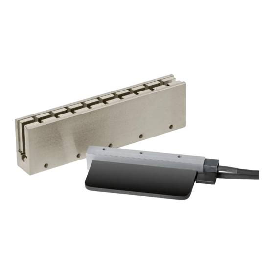
1.1 Servomotor Part Names 1.1.1 SGLG Servomotors Servomotor Part Names 1.1.1 SGLG Servomotors Nameplate Winding section Magnetic Way Nameplate Base Moving Coil Enclosed cable (Sensor Cable) Polarity Sensor (Hall Sensor) Enclosed cable (Servomotor Main Circuit Cable) 1.1.2 SGLF Servomotors Moving Coil Enclosed cable (Sensor Cable) Dummy plate to... -
Page 32: Interpreting The Nameplates
1.2 Interpreting the Nameplates 1.2.1 Moving Coils Interpreting the Nameplates The following basic information is provided on the nameplate. 1.2.1 Moving Coils LINEAR SERVO MOTOR Moving Coil SGLFW2−45A200AS model Ins. 1120 UL/TUV Rated output, power supply voltage, rated current, and thermal class Rated/Max. -
Page 33: Outline Of Model Designations
1.3 Outline of Model Designations 1.3.1 Servomotors Outline of Model Designations 1.3.1 Servomotors This section outlines the model numbers of Σ-7-Series Servomotors. For details, refer to the chapter for your type of Servomotor. 30 A 050 C P Series 3rd digit on digit digit Σ-7-Series Servomotors... -
Page 34: Combinations Of Servomotors And Servopacks
1.4 Combinations of Servomotors and SERVOPACKs Combinations of Servomotors and SERVOPACKs Instanta- SERVOPACK Model neous Rated Maxi- Linear Servomotor Model Force SGD7W- SGD7S- SGD7C- Force SGLGW-30A050C 12.5 R70A or R70F SGLGW-30A080C R90A or R90F 1R6A SGLGW-40A140C SGLGW-40A253C 1R6A or 2R1F SGLG SGLGW-40A365C... - Page 35 1.4 Combinations of Servomotors and SERVOPACKs Continued from previous page. Instanta- SERVOPACK Model neous Rated Maxi- Linear Servomotor Model Force SGD7W- SGD7S- SGD7C- Force SGLTW-20A170A 3R8A 5R5A SGLTW-20A320A 7R6A − SGLTW-20A460A 1140 120A SGLTW-35A170A 5R5A SGLTW-35A170H SGLTW-35A320A 1320 120A SGLT...
-
Page 36: Capacity Selection
Capacity Selection This chapter describes calculation methods to use when selecting Servomotor capacities. Selecting the Servomotor Capacity ..2-2... -
Page 37: Selecting The Servomotor Capacity
2.1 Selecting the Servomotor Capacity Selecting the Servomotor Capacity Contact your Yaskawa representative for information on the Servomotor capacity selection soft- ware. Refer to the following selection examples to select Servomotor capacities with manual calculations. Mechanical Specifications Load Table Moving Coil... - Page 38 2.1 Selecting the Servomotor Capacity Specifications of the Provisionally Selected Servomotor Item Value Maximum Force 440 (N) Rated Force 140 (N) Moving Coil Mass (m 0.82 (kg) Servomotor Magnetic Attraction (F 0 (N) Verification of the Provisionally Selected Servomotor •...
-
Page 39: Specifications, Ratings, And External Dimensions Of Sglg Servomotors
Specifications, Ratings, and External Dimensions of SGLG Servomotors This chapter describes how to interpret the model numbers of SGLG Servomotors and gives their specifications, rat- ings, and external dimensions. Model Designations ....3-2 3.1.1 Moving Coil . -
Page 40: Model Designations
3.1 Model Designations 3.1.1 Moving Coil Model Designations 3.1.1 Moving Coil S G L G W - 30 A 050 C P - E 10th 11th 12th 3rd+4th 6th+7th+8th Linear Series digit digit digit digit digit digit digit digits digits Linear Servomotors... -
Page 41: Magnetic Way
3.1 Model Designations 3.1.2 Magnetic Way 3.1.2 Magnetic Way S G L G M - 30 108 A 3rd+4th 5th+6th+7th Linear Σ Series digit digit digit digit digits digits Linear Servomotors Length of 1st digit 5th+6th+7th digits Servomotor Type 9th digit Options Magnetic Way... -
Page 42: Precautions On Moving Coils With Polarity Sensors (Hall Sensors)
3.1 Model Designations 3.1.3 Precautions on Moving Coils with Polarity Sensors (Hall Sensors) 3.1.3 Precautions on Moving Coils with Polarity Sensors (Hall Sensors) When you use a Moving Coil with a Polarity Sensor (Hall Sensor), the Magnetic Way must cover the bottom of the polarity sensor (hall sensor). -
Page 43: Ratings And Specifications
3.2 Ratings and Specifications 3.2.1 Specifications: With Standard-Force Magnetic Way Ratings and Specifications 3.2.1 Specifications: With Standard-Force Magnetic Way Linear Servomotor Moving Coil Model 050C 080C 140C 253C 365C 140C 253C 365C 200C 370C 535C SGLGW- Time Rating Continuous Thermal Class Insulation Resistance 500 VDC, 10 MΩ... -
Page 44: Ratings: With Standard-Force Magnetic Way
3.2 Ratings and Specifications 3.2.2 Ratings: With Standard-Force Magnetic Way 3.2.2 Ratings: With Standard-Force Magnetic Way Linear Servomotor Moving Coil Model SGLGW- 050C 080C 140C 253C 365C 140C 253C 365C 200C 370C 535C Rated Motor Speed (Refer- ence Speed during Speed Control) Maximum Speed... -
Page 45: Force-Motor Speed Characteristics
3.2 Ratings and Specifications 3.2.3 Force-Motor Speed Characteristics 3.2.3 Force-Motor Speed Characteristics Continuous duty zone (solid lines): With three-phase 200-V input Intermittent duty zone (dotted lines): With single-phase 200-V input (dashed-dotted lines): With single-phase 100-V input SGLGW-30A050C* SGLGW-30A080C* Force (N) Force (N) SGLGW-40A140C SGLGW-40A253C... -
Page 46: Servomotor Overload Protection Characteristics
3.2 Ratings and Specifications 3.2.4 Servomotor Overload Protection Characteristics 3.2.4 Servomotor Overload Protection Characteristics The overload detection level is set for hot start conditions with a Servomotor surrounding air tem- perature of 40°C. SGLGW-30A SGLGW-40A 10000 10000 1000 1000 Force reference (percent of rated force) Force reference (percent of rated force) SGLGW-90A SGLGW-60A... -
Page 47: Specifications: With High-Force Magnetic Way
3.2 Ratings and Specifications 3.2.5 Specifications: With High-Force Magnetic Way 3.2.5 Specifications: With High-Force Magnetic Way Linear Servomotor Moving Coil Model SGLGW- 140C 253C 365C 140C 253C 365C Time Rating Continuous Thermal Class Insulation Resistance 500 VDC, 10 MΩ min. Withstand Voltage 1,500 VAC for 1 minute Excitation... -
Page 48: Force-Motor Speed Characteristics
3.2 Ratings and Specifications 3.2.7 Force-Motor Speed Characteristics Continued from previous page. Linear Servomotor Moving Coil Model SGLGW- 140C 253C 365C 140C 253C 365C Combined Magnetic Way, SGLGM- Combined Serial Converter Unit, JZDP- - 1R6A, 2R8A, 1R6A, SGD7S- 3R8A... -
Page 49: Servomotor Overload Protection Characteristics
3.2 Ratings and Specifications 3.2.8 Servomotor Overload Protection Characteristics 3.2.8 Servomotor Overload Protection Characteristics The overload detection level is set for hot start conditions with a Servomotor surrounding air tem- perature of 40°C. SGLGW-40A with High-Force Magnetic Way SGLGW-60A with High-Force Magnetic Way 10000 10000 1000... -
Page 50: External Dimensions
3.3 External Dimensions 3.3.1 SGLGW-30 External Dimensions 3.3.1 SGLGW-30 Moving Coils: SGLGW-30AC × × 2 × #4-40 UNC screws Cable The Moving Coil moves in the direction indicated by the arrow UL20276, when current flows in the following phase sequence: U, V, W. Cable AWG26 UL2517, AWG25... - Page 51 3.3 External Dimensions 3.3.1 SGLGW-30 Moving Coils: SGLGW-30ACD 4 × M4 × 5 2 × #4-40 UNC screws The Moving Coil moves in the direction indicated by the Cable arrow when current flows in the following phase sequence: UL20276, U, V, W.
- Page 52 3.3 External Dimensions 3.3.1 SGLGW-30 Standard-Force Magnetic Ways: SGLGM-30A Pitch: 54 N × 4.5 dia. (18) 8 dia. L1 (1 unit) × × Pitch: 54 (27) Unit: mm Magnetic Way Model Approx. Mass [kg] SGLGM- -0.1 30108A -0.3 30216A -0.1 -0.3 -0.1...
-
Page 53: Sglgw-60
3.3 External Dimensions 3.3.2 SGLGW-40 3.3.2 SGLGW-40 Moving Coils: SGLGW-40AC 2 × #4-40 UNC screws × × The Moving Coil moves in the direction indicated by the arrow when current flows in the following phase sequence: U, V, W. (5.3 dia.) 25.4 (7 dia.) -
Page 54: Sglgw-40
3.3 External Dimensions 3.3.2 SGLGW-40 Moving Coils: SGLGW-40ACD 2 × #4-40 UNC screws × × The Moving Coil moves in the direction indicated by the arrow when current flows in the following phase sequence: U, V, W. (5.3 dia.) 25.4 (7 dia.) N1 ×... - Page 55 3.3 External Dimensions 3.3.2 SGLGW-40 Standard-Force Magnetic Ways: SGLGM-40C (without Mounting Holes on the Bottom) SGLGM-40CT (with Mounting Holes on the Bottom) L1 (1 unit) Pitch: 45 12.7 25.4 (22.5) 22.5 25.4 N × 5.5 dia. 10 dia. 22.5 (22.5) Pitch: 45 ...
- Page 56 3.3 External Dimensions 3.3.2 SGLGW-40 High-Force Magnetic Ways: SGLGM-40C-M (without Mounting Holes on the Bottom) SGLGM-40CT-M (with Mounting Holes on the Bottom) L1 (1 unit) 12.2 12.2 Pitch: 45 15.9 31.8 22.5 (22.5) 31.8 N × 5.5 dia. 10 dia. (22.5) 22.5 Pitch: 45...
- Page 57 3.3 External Dimensions 3.3.3 SGLGW-60 3.3.3 SGLGW-60 Moving Coils: SGLGW-60A C × #4-40 UNC screws × × The Moving Coil moves in the direction indicated by the arrow when current flows in the following phase sequence: U, V, W. (5.3 dia.) (7 dia.) 25.4...
-
Page 58: Sglgw-60
3.3 External Dimensions 3.3.3 SGLGW-60 Moving Coils: SGLGW-60ACD × #4-40 UNC screws × × The Moving Coil moves in the direction indicated by the arrow when current flows in the following phase sequence: U, V, W. (5.3 dia.) 25.4 (7 dia.) N1 ×... - Page 59 3.3 External Dimensions 3.3.3 SGLGW-60 Standard-Force Magnetic Ways: SGLGM-60C (without Mounting Holes on the Bottom) SGLGM-60CT (with Mounting Holes on the Bottom) L1 (1 unit) Pitch: 45 12.7 25.4 (22.5) 22.5 25.4 N × 5.5 dia. 10 dia. (22.5) 22.5 Pitch: 45 SGLGM-...
- Page 60 3.3 External Dimensions 3.3.3 SGLGW-60 High-Force Magnetic Ways: SGLGM-60C-M (without Mounting Holes on the Bottom) SGLGM-60CT-M (with Mounting Holes on the Bottom) L1 (1 unit) 12.2 12.2 Pitch: 45 15.9 31.8 (22.5) 22.5 31.8 N × 5.5 dia. 10 dia. (22.5) 22.5 Pitch: 45...
-
Page 61: Sglgw-90
3.3 External Dimensions 3.3.4 SGLGW-90 3.3.4 SGLGW-90 Moving Coils: SGLGW-90AC × × 2 × #4-40 UNC screws 2 × N1 × M6 × 9 (both sides) Cable UL20276, AWG26 The Moving Coil moves in the direction indicated by the arrow when current flows in the following phase sequence: U, V, W. - Page 62 3.3 External Dimensions 3.3.4 SGLGW-90 Standard-Force Magnetic Ways: SGLGM-90A L1 (1 unit) 13.8 18.5 Pitch: 63 50.8 (31.5) 31.5 N × 6.6 dia. 12 dia. (44) Pitch: 63 × × 14.5 Unit: mm Magnetic Way Model Approx. Mass [kg] SGLGM- -0.1 90252A...
-
Page 63: Selecting Cables
CN2 and Serial Converter Unit) Linear Servomotor Main Circuit Cable Serial Converter Unit Linear Encoder Cable Linear encoder (Not provided by Yaskawa.) Sensor Cable (between Serial Converter Unit and polarity sensor (hall sensor)) Polarity sensor (hall sensor) Linear Servomotor You can connect directly to an absolute linear encoder. - Page 64 3.4 Selecting Cables 3.4.1 Cable Configurations Linear Servomotor Main Circuit Cables Length Linear Servomotor Model Order Number Appearance JZSP-CLN11-01-E JZSP-CLN11-03-E SERVOPACK end Linear Servomotor JZSP-CLN11-05-E SGLGW-30A, -40A, -60A 10 m JZSP-CLN11-10-E 15 m JZSP-CLN11-15-E 20 m JZSP-CLN11-20-E JZSP-CLN21-01-E JZSP-CLN21-03-E SERVOPACK end Linear Servomotor JZSP-CLN21-05-E...
- Page 65 Specifications, Ratings, and External Dimensions of SGLF Servomotors This chapter describes how to interpret the model numbers of SGLF Servomotors and gives their specifications, rat- ings, and external dimensions. Model Designations ....4-3 4.1.1 SGLFW2 Models .
- Page 66 External Dimensions ....4-17 4.4.1 SGLFW2-30 ......4-17 4.4.2 SGLFW2-45 .
-
Page 67: Model Designations
4.1 Model Designations 4.1.1 SGLFW2 Models Model Designations 4.1.1 SGLFW2 Models Moving Coil S G L F W 2 - 30 A 070 A T 1 H 10th 11th 12th 6th+7th+8th 3rd+4th Linear Series digit digit digit digit digit digit digits... -
Page 68: Sglfw Models
4.1 Model Designations 4.1.2 SGLFW Models 4.1.2 SGLFW Models Moving Coil S G L F W - 20 A 090 A P - E 10th 11th 12th 6th+7th+8th 3rd+4th Linear Series digit digit digit digit digit digit digits digit digits... -
Page 69: Precautions On Moving Coils With Polarity Sensors (Hall Sensors)
4.1 Model Designations 4.1.3 Precautions on Moving Coils with Polarity Sensors (Hall Sensors) 4.1.3 Precautions on Moving Coils with Polarity Sensors (Hall Sensors) When you use a Moving Coil with a Polarity Sensor (Hall Sensor), the Magnetic Way must cover the bottom of the polarity sensor (hall sensor). -
Page 70: Ratings And Specifications: Sglfw2 Models
4.2 Ratings and Specifications: SGLFW2 Models 4.2.1 Specifications Ratings and Specifications: SGLFW2 Models 4.2.1 Specifications Linear Servomotor Moving Coil Model SGLFW2- 070A 120A 230A 200A 380A 200A 380A 560A 380A 560A Time Rating Continuous Thermal Class Insulation Resistance 500 VDC, 10 MΩ min. Withstand Voltage 1,500 VAC for 1 minute Excitation... -
Page 71: Ratings: Self-Cooled Models
4.2 Ratings and Specifications: SGLFW2 Models 4.2.2 Ratings: Self-Cooled Models 4.2.2 Ratings: Self-Cooled Models Linear Servomotor Moving Coil Model SGLFW2- 070A 1 120A 230A 200A 380A Rated Motor Speed (Reference Speed during Speed Control) Maximum Speed *1, *2 Rated Force 1680... - Page 72 4.2 Ratings and Specifications: SGLFW2 Models 4.2.2 Ratings: Self-Cooled Models Linear Servomotor Moving Coil Model SGLFW2- 200A 380A 560A 380A 560A Rated Motor Speed (Reference Speed during Speed Control) Maximum Speed *1, *2 1120 1680 1680 2520 Rated Force...
-
Page 73: Force-Motor Speed Characteristics: Self-Cooled Models
4.2 Ratings and Specifications: SGLFW2 Models 4.2.3 Force-Motor Speed Characteristics: Self-Cooled Models 4.2.3 Force-Motor Speed Characteristics: Self-Cooled Models Continuous duty zone (solid lines): With three-phase 200-V input Intermittent duty zone (dotted lines): With single-phase 200-V input (dashed-dotted lines): With single-phase 100-V input SGLFW2-30A120A 1 SGLFW2-30A070A 1 Force (N) -
Page 74: Ratings: Water-Cooled Models
4.2 Ratings and Specifications: SGLFW2 Models 4.2.4 Ratings: Water-Cooled Models 4.2.4 Ratings: Water-Cooled Models Linear Servomotor Moving Coil Model SGLFW2- 200A Rated Motor Speed (Reference Speed during Speed Control) Maximum Speed *1, *2 Rated Force 1680 Maximum Force Arms 11.5 Rated Current Arms... -
Page 75: Force-Motor Speed Characteristics: Water-Cooled Models
4.2 Ratings and Specifications: SGLFW2 Models 4.2.5 Force-Motor Speed Characteristics: Water-Cooled Models 4.2.5 Force-Motor Speed Characteristics: Water-Cooled Models Continuous duty zone (solid lines): With three-phase 200-V input Intermittent duty zone (dotted lines): With single-phase 200-V input SGLFW2-90A200AL 1000 1500 2000 Force (N) Note: 1.These values are for operation in combination with a SERVOPACK when the temperature of the armature winding is 100°C. -
Page 76: Servomotor Overload Protection Characteristics
4.2 Ratings and Specifications: SGLFW2 Models 4.2.6 Servomotor Overload Protection Characteristics 4.2.6 Servomotor Overload Protection Characteristics The overload detection level is set for hot start conditions with a Servomotor surrounding air tem- perature of 40°C. SGLFW2-30A070A SGLFW2-30A120A and -230A 10000 10000 1000 1000... -
Page 77: Ratings And Specifications: Sglfw Models
4.3 Ratings and Specifications: SGLFW Models 4.3.1 Specifications Ratings and Specifications: SGLFW Models 4.3.1 Specifications Linear Servomotor Moving Coil Model SGLFW- 090A 120A 120A 230A 200B 380B 200B 380B Time Rating Continuous Thermal Class Insulation Resistance 500 VDC, 10 MΩ min. Withstand Voltage 1,500 VAC for 1 minute Excitation... -
Page 78: Ratings
4.3 Ratings and Specifications: SGLFW Models 4.3.2 Ratings 4.3.2 Ratings Linear Servomotor Moving Coil Model SGLFW- 090A 120A 120A 230A 200B 380B 200B 380B Rated Motor Speed (Reference Speed during Speed Control) Maximum Speed *1, *2 1120 Rated Force 1200 1200 2400 Maximum Force... -
Page 79: Force-Motor Speed Characteristics
4.3 Ratings and Specifications: SGLFW Models 4.3.3 Force-Motor Speed Characteristics 4.3.3 Force-Motor Speed Characteristics Continuous duty zone (solid lines): With three-phase 200-V input Intermittent duty zone (dotted lines): With single-phase 200-V input (dashed-dotted lines): With single-phase 100-V input SGLFW-35A120A SGLFW-20A090A SGLFW-20A120A 0 20 40 60 80 100 120 140 Force (N) -
Page 80: Servomotor Overload Protection Characteristics
4.3 Ratings and Specifications: SGLFW Models 4.3.4 Servomotor Overload Protection Characteristics 4.3.4 Servomotor Overload Protection Characteristics The overload detection level is set for hot start conditions with a Servomotor surrounding air tem- perature of 40°C. SGLFW-20A SGLFW-35A 10000 10000 1000 1000 50 100 150 200 250 300... -
Page 81: External Dimensions
4.4 External Dimensions 4.4.1 SGLFW2-30 External Dimensions 4.4.1 SGLFW2-30 Moving Coil with Polarity Sensor (Hall Sensor): SGLFW2-30A070AS Polarity sensor 50 min. (hall sensor) 12.2 40 0.1 (12) Magnetic Way (27.5) Thermal protector relay connector (Molex Japan LLC) Receptacle housing: 5557-02R Plug housing: 5559-02P Polarity sensor (hall sensor) and thermal protector cable... -
Page 82: Sglfw2-30
4.4 External Dimensions 4.4.1 SGLFW2-30 Moving Coils with Polarity Sensors (Hall Sensors): SGLFW2-30AAS Polarity sensor 50 min. (hall sensor) 12.6 400.1 Thermal protector relay Magnetic Way (33.2) 26.7 connector (Molex Japan LLC) (27.5) 1.5 Receptacle housing: 5557-02R Plug housing: 5559-02P Polarity sensor (hall sensor) and thermal protector cable UL20276, AWG28... - Page 83 4.4 External Dimensions 4.4.1 SGLFW2-30 Moving Coil without Polarity Sensor (Hall Sensor): SGLFW2-30A070AT 12.2 40±0.1 Magnetic Way (12) (27.5) 50 min. Servomotor Main Circuit Cable UL2586, AWG19 Refer to the following figure . (10.2) 29±0.1 Thermal protector cable UL1333, AWG20 Gap 0.8 The Moving Coil moves in the direction indicated by the arrow...
- Page 84 4.4 External Dimensions 4.4.1 SGLFW2-30 Moving Coils without Polarity Sensors (Hall Sensors): SGLFW2- 30AAT 40±0.1 Magnetic Way (33.2) 12.6 26.7 (27.5) 50 min. Servomotor Main Circuit Cable and . Refer to the following figures UL2586, AWG19 Thermal protector cable (10.2) 29±0.1 The Moving Coil moves in the direction...
- Page 85 4.4 External Dimensions 4.4.1 SGLFW2-30 Magnetic Ways: SGLFM2-30A 2 × N, 4.8-dia. mounting holes 8.5 dia. (45) (Reference mark) 10.2±0.1 22.5±0.1 (22.5) L1±0.1 Reference mark (There are two, approx. 4-dia. indentations.) Height of screw head: 4.2 max. Mounting Section Details Unit: mm Note: More than one Magnetic Way can be connected.
-
Page 86: Sglfw2-45
4.4 External Dimensions 4.4.2 SGLFW2-45 4.4.2 SGLFW2-45 Moving Coils with Polarity Sensors (Hall Sensors): SGLFW2-45AAS Thermal protector relay connector (Molex Japan LLC) Polarity sensor(hall sensor) and Receptacle housing: 5557-02R thermal protector cable Plug housing: 5559-02P Polarity sensor (hall sensor) UL20276, AWG28 50 min. - Page 87 4.4 External Dimensions 4.4.2 SGLFW2-45 Moving Coils without Polarity Sensors (Hall Sensors): SGLFW2- 45AAT 500.1 48.5 (55) (36) 50 min. Magnetic Way Refer to the following figures and . Servomotor Main Circuit Cable UL2586, AWG15 (11.2) 380.1 Refer to the following table. Thermal protector cable The Moving Coil moves in the direction UL1333, AWG20...
-
Page 88: 4.4 External Dimensions
4.4 External Dimensions 4.4.2 SGLFW2-45 Magnetic Ways: SGLFM2-45A 2 × N, 5.8-dia. mounting holes 10 dia. (102) 11.2±0.1 51±0.1 (51) (Reference mark) L1±0.1 Reference mark (There are two, approx. 4-dia. indentations.) Height of screw head: 5.2 max. Mounting Section Details Unit: mm Note: More than one Magnetic Way can be connected. -
Page 89: Sglfw2-90: Self-Cooled Models
4.4 External Dimensions 4.4.3 SGLFW2-90: Self-Cooled Models 4.4.3 SGLFW2-90: Self-Cooled Models Moving Coils with Polarity Sensors (Hall Sensors): SGLFW2- 90AAS1 50 min. Thermal protector relay connector (Molex Japan LLC) Receptacle housing: 5557-02R Polarity sensor 48.5 (55) Plug housing: 5559-02P (hall sensor) 50±0.1 Refer to the following table. - Page 90 4.4 External Dimensions 4.4.3 SGLFW2-90: Self-Cooled Models Connector Specifications Polarity Sensor (Hall Sensor) Output Signal • Servomotor Connector The figure on the right shows the relationship between the Phase U Su, Sv, and Sw polarity sen- Phase V White sor (hall sensor) output sig- Phase W...
- Page 91 4.4 External Dimensions 4.4.3 SGLFW2-90: Self-Cooled Models Moving Coil Model Approx. Mass Flatness SGLFW2- [kg] 300 ±30 90A200AT1 89.5 500 ±50 90A200AT1H 300 ±30 90A380AT1 268.5 365.5 10.1 500 ±50 90A380AT1H 300 ±30 90A560AT1 447.5 14.9 500 ±50 90A560AT1H Connector Specifications •...
-
Page 92: Sglfw2-90: Water-Cooled Models
4.4 External Dimensions 4.4.4 SGLFW2-90: Water-Cooled Models 4.4.4 SGLFW2-90: Water-Cooled Models Contact your Yaskawa representative for information on the SGLFW2-90A380AL and - 90A560AL. Moving Coils with Polarity Sensors (Hall Sensors): SGLFW2- 90A200ASL 50 min. Polarity Sensor 65±0.1 (Hall Sensor) -
Page 93: 4.4.4 Sglfw2-90: Water-Cooled Models
4.4 External Dimensions 4.4.4 SGLFW2-90: Water-Cooled Models Moving Coils without Polarity Sensors (Hall Sensors): SGLFW2- 90A200ATL 65±0.1 (39) Magnetic Way 2 × RC 1/8 (for cooling medium)* 60 min. 6 × M6 × 11.5 (11.2) 53±0.1 Thermal protector cable Gap 0.8 UL1333, AWG20 Thermal protector connector... -
Page 94: Sglfw2-90: Self-Cooled And Water-Cooled Models
4.4 External Dimensions 4.4.5 SGLFW2-90: Self-Cooled and Water-Cooled Models 4.4.5 SGLFW2-90: Self-Cooled and Water-Cooled Models Magnetic Ways: SGLFM2-90A 2 × N, 7-dia. mounting holes 11.5 dia. (102) 51±0.1 11.2±0.1 (51) (Reference mark) L1±0.1 Reference mark (There are two, approx. 4-dia. indentations.) Height of screw head: 6.7 max. -
Page 95: Sglfw2-1D
4.4 External Dimensions 4.4.6 SGLFW2-1D 4.4.6 SGLFW2-1D Moving Coil with Polarity Sensor (Hall Sensor): SGLFW2-1DAAS1 Thermal protector relay connector (Molex Japan LLC) Receptacle housing: 5557-02R Plug housing: 5559-02P 50 min. Polarity sensor 50±0.1 48.5 (55) (hall sensor) Refer to the fol l o wi n g tabl e . (36) Magnetic Way Polarity sensor... - Page 96 4.4 External Dimensions 4.4.6 SGLFW2-1D Moving Coil without Polarity Sensor (Hall Sensor): SGLFW2-1DAAT1 50±0.1 Refer to the following table. (55) 48.5 Magnetic Way (36) Servomotor Main Circuit Cable UL2586, AWG12 60 min. and . Refer to the following figures (11.2) 38±0.1 Thermal protector cable...
- Page 97 4.4 External Dimensions 4.4.6 SGLFW2-1D Magnetic Ways: SGLFM2-1DA 2 × N, 10-dia. mounting holes 15 dia. (102) 11.2±0.1 51±0.1 (51) (Reference L1±0.1 mark) Reference mark (There are two, approx. 4-dia. indentations.) Height of screw head: 8.2 max. Mounting Section Details Unit: mm Note: More than one Magnetic Way can be connected.
-
Page 98: Sglfw-20
4.4 External Dimensions 4.4.7 SGLFW-20 4.4.7 SGLFW-20 Moving Coils: SGLFW-20AA 50 min. (25) Polarity sensor (hall sensor) (32) Magnetic Way The Moving Coil moves in (4.2 with magnet cover) the direction indicated by Refer to the (4 without magnet cover) the arrow when current flows in 2 ×... - Page 99 4.4 External Dimensions 4.4.7 SGLFW-20 Magnetic Ways: SGLFM-20A (L3) Moving Coil 9.9° 2 × N × 4.8 dia. (Reference mark) Reference mark (34) (54) (30.8) (Gap: 1) 45±0.1 Reference mark (There are two, approx. 4-dia. indentations.) Unit: mm Height of screw head: 4.2 max. Mounting Section Details Note: More than one Magnetic Way can be connected.
-
Page 100: Sglfw-35
4.4 External Dimensions 4.4.8 SGLFW-35 4.4.8 SGLFW-35 Moving Coils: SGLFW-35AA 50 min. (32) Polarity sensor Magnetic Way (hall sensor) (4.2 with magnet cover) (4 without magnet cover) Refer to the following 2 #4-40 UNC and . Refer to the following table. figures screws 30 min. - Page 101 4.4 External Dimensions 4.4.8 SGLFW-35 Moving Coils: SGLFW-35AAD 50 min. Polarity sensor (32) Magnetic Way (Hall sensor) (4.2 with magnet cover) (4 without magnet cover) and . Refer to the following figures Refer to the following table. 2 × #4-40 UNC screws 450.1 (Gap: 0.8 with magnet cover)
-
Page 102: Sglfw-35
4.4 External Dimensions 4.4.8 SGLFW-35 Magnetic Ways: SGLFM-35 A (L3) 2 × N × 4.8 dia. Moving Coil (Reference mark) Reference mark (54) (34) (32.2) (Gap: 1) 45±0.1 Reference mark (There are two, approx. 4-dia. indentations.) Unit: mm Height of screw head: 4.2 max. - Page 103 4.4 External Dimensions 4.4.9 SGLFW-50 4.4.9 SGLFW-50 Moving Coils: SGLFW-50AB 50 min. (40) Polarity sensor Magnetic Way (hall sensor) (4.2 with magnet cover) Refer to the following figures and . (4 without magnet cover) 50 min. Refer to the following table. 580.1 (Gap: 0.8 with magnet cover) The Moving Coil moves in the direction indicated...
-
Page 104: Sglfw-50
4.4 External Dimensions 4.4.9 SGLFW-50 Moving Coils: SGLFW-50ABD 50 min. (40) Polarity sensor Magnetic Way (hall sensor) Refer to the following figures and . Refer to the following table. 50 min. (4.2 with magnet cover) (4 without magnet cover) 580.1 (Gap: 0.8 with magnet cover) The Moving Coil moves in the direction indicated... - Page 105 4.4 External Dimensions 4.4.9 SGLFW-50 Magnetic Ways: SGLFM-50A (L3) 8.6° Moving Coil 2 × N × 5.8 dia. Reference mark (43) (67.5) (Reference 67.5 mark) (39.4) (Gap: 1) 58±0.1 Reference mark (There are two, approx. 4-dia. indentations.) Unit: mm Height of screw head: 5.2 max.
-
Page 106: 4.4.10 Sglfw-1Z
4.4 External Dimensions 4.4.10 SGLFW-1Z 4.4.10 SGLFW-1Z Moving Coils: SGLFW-1ZAB 50 min. Polarity sensor (40) Magnetic Way (hall sensor) 2 × #4-40 UNC screws The Moving Coil moves in the direction Refer to the following indicated by the arrow when current flows ... - Page 107 4.4 External Dimensions 4.4.10 SGLFW-1Z Moving Coils: SGLFW-1ZA200BD 50 min. Polarity sensor 120 (60 × 2) Magnetic Way (hall sensor) (40) Proximity sensor (Hall sensor) cable UL20276, AWG28 2 × #4-40 UNC The Moving Coil moves in the screws Refer to the direction indicated by the arrow when current flows in the following phase...
- Page 108 4.4 External Dimensions 4.4.10 SGLFW-1Z Magnetic Ways: SGLFM-1ZA (L3) 2 × N, 7-dia. mounting holes Moving Coil 11.5 dia. (Reference (43) 67.5 (67.5) Reference mark mark) (43.2) (Gap1) 58±0.1 Reference mark (There are two, approx. 4-dia. indentations.) Height of screw head: 6.7 max. Unit: mm Mounting Section Details Note: More than one Magnetic Way can be connected.
-
Page 109: Selecting Cables
Linear Encoder Cable Sensor Cable Linear Encoder (between Serial Converter Unit and polarity sensor (Not provided by Yaskawa.) (hall sensor)) Polarity sensor (hall sensor) Linear Servomotor * You can connect directly to an absolute linear encoder. Note: Refer to the following manual for the following information. -
Page 110: Linear Servomotor Main Circuit Cables
4.5 Selecting Cables 4.5.2 Linear Servomotor Main Circuit Cables 4.5.2 Linear Servomotor Main Circuit Cables Length Linear Servomotor Model Order Number Appearance JZSP-CLN11-01-E JZSP-CLN11-03-E SERVOPACK end Linear Servomotor JZSP-CLN11-05-E SGLFW-20A, -35A 10 m JZSP-CLN11-10-E 15 m JZSP-CLN11-15-E 20 m JZSP-CLN11-20-E JZSP-CLN21-01-E JZSP-CLN21-03-E SERVOPACK end... - Page 111 4.5 Selecting Cables 4.5.2 Linear Servomotor Main Circuit Cables Continued from previous page. Length Linear Servomotor Model Order Number Appearance JZSP-CLN423-01-E JZSP-CLN423-03-E SERVOPACK end Linear Servomotor end JZSP-CLN423-05-E SGLFW2-90A200A 10 m JZSP-CLN423-10-E 15 m JZSP-CLN423-15-E 20 m JZSP-CLN423-20-E Note: Estimates are available for models other than those listed above (SGLFW2-90AAL and SGLFW2- 1DAL).
-
Page 112: Specifications, Ratings, And External Dimensions Of Sglt Servomotors
Specifications, Ratings, and External Dimensions of SGLT Servomotors This chapter describes how to interpret the model numbers of SGLT Servomotors and gives their specifications, rat- ings, and external dimensions. Model Designations ....5-2 5.1.1 Moving Coil . -
Page 113: Model Designations
None Not certified * Contact your Yaskawa representative for the characteristics, dimensions, and other details on Servomotors with these specifications. Note: This information is provided to explain model numbers. It is not meant to imply that models are available for all... -
Page 114: Magnetic Way
5.1 Model Designations 5.1.2 Magnetic Way 5.1.2 Magnetic Way T M - 20 324 A S G L 3rd+4th 5th+6th+7th Linear Series digit digit digit digit digits digits Linear Servomotors Length of 1st digit 9th digit 5th+6th+7th digits Options Servomotor Type Magnetic Way... -
Page 115: Precautions On Moving Coils With Polarity Sensors (Hall Sensor)
5.1 Model Designations 5.1.3 Precautions on Moving Coils with Polarity Sensors (Hall Sensor) 5.1.3 Precautions on Moving Coils with Polarity Sensors (Hall Sensor) When you use a Moving Coil with a Polarity Sensor (Hall Sensor), the Magnetic Way must cover the bottom of the polarity sensor (hall sensor). -
Page 116: Ratings And Specifications
5.2 Ratings and Specifications 5.2.1 Specifications Ratings and Specifications 5.2.1 Specifications Standard Models High-efficiency Models Linear Servomotor Moving Coil Model SGLTW- 170A 320A 460A 170A 320A 460A 400B 600B 400B 600B 170H 320H 170H 320H Time Rating Continuous Thermal Class Insulation Resistance 500 VDC, 10 MΩ... -
Page 117: Ratings
5.2 Ratings and Specifications 5.2.2 Ratings 5.2.2 Ratings High-efficiency Standard Models Models Linear Servomotor Moving Coil Model SGLTW- 170A 320A 460A 170A 320A 460A 400B 600B 400B 600B 170H 320H 170H 320H Rated Motor Speed (Reference Speed during Speed Control) Maximum Speed *1, *2... -
Page 118: Force-Motor Speed Characteristics
5.2 Ratings and Specifications 5.2.3 Force-Motor Speed Characteristics 5.2.3 Force-Motor Speed Characteristics Continuous duty zone (solid lines): With three-phase 200-V input Intermittent duty zone (dotted lines): With single-phase 200-V input Standard Models SGLTW-20A170A SGLTW-20A460A SGLTW-20A320A 200 400 600 800 1000 1200 Force (N) Force (N) Force (N) - Page 119 5.2 Ratings and Specifications 5.2.3 Force-Motor Speed Characteristics High-efficiency Models SGLTW-35A170H SGLTW-35A320H SGLTW-50A170H SGLTW-50A320H 1200 1200 1800 Force (N) Force (N) Force (N) Force (N) Note: 1.These values are for operation in combination with a SERVOPACK when the temperature of the armature winding is 100°C.
-
Page 120: Servomotor Overload Protection Characteristics
5.2 Ratings and Specifications 5.2.4 Servomotor Overload Protection Characteristics 5.2.4 Servomotor Overload Protection Characteristics The overload detection level is set for hot start conditions with a Servomotor surrounding air tem- perature of 40°C. SGLTW-20A A and -35A SGLTW-40A B and -80A 10000... -
Page 121: External Dimensions
5.3 External Dimensions 5.3.1 SGLTW-20: Standard Models External Dimensions 5.3.1 SGLTW-20: Standard Models Moving Coils: SGLTW-20AA × × (55) (L3) 47.5 Magnetic Way 2 × #4-40 UNC screws The Moving Coil moves in the direction Polarity sensor indicated by the arrow when current flows (hall sensor) in the following phase sequence: U, V, W. - Page 122 5.3 External Dimensions 5.3.1 SGLTW-20: Standard Models Magnetic Ways: SGLTM-20A (54) (55) (29.3) Moving Coil (54) ± (29.3) 2 N 7 dia. (Refer to Side-to-Side Cro Section for the depth.) Spacers: Do not remove them Side-to-Side Cross Section until the Moving Coil is mounted on the machine.
- Page 123 5.3 External Dimensions 5.3.1 SGLTW-20: Standard Models Magnetic Ways with Bases: SGLTM-20AY 11.7 (54) (70) (55) Base ± DATE (14) Moving Coil (162) 2 N2 10 dia. (Refer to Side-to-Side Cro Section for the depth.) Includes a 0.2-mm-thick ×...
-
Page 124: Sgltw-35: Standard Models
5.3 External Dimensions 5.3.2 SGLTW-35: Standard Models 5.3.2 SGLTW-35: Standard Models Moving Coils: SGLTW-35AA × × (70) (L3) Magnetic Way 2 #4-40 UNC screws The Moving Coil moves in the direction indicated by the arrow when current flows Polarity sensor ±... - Page 125 5.3 External Dimensions 5.3.2 SGLTW-35: Standard Models Magnetic Ways: SGLTM-35A (54) (70) (30.6) Moving Coil (54) ± 2 N 7 dia. (Refer to Side-to-Side Cro (30.6) Section for the depth.) Spacers: Do not remove Side-to-Side Cross Section them until the Moving Coil is ×...
- Page 126 5.3 External Dimensions 5.3.2 SGLTW-35: Standard Models Magnetic Ways with Bases: SGLTM-35AY (54) (85) (70) Base ± (14) Moving Coil (162) 2 N2 10 dia. (Refer to Side-to-Side Cro Section for the depth.) Includes a 0.2-mm-thick magnet cover. ×...
-
Page 127: Sgltw-35H: High-Efficiency Models
5.3 External Dimensions 5.3.3 SGLTW-35H: High-efficiency Models 5.3.3 SGLTW-35H: High-efficiency Models SGLTW-35H: High-efficiency Models × × (70) (L3) 62.5 Magnetic Way ± 0.15 Polarity sensor 2 #4-40 The Moving Coil moves in the Protective tube (hall sensor) direction indicated by the arrow UNC screws when current flows in the following phase sequence: U, V, W. - Page 128 5.3 External Dimensions 5.3.3 SGLTW-35H: High-efficiency Models Magnetic Ways: SGLTM-35H (54) (70) (30.6) Moving Coil (54) (30.6) 2 N 7 dia. (Refer to Side-to-Side Cro Section for the depth.) Spacers: Do not remove Includes a 0.2-mm-thick them until the Moving Coil is magnet cover.
-
Page 129: Sgltw-40: Standard Models
5.3 External Dimensions 5.3.4 SGLTW-40: Standard Models 5.3.4 SGLTW-40: Standard Models Moving Coils: SGLTW-40AB Polarity sensor (hall sensor) × × (83) Receptacle (L3) Magnetic Way 2 #4-40 The Moving Coil moves in the direction indicated by the arrow UNC screws 64 min. - Page 130 5.3 External Dimensions 5.3.4 SGLTW-40: Standard Models Magnetic Ways: SGLTM-40A (67.5) 67.5 (83) (36.1) Moving Coil 67.5 (67.5) ± 2 N 9 dia. (Refer to Side-to-Side Cro (36.1) Section for the depth.) (15) Spacers: Do not remove Side-to-Side Cross Section them until the Moving Coil is mounted on the machine.
- Page 131 5.3 External Dimensions 5.3.4 SGLTW-40: Standard Models Magnetic Ways with Bases: SGLTM-40AY 12.5 (67.5) 67.5 (103) (83) Base ± 92.5 (17.5) Moving Coil 92.5 (202.5) 2 × N2 × 12 dia. (Refer to the side cross-sectional view for the depth.) ×...
-
Page 132: Sgltw-50: High-Efficiency Models
5.3 External Dimensions 5.3.5 SGLTW-50: High-efficiency Models 5.3.5 SGLTW-50: High-efficiency Models Moving Coils: SGLTW-50AH × × (85) (L3) Magnetic Way 62.5 ± 0.15 The Moving Coil moves in the Polarity sensor 2 #4-40 Protective tube direction indicated by the arrow (hall sensor) when current flows in the following UNC screws... - Page 133 5.3 External Dimensions 5.3.5 SGLTW-50: High-efficiency Models Magnetic Ways: SGLTM-50H (54) (85) (27) (54) Moving Coil 2 N 7 dia. (Refer to Side-to-Side Cro Section for the depth.) Includes a 0.2-mm-thick Spacers: Do not remove magnet cover. them until the Moving Coil is mounted on the machine.
-
Page 134: Sgltw-80: Standard Models
5.3 External Dimensions 5.3.6 SGLTW-80: Standard Models 5.3.6 SGLTW-80: Standard Models Moving Coils: SGLTW-80 B × × Polarity sensor (hall sensor) (120) Receptacle (L3) Magnetic Way The Moving Coil moves in the direction indicated by the arrow 64 min. - Page 135 5.3 External Dimensions 5.3.6 SGLTW-80: Standard Models Magnetic Ways: SGLTM-80 (67.5) 67.5 (120) (37.9) Moving Coil 33.75 (67.5) ± (37.9) 2 × N2 × 9 dia. (Refer to Side-to-Side Cro Section for the depth.) (15) Side-to-Side Cross Section Spacers: Do not remove them until the Moving Coil is mounted on the machine.
- Page 136 5.3 External Dimensions 5.3.6 SGLTW-80: Standard Models Magnetic Ways with Bases: SGLTM-80 (67.5) 14.4 67.5 33.75 (140) (120) Moving Coil Base × × 12 dia. (Refer to Side-to-Side Cro Section for the depth.) ± 92.5 (17.5) 92.5 (202.5) ×...
-
Page 137: Selecting Cables
Sensor Cable (between Serial Converter Unit and Linear encoder polarity sensor (hall sensor)) (Not provided by Yaskawa.) Linear Servomotor Polarity sensor (hall sensor) * You can connect directly to an absolute linear encoder. Note: Refer to the following manual for the following information. -
Page 138: Linear Servomotor Main Circuit Cables
5.4 Selecting Cables 5.4.2 Linear Servomotor Main Circuit Cables 5.4.2 Linear Servomotor Main Circuit Cables Length Linear Servomotor Model Order Number Appearance JZSP-CLN21-01-E JZSP-CLN21-03-E SERVOPACK end Linear Servomotor JZSP-CLN21-05-E SGLTW-20A, -35A 10 m JZSP-CLN21-10-E 15 m JZSP-CLN21-15-E 20 m JZSP-CLN21-20-E JZSP-CLN14-01-E SERVOPACK end Linear Servomotor... - Page 139 5.4 Selecting Cables 5.4.2 Linear Servomotor Main Circuit Cables MS3106B22-2S: Straight Plug with Two-piece Shell Unit: mm 55.57 max. Joint Nut Length of Effective Joint Thread Outer Shell Size Joint Thread Length Diameter J ±0.12 W min. -0.38 1-3/8-18UNEF 18.26 40.48 9.53...
- Page 140 Equipment Design Precautions This chapter provides precautions for equipment design. Influence of Magnetic Attraction ..6-2 6.1.1 SGLF Servomotors ..... . . 6-2 6.1.2 SGLT Servomotors .
-
Page 141: Influence Of Magnetic Attraction
6.1 Influence of Magnetic Attraction 6.1.1 SGLF Servomotors Influence of Magnetic Attraction 6.1.1 SGLF Servomotors The Moving Coil and Magnetic Way face each other, so magnetic attraction will occur. Consider the following magnetic attractions when you design the equipment. Magnetic Attrac- Moving Coil Model Gap, G (mm) - Page 142 6.1 Influence of Magnetic Attraction 6.1.2 SGLT Servomotors 6.1.2 SGLT Servomotors The Magnetic Way tracks are located on both sides of the Moving Coil. If the gaps on both sides of the Moving Coil are the same, the magnetic attraction is canceled. However, it is diffi- cult to obtain the same gaps due to Servomotor precision, the precision of the user’s equip- ment, error when assembling the Servomotor, and other factors.
-
Page 143: Influence Of Magnetic Way Leakage Flux
6.2 Influence of Magnetic Way Leakage Flux 6.2.1 SGLG Servomotors Influence of Magnetic Way Leakage Flux The Magnetic Way has leakage flux. Particularly in locations where the leakage flux is 10 gauss or higher, the influence of the leakage flux will be strongly felt. Consider this in the equipment design. -
Page 144: Sglt Servomotors
6.2 Influence of Magnetic Way Leakage Flux 6.2.3 SGLT Servomotors 6.2.3 SGLT Servomotors Magnetic Way Location of 10-Gauss Leakage Flux Model X (mm) Y (mm) Z (mm) SGLTM- ... -
Page 145: Special Precautions For Sglt Servomotors
6.3 Special Precautions for SGLT Servomotors Special Precautions for SGLT Servomotors To mount the Magnetic Way, space is required between the Magnetic Way yoke and the posi- tioning ridges on the equipment. Design the equipment with the following recommended values (W2) for the positioning ridges on the equipment. -
Page 146: Precautions For Water-Cooled Models
6.4 Precautions for Water-Cooled Models Precautions for Water-Cooled Models SGLFW2 Servomotors (SGLFW2- ) use forced cooling with a cooling medium. Observe the following precautions if you use one of these Servomotors. Cooling System Design and Installation • You must design, purchase, and install the portion of the cooling system that is external to the Servomotor, such as the cooling medium, piping, and chiller or other cooling device. - Page 147 6.4 Precautions for Water-Cooled Models Pressure • Install a safety valve or other mechanism to keep the pressure in the Servomotor cooling pip- ing below 1.0 MPa. • The normal withstand pressure of the Servomotor is 0.5 MPa. Do not allow the pressure to increase even momentarily to greater than 1.0 MPa, e.g., for cooling medium surges.
- Page 148 Servomotor Installation This chapter describes the installation conditions, proce- dures, and precautions for Servomotors. Installation Conditions ....7-2 7.1.1 Installation Environment ....7-2 7.1.2 Installation Orientation .
-
Page 149: Installation Conditions
7.1 Installation Conditions 7.1.1 Installation Environment Installation Conditions The service life of a Servomotor will be shortened or unexpected problems will occur if the Ser- vomotor is installed incorrectly or in an inappropriate location. Always observe the following installation instructions. 7.1.1 Installation Environment Refer to the specifications for each type of Servomotor for the mechanical specifications, pro-... -
Page 150: Installation Procedure
7.2 Installation Procedure 7.2.1 SGLG Servomotors (Coreless Models) Installation Procedure 7.2.1 SGLG Servomotors (Coreless Models) Mounting the Magnetic Way The SGLG Magnetic Ways consist of C-shaped steel plates with magnets facing each other attached between them. Be careful not to let foreign matter (magnetic material) enter between the magnets. - Page 151 7.2 Installation Procedure 7.2.1 SGLG Servomotors (Coreless Models) Mount the third and any other Magnetic Ways in the same way. This concludes the procedure. Mounting the Moving Coil An SGLGW Moving Coil consists of an aluminum base and a winding section that is protected by plastic.
-
Page 152: Sglf Servomotors (Models With F-Type Iron Cores)
7.2 Installation Procedure 7.2.2 SGLF Servomotors (Models with F-type Iron Cores) Confirm that the gap, G, between the winding section of the Moving Coil and the mag- nets of the Magnetic Way are as given in the following table. Moving Coil Dimensions (mm) Moving Coil Model... - Page 153 7.2 Installation Procedure 7.2.2 SGLF Servomotors (Models with F-type Iron Cores) If you will use only one Magnetic Way, the linear motion guide may not be sufficiently long enough to install the Moving Coil at a location separated from the Magnetic Way. Install a dummy linear motion guide and use it to mount the Moving Coil.
- Page 154 7.2 Installation Procedure 7.2.2 SGLF Servomotors (Models with F-type Iron Cores) Remove the dummy plates to reduce magnetic force and the cardboard from the surface of the Magnetic Way. Face the reference marks on the Magnetic Way (depressions of approx. 4 mm in diame- ter) toward the equipment and set down the Magnetic Way.
- Page 155 7.2 Installation Procedure 7.2.2 SGLF Servomotors (Models with F-type Iron Cores) Mounting hole Cable Moving Coil Reference mark Magnetic Way Side of Linear Servomotor (viewed from side of Moving Coil cable) Dimensions (mm) Moving Coil Model G (Gap) 22 ± 0.2 45 ±...
- Page 156 7.2 Installation Procedure 7.2.2 SGLF Servomotors (Models with F-type Iron Cores) Remove the thin nonmagnetic sheet. Use a nonmagnetic gap gauge to confirm that the gap between the Moving Coil and Magnetic Way is 1 ±0.3 mm at all locations. (We recommend a brass or stainless steel gauge.) If the magnet cover is in place, the gaps should be 0.8 ±0.3 mm This concludes the procedure.
-
Page 157: Sglt Servomotors (Models With T-Type Iron Cores)
7.2 Installation Procedure 7.2.3 SGLT Servomotors (Models with T-type Iron Cores) 7.2.3 SGLT Servomotors (Models with T-type Iron Cores) Outline Mount one Magnetic Way. To install the Moving Coil, you need a Magnetic Way that is longer than the Moving Coil. If one Magnetic Way is shorter than the Moving Coil, install two Magnetic Ways first and then install the Moving Coil. - Page 158 7.2 Installation Procedure 7.2.3 SGLT Servomotors (Models with T-type Iron Cores) Mounting the First Magnetic Way There are two types of Magnetic Ways: Magnetic Ways with mounting spacers, and Magnetic Ways with Magnetic Way yokes secured to bases. • Magnetic Ways with mounting spacers: SGLTM-A and SGLTM-AC •...
- Page 159 7.2 Installation Procedure 7.2.3 SGLT Servomotors (Models with T-type Iron Cores) Hold the provisionally mounted Magnetic Way yoke tightly against the positioning ridges and secure it completely with screws. Hold the Positioning ridge Magnetic Way yoke. Magnetic Way Model Tightening Torque Screw Nominal Size SGLTM- (Ncm)
- Page 160 7.2 Installation Procedure 7.2.3 SGLT Servomotors (Models with T-type Iron Cores) Mounting the Moving Coil An SGLT Moving Coil consists of an aluminum or steel base, iron core, and a winding section that is protected by plastic. Do not subject them to shock. Doing so may result in injury or equipment damage.
- Page 161 7.2 Installation Procedure 7.2.3 SGLT Servomotors (Models with T-type Iron Cores) Slowly move the Moving Coil attached to the moving table toward the Magnetic Way and confirm that there are no noises, such as noise from contact between the Moving Coil and Magnetic Way.
- Page 162 7.2 Installation Procedure 7.2.3 SGLT Servomotors (Models with T-type Iron Cores) Mounting the Second and Any Other Magnetic Ways Use the following procedure. Place the second Magnetic Way in line with and at least 30 mm away from the first Mag- netic Way.
-
Page 163: Servomotor Temperature Increase
• Derate the Servomotor. Contact your Yaskawa representative for information on derating. • Use external forced-air cooling for the Servomotor with a cooling fan or other means. Do not place packing or any other insulating material between the Servomotor and heat sink. - Page 164 Connecting Linear Encoders This chapter describes the conditions and procedures for mounting linear encoders. Installation Conditions for Linear Encoders . . 8-2 8.1.1 SGLG Servomotors ..... . . 8-2 8.1.2 SGLF Servomotors .
-
Page 165: Installation Conditions For Linear Encoders
8.1 Installation Conditions for Linear Encoders 8.1.1 SGLG Servomotors Installation Conditions for Linear Encoders Observe the following installation conditions so that leakage flux from the Servomotor does not cause the linear encoder to malfunction. Refer to the specifications for each type of linear encoder for the installation conditions outside a magnetic field. - Page 166 8.1 Installation Conditions for Linear Encoders 8.1.2 SGLF Servomotors 8.1.2 SGLF Servomotors Distance from Magnetic Way Magnetic Way Model X (mm) Y (mm) +Z (mm) -Z (mm) SGLFM- SGLFM2- 8.1.3 SGLT Servomotors Magnetic Way Distance from Magnetic Way Model X (mm) Y (mm) Z (mm) SGLTM-...
-
Page 167: Mounting Linear Encoders
8.2 Mounting Linear Encoders 8.2.1 Linear Encoders from Heidenhain Corporation Mounting Linear Encoders Attach the linear encoder so that the forward direction of the Servomotor is the count-up direc- tion of the linear encoder. If wiring or other restrictions prevent using the same directions for the forward direction and count-up direction, set parameter Pn080 to n.1... -
Page 168: Absolute Linear Encoders From Mitutoyo Corporation
8.2 Mounting Linear Encoders 8.2.5 Absolute Linear Encoders from Mitutoyo Corporation 8.2.5 Absolute Linear Encoders from Mitutoyo Corporation ST781A , ST783A , ST788A , and ST789A Reverse Forward If the linear encoder is installed as shown in the diagram on the left, the count is incremented when the scanning head moves to the Mitutoyo right. -
Page 169: Adjusting Linear Encoders
8.3 Adjusting Linear Encoders Adjusting Linear Encoders • Exposed Linear Encoders Always adjust the mounting of the scanning head. Consult the manufacturer of the linear encoder for the adjustment method. • Sealed Linear Encoders No adjustment is necessary. However, you must observe the dimensional tolerances for mounting. - Page 170 Connections between Servomotors and SERVOPACKs This chapter describes the cables that are used to connect the Servomotors and SERVOPACKs. It also provides infor- mation on peripheral devices and provides related precau- tions. Selecting Cables ..... 9-2 9.1.1 Linear Encoder Cables .
-
Page 171: Selecting Cables
9.1 Selecting Cables 9.1.1 Linear Encoder Cables Selecting Cables 9.1.1 Linear Encoder Cables Servomotor Length Name Order Number Appearance Model JZSP-CLL00-01-E JZSP-CLL00-03-E For linear encoder from JZSP-CLL00-05-E Renishaw PLC 10 m JZSP-CLL00-10-E Serial Converter Linear encoder Unit end 15 m JZSP-CLL00-15-E All Models JZSP-CLL30-01-E... -
Page 172: Sensor Cables
9.1 Selecting Cables 9.1.3 Sensor Cables 9.1.3 Sensor Cables Length Servomotor Model Order Number Appearance JZSP-CLL10-01-E Serial Converter Polarity sensor JZSP-CLL10-03-E Unit end (hall sensor) end SGLGW- SGLFW- JZSP-CLL10-05-E SGLTW- 10 m JZSP-CLL10-10-E 15 m JZSP-CLL10-15-E JZSP-CL2L100-01-E Serial Converter Polarity sensor JZSP-CL2L100-03-E... - Page 173 9.1 Selecting Cables 9.1.4 Serial Converter Units 9.1.4 Serial Converter Units Order Number Use the following tables to select the Serial Converter Unit. JZDP - Serial Converter Unit Model Applicable Linear Servomotor Servomotor Model Code Servomotor Model Code Applicable 30A050C 20A090A Code Appearance...
- Page 174 9.1 Selecting Cables 9.1.4 Serial Converter Units Characteristics and Specifications Item JZDP-H00 JZDP-J00 +5.0 V ±5%, ripple content: 5% max. Power Supply Voltage 120 mA Typ, 160 mA max. Current Consumption 1/256 pitch of input two-phase sine 1/4,096 pitch of input two-phase Signal Resolution wave...
-
Page 175: 9.1.4 Serial Converter Units
9.1 Selecting Cables 9.1.4 Serial Converter Units Analog Signal Input Timing Input the analog signals with the timing shown in the following figure. The /cos and /sin signals are the differential signals when the cos and sin signals are shifted 180°. -
Page 176: Wiring Servomotors And Servopacks
• Before you connect the wires, make sure that there are no mistakes in the wiring. • Always use the connectors specified by Yaskawa and insert them correctly. • When you connect a connector, check it to make sure there is no foreign matter, such as metal clippings, inside. - Page 177 9.2 Wiring Servomotors and SERVOPACKs 9.2.1 Wiring Precautions Grounding Precautions The ground terminal on the SERVOPACK is used to ground the Servomotor. SERVOPACK Ground terminal Precautions for Standard Cables Do not use standard cables in applications that required a high degree of flexibility, such as twisting and turning, or in which the cables themselves must move.
- Page 178 9.2 Wiring Servomotors and SERVOPACKs 9.2.1 Wiring Precautions Precautions for Flexible Cables • The Flexible Cables have a service life of 10,000,000 operations minimum when used at the recommended bending radius of 90 mm or larger under the following test conditions. The service life of a Flexible Cable is reference data under special test conditions.
-
Page 179: Wiring Procedure
Servomotor Main Circuit Cable Serial Converter Unit Linear Encoder Cable Sensor Cable Linear encoder (between Serial Converter Unit and polarity sensor (hall sensor)) (Not provided by Yaskawa.) Polarity sensor (hall sensor) Linear Servomotor You can connect directly to an absolute linear encoder. 9-10... - Page 180 Servomotor Main Circuit Cable Serial Converter Unit Linear Encoder Cable Sensor Cable Linear encoder (between Serial Converter Unit and polarity sensor (hall sensor)) (Not provided by Yaskawa.) Polarity sensor (hall sensor) Linear Servomotor You can connect directly to an absolute linear encoder. 9-11...
- Page 181 Servomotor Main Circuit Cable Serial Converter Unit Linear Encoder Cable Sensor Cable Linear encoder (between Serial Converter Unit and polarity sensor (hall sensor)) (Not provided by Yaskawa.) Linear Servomotor Polarity sensor (hall sensor) You can connect directly to an absolute linear encoder. 9-12...
- Page 182 Maintenance and Inspection This chapter describes the maintenance, inspection, and disposal of a Servomotor. 10.1 Periodic Inspections ....10-2 10.1.1 Linear Servomotor Inspections ... . . 10-2 10.1.2 Linear Encoder Inspections .
-
Page 183: Periodic Inspections
All inspection and maintenance work must be performed by a trained technician. Failure to observe this caution may result in electric shock or injury. Contact your Yaskawa representative for help with failures, repairs, or part replacement. Inspection Basic Inspection and Main-... -
Page 184: Linear Encoder Inspections
FG.) tests on the sensor. The insulation is normal if the resistance is 10 MΩ or higher. Never attempt to disas- At least once Contact your Yaskawa repre- Overhaul semble or clean a Ser- every 5 years sentative. vomotor yourself. -
Page 185: Disposing Of Servomotors
10.2 Disposing of Servomotors 10.2 Disposing of Servomotors When disposing of a Servomotor, treat it as ordinary industrial waste. However, local ordinances and national laws must be observed. Implement all labeling and warnings as a final product as required. CAUTION ... - Page 186 Revision History The revision dates and numbers of the revised manuals are given at the bottom of the back cover. MANUAL NO. SIEP S800001 37B <1>-0 WEB revision number Revision number Published in Japan September 2014 Date of publication Date of Rev.
- Page 187 Phone: +81-4-2962-5151 Fax: +81-4-2962-6138 www.yaskawa.co.jp YASKAWA AMERICA, INC. 2121, Norman Drive South, Waukegan, IL 60085, U.S.A. Phone: +1-800-YASKAWA (927-5292) or +1-847-887-7000 Fax: +1-847-887-7310 www.yaskawa.com YASKAWA ELÉTRICO DO BRASIL LTDA. 777, Avenida Piraporinha, Diadema, São Paulo, 09950-000, Brasil Phone: +55-11-3585-1100 Fax: +55-11-3585-1187 www.yaskawa.com.br...