Siemens SIMATIC S7-1500R/H Manual
Hide thumbs
Also See for SIMATIC S7-1500R/H:
- Getting started (52 pages) ,
- Manual (45 pages) ,
- Equipment manual (44 pages)
Table of Contents
Quick Links
Table of Contents

Related Manuals for Siemens SIMATIC S7-1500R/H


Summary of Contents for Siemens SIMATIC S7-1500R/H
- Page 1 CPU 1517H-3 PN (6ES7517-3HP00-0AB0)
- Page 2 Preface S7-1500R/H Documentation Guide SIMATIC Product overview Connecting S7-1500R/H CPU 1517H-3 PN Interrupts, diagnostics, error messages and system (6ES7517-3HP00-0AB0) events Equipment Manual Technical specifications Dimension drawing 11/2019 A5E42011886-AB...
- Page 3 Note the following: WARNING Siemens products may only be used for the applications described in the catalog and in the relevant technical documentation. If products and components from other manufacturers are used, these must be recommended or approved by Siemens. Proper transport, storage, installation, assembly, commissioning, operation and maintenance are required to ensure that the products operate safely and without any problems.
-
Page 4: Preface
Preface Purpose of the documentation This manual supplements the system manual of the S7-1500R/H redundant system and the function manuals. This manual contains a description of the module-specific information. The system-related functions are described in the system manual. All system-spanning functions are described in the function manuals. - Page 5 Siemens' products and solutions undergo continuous development to make them more secure. Siemens strongly recommends that product updates are applied as soon as they are available and that the latest product versions are used. Use of product versions that are no longer supported, and failure to apply the latest updates may increase customers' exposure to cyber threats.
- Page 6 Preface Industry Mall The Industry Mall is the catalog and order system of Siemens AG for automation and drive solutions on the basis of Totally Integrated Automation (TIA) and Totally Integrated Power (TIP). You can find catalogs for all automation and drive products on the Internet (https://mall.industry.siemens.com).
-
Page 7: Table Of Contents
Table of contents Preface ..............................3 S7-1500R/H Documentation Guide ......................7 Product overview ............................9 New functions in firmware version V2.8 ................... 9 Configuration and operating principle ..................11 Hardware properties ......................14 Firmware functions ......................... 17 Operator controls and display elements ................19 2.5.1 Front view of the CPU with closed front flap ................ -
Page 8: S7-1500R/H Documentation Guide
S7-1500R/H system, e.g. diagnostics, communication. You can download the documentation free of charge from the Internet (https://support.industry.siemens.com/cs/ww/en/view/109742691). Changes and supplements to the manuals are documented in a Product Information. You can download the product information free of charge from the Internet (https://support.industry.siemens.com/cs/ww/en/view/109742691). - Page 9 You must register once to use the full functionality of "mySupport". You can find "mySupport" on the Internet (https://support.industry.siemens.com/My/ww/en/). Application examples The application examples support you with various tools and examples for solving your automation tasks.
-
Page 10: Product Overview
You can download a modified user program into the S7-1500R/H System Manual program in RUN- R/H CPUs in the RUN-Redundant system state. (https://support.industry.siemens.com/c Redundant system state s/ww/en/view/109754833) Advantage: The redundant system will remain con- sistently in the RUN-Redundant system state during the change to the user program. - Page 11 PID controllers are built into all R/H-CPUs as stand- S7-1500R/H System Manual • ard. PID controllers measure the actual value of a (https://support.industry.siemens.co physical variable, for example, temperature or pres- m/cs/ww/en/view/109754833) sure, and compare the actual value with the setpoint.
-
Page 12: Configuration And Operating Principle
Product overview 2.2 Configuration and operating principle Configuration and operating principle Structure The S7-1500H redundant system consists of the following components: ● Two CPUs of the type CPU 1517H-3 PN ● Two SIMATIC memory cards ● Four synchronization modules (two synchronization modules in each H-CPU) ●... - Page 13 You mount the CPUs on a standardized 35 mm rail using the standard rail adapter. You will find information on mounting the standard rail adapter in the S7-1500R/H redundant system (https://support.industry.siemens.com/cs/ww/en/view/109754833) System Manual. CPU 1517H-3 PN (6ES7517-3HP00-0AB0) Equipment Manual, 11/2019, A5E42011886-AB...
- Page 14 CPUs via plug-in synchronization modules. Additional information You can find a detailed description of the operation and design of the S7-1500H redundant system in the system manual for Redundant System S7-1500R/H (https://support.industry.siemens.com/cs/ww/en/view/109754833). CPU 1517H-3 PN (6ES7517-3HP00-0AB0) Equipment Manual, 11/2019, A5E42011886-AB...
-
Page 15: Hardware Properties
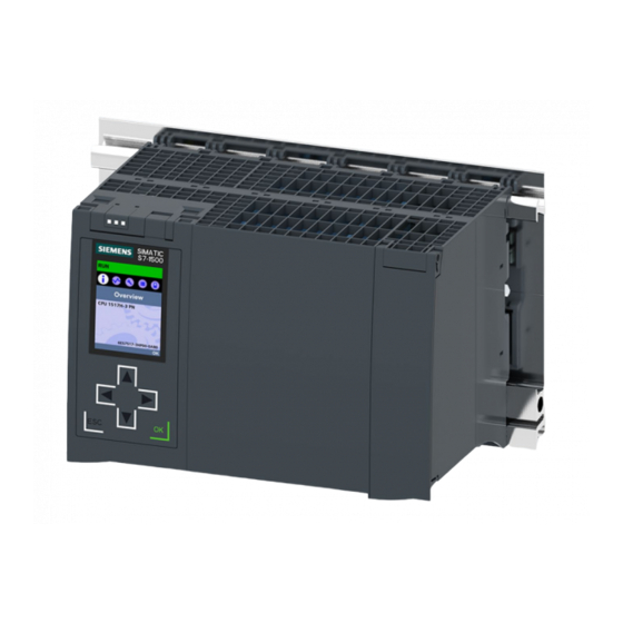
Product overview 2.3 Hardware properties Hardware properties Article number 6ES7517-3HP00-0AB0 View of the module The figure below shows the CPU 1517H-3 PN. Figure 2-2 CPU 1517H-3 PN Note Protective film Note that there is a removable protective foil on the display when the CPUs are delivered. CPU 1517H-3 PN (6ES7517-3HP00-0AB0) Equipment Manual, 11/2019, A5E42011886-AB... - Page 16 All CPUs of the redundant system S7 1500R/H have a Redundant System S7-1500R/H • display with plain text information. The display provides (https://support.industry.siemens. you with diagnostic messages as well as information com/cs/ww/en/view/109754833) about the article number, the firmware version and the System Manual serial number of the CPU.
- Page 17 The CPU has an X1 interface with two ports (X1 P1 R Redundant System S7-1500R/H • (X1 P1 R and X1 P2 R) and X1 P2 R). (https://support.industry.siemens. com/cs/ww/en/view/109754833) The PROFINET IO interface X1 (default P1 R) is • System Manual used to set up the PROFINET ring with the two CPUs and the IO devices.
-
Page 18: Firmware Functions
There are two duplicate CPUs that synchronize their Redundant System S7-1500R/H data via two duplex fiber-optic cables, which connect (https://support.industry.siemens.co the CPUs directly to each other via plug-in synchroniza- m/cs/ww/en/view/109754833) Sys- tion modules. If one of the CPUs fails, the other CPU tem Manual retains control of the process. - Page 19 Additional information RT (real time) RT prioritizes PROFINET IO frames over standard Function manual PROFINET frames. This ensures the required determinism in the (http://support.automation.siemens.c automation technology. In this process the data is om/WW/view/en/49948856) transferred via prioritized Ethernet frames. MRP (Media Redundancy...
-
Page 20: Operator Controls And Display Elements
Product overview 2.5 Operator controls and display elements Operator controls and display elements 2.5.1 Front view of the CPU with closed front flap The figure below shows the front view of the CPU 1517H-3 PN. ① LEDs for the current operating state and diagnostic status of the CPU ②... - Page 21 (local lock) and assign a password for the display. You can find additional information on the display, the configurable protection levels and the local lock in the system manual for Redundant System S7-1500R/H (https://support.industry.siemens.com/cs/ww/en/view/109754833). Reference You can find detailed information on the individual display options, a training course and a simulation of the available menu commands in the SIMATIC S7-1500 Display Simulator (http://www.automation.siemens.com/salesmaterial-as/interactive-manuals/getting-...
-
Page 22: Front View Of The Cpu Without Front Flaps
Product overview 2.5 Operator controls and display elements 2.5.2 Front view of the CPU without front flaps The figure below shows the operator controls and connection elements of the CPU 1517H-3 PN. ① Mode selector ② No function ③ LED displays for the ports of the X3 and X4 interfaces ④... -
Page 23: Rear View Of The Cpu
Product overview 2.5 Operator controls and display elements 2.5.3 Rear view of the CPU The figure below shows the connection elements on the rear of the CPU 1517H-3 PN. ① Shield contact surfaces ② Plug-in connection for power supply ④ Fixing screws Figure 2-6 View of the CPU 1517H-3 PN - rear... -
Page 24: Bottom View
Product overview 2.5 Operator controls and display elements 2.5.4 Bottom view Interfaces and synchronization modules The figure below shows the position of the interfaces on the underside of the CPU. ① PROFINET IO interface X1 with 2 ports ② PROFINET IO interface X2 with 1 port ③... -
Page 25: Mode Selector
You can find a brief overview of the various operating states and system states in the section Status and error display of the CPU (Page 29). You can find a detailed description of the operating states and system states in the system manual for S7-1500R/H Redundant System (https://support.industry.siemens.com/cs/ww/en/view/109754833). CPU 1517H-3 PN (6ES7517-3HP00-0AB0) Equipment Manual, 11/2019, A5E42011886-AB... -
Page 26: Connecting
1L+ and 2L+ as well as 1M and 2M are bridged internally Maximum 10 A permitted You can find information on the various supply options in the system manual for Redundant System S7-1500R/H (https://support.industry.siemens.com/cs/ww/en/view/109754833). CPU 1517H-3 PN (6ES7517-3HP00-0AB0) Equipment Manual, 11/2019, A5E42011886-AB... - Page 27 Connecting 3.1 Terminal assignment PROFINET interface X1 with 2-port switch (X1 P1 R and X1 P2 R) The assignment corresponds to the Ethernet standard for an RJ45 plug. ● When autonegotiation is deactivated, the RJ45 socket is allocated as a switch (MDI-X). ●...
- Page 28 Additional information You can find additional information on the topic of "Connecting the CPU" and on the topic "Accessories/spare parts" in the system manual for Redundant System S7-1500R/H (https://support.industry.siemens.com/cs/ww/en/view/109754833). Assignment of the MAC addresses For each CPU, CPU 1517H-3 PN has: ●...
- Page 29 Connecting 3.1 Terminal assignment Block diagram The following figure shows the block diagram of the CPU 1517H-3 PN. ① SIMATIC memory card (X50) PN X1 P2 R PROFINET interface X1 port 2 ② Display PN X2 P1 PROFINET interface X2 port 1 ③...
-
Page 30: Interrupts, Diagnostics, Error Messages And System Events
You can find more detailed information on "Interrupts" in the STEP 7 online help. You can find additional information on the topic of "Diagnostics" and "System events" in the Diagnostics (http://support.automation.siemens.com/WW/view/en/59192926) function manual and in the system manual Redundant System S7-1500R/H (https://support.industry.siemens.com/cs/ww/en/view/109754833). - Page 31 Interrupts, diagnostics, error messages and system events 4.1 Status and error display of the CPU LED displays depending on operating states and system states CPU 1517H-3 PN has the following LEDs for displaying the current operating state and diagnostics status. ●...
- Page 32 Interrupts, diagnostics, error messages and system events 4.1 Status and error display of the CPU Meaning of the RUN/STOP, ERROR and MAINT LEDs CPU 1517H-3 PN has the following LEDs for displaying the current operating state and diagnostics status. Note LED patterns of the S7-1500H redundant system Note that it is not always possible to: •...
- Page 33 Interrupts, diagnostics, error messages and system events 4.1 Status and error display of the CPU The following table shows the meaning of the various color combinations for the RUN/STOP, ERROR and MAINT LEDs. Table 4- 1 Meaning of the LEDs RUN/STOP LED ERROR LED MAINT LED...
- Page 34 Interrupts, diagnostics, error messages and system events 4.1 Status and error display of the CPU Note MAINT LED of the two CPUs The MAINT LEDs of both CPUs only go out when the following conditions are fulfilled: • The CPUs are in the RUN-Redundant system state. •...
- Page 35 Interrupts, diagnostics, error messages and system events 4.1 Status and error display of the CPU Note "LED" instruction You can read the status (e.g. "On" or "Off") of LEDs of a CPU or a module using the "LED" instruction. Note, however, that it is not possible to read the LED status of the LINK RX/TX LEDs on all S7-1500 R/H CPUs.
-
Page 36: Technical Specifications
Technical specifications The following table shows the technical specifications as of 11/2019. You can find a data sheet including daily updated technical specifications on the Internet (https://support.industry.siemens.com/cs/ww/en/pv/6ES7517-3HP00-0AB0/td?dl=en). Article number 6ES7517-3HP00-0AB0 General information Product type designation CPU 1517H-3 PN HW functional status... - Page 37 Technical specifications Article number 6ES7517-3HP00-0AB0 Work memory 2 Mbyte integrated (for program) • 8 Mbyte integrated (for data) • Load memory 32 Gbyte Plug-in (SIMATIC Memory Card), max. • Backup maintenance-free • CPU processing times for bit operations, typ. 4 ns for word operations, typ.
- Page 38 Technical specifications Article number 6ES7517-3HP00-0AB0 Counters, timers and their retentivity S7 counter 2 048 Number • Retentivity – adjustable IEC counter Any (only limited by the main memory) Number • Retentivity – adjustable S7 times 2 048 Number • Retentivity –...
- Page 39 Technical specifications Article number 6ES7517-3HP00-0AB0 Hardware configuration Number of distributed IO systems Number of IO Controllers integrated • Time of day Clock Hardware clock Type • 6 wk; At 40 °C ambient temperature, typically Backup time • 10 s; Typ.: 2 s Deviation per day, max.
- Page 40 Technical specifications Article number 6ES7517-3HP00-0AB0 PROFINET IO Controller Services – PG/OP communication – S7 routing – Isochronous mode – Open IE communication – Yes; Only Manager Auto, max. 50 nodes – – MRPD – PROFIenergy – Number of connectable IO Devices, max.
- Page 41 Technical specifications Article number 6ES7517-3HP00-0AB0 Interface types RJ 45 (Ethernet) 100 Mbps • Autonegotiation • Autocrossing • Industrial Ethernet status LED • Protocols Number of connections Number of connections, max. • Number of connections reserved for • ES/HMI/web Number of S7 routing paths •...
- Page 42 Technical specifications Article number 6ES7517-3HP00-0AB0 OPC UA OPC UA client • OPC UA server • Further protocols Yes; MODBUS TCP MODBUS • Media redundancy 200 ms; PROFINET MRP Switchover time on line break, typ. • Number of stations in the ring, max. •...
- Page 43 Technical specifications Article number 6ES7517-3HP00-0AB0 Diagnostic buffer present • 3 200 Number of entries, max. • 1 000 – of which powerfail-proof Traces Number of configurable Traces • 512 kbyte Memory size per trace, max. • Interrupts/diagnostics/status information Diagnostics indication LED RUN/STOP LED •...
- Page 44 2 119 g; Interface modules: 2x 18 g General technical specifications You can find information on the general technical specifications, such as standards and approvals, electromagnetic compatibility, protection class, etc. in the system manual for Redundant System S7-1500R/H (https://support.industry.siemens.com/cs/ww/en/view/109754833). CPU 1517H-3 PN (6ES7517-3HP00-0AB0) Equipment Manual, 11/2019, A5E42011886-AB...
-
Page 45: A Dimension Drawing
Dimension drawing Dimension drawing This section contains the dimension drawing of the module on the mounting rail, as well as a dimension drawing with the front panel open. Keep to the dimensions when installing in cabinets, control rooms, etc. Dimension drawings of the CPU 1517H-3 PN Figure A-1 Dimension drawing of the CPU 1517H-3 PN, front and side view CPU 1517H-3 PN (6ES7517-3HP00-0AB0) - Page 46 Dimension drawing A.1 Dimension drawing Figure A-2 Dimension drawing of the CPU 1517H-3 PN, side view with front panel open CPU 1517H-3 PN (6ES7517-3HP00-0AB0) Equipment Manual, 11/2019, A5E42011886-AB...