Table of Contents
SERVICE MANUAL
Ver. 1.1 2015.06
Amplifi er section
The following are measured at
AC 120 V – 240 V, 50/60 Hz
Power output (rated)
Left/Right Channel: 400 W + 400 W
(per channel at 4 ohms, 1 kHz, 1% THD)
RMS output power (reference)
Left/Right Channel: 720 W + 720 W
(per channel at 4 ohms, 1 kHz)
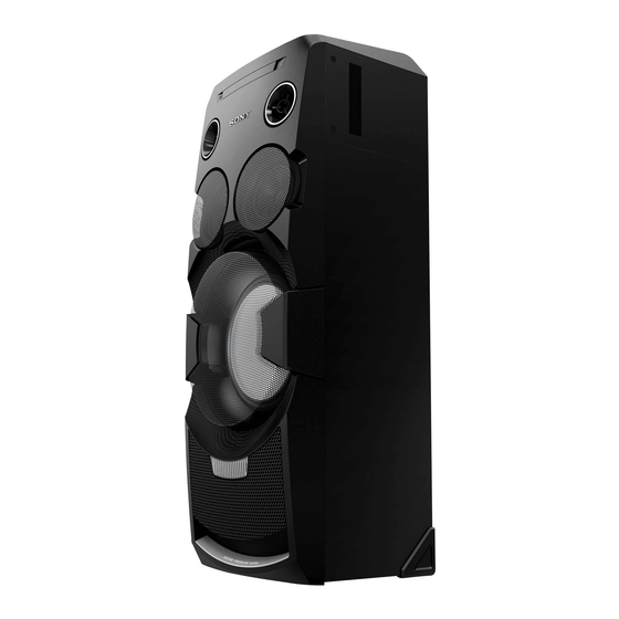
Speaker section
Speaker system:
Tweeter + Mid range speaker + Woofer
Tweeter L/R: 40 mm cone type
Mid L/R: 120 mm cone type
Woofer: 250 mm cone type
Inputs
AUDIO IN 1/PARTY CHAIN IN L/R
Voltage 2 V, impedance 47 kilohms
AUDIO IN 2 L/R
Voltage 2 V, impedance 47 kilohms
MIC 1, MIC 2
Sensitivity 1 mV, impedance 10 kilohms
(USB) 1,
(USB) 2 port:
Type A
Outputs
AUDIO OUT/PARTY CHAIN OUT L/R
Voltage 2 V, impedance 1 kilohm
VIDEO OUT
Max. output level 1 Vp-p, unbalanced,
Sync. negative load impedance 75 ohms
USB section
Supported bit rate
WMA: 48 kbps – 192 kbps, VBR, CBR
AAC: 48 kbps – 320 kbps, VBR, CBR
Sampling frequencies
WMA: 44.1 kHz
AAC: 44.1 kHz
Supported USB device
Mass Storage Class
Maximum current
1 A
9-890-671-02
Sony Corporation
2015F80-1
©
2015.06
Published by Sony EMCS (Malaysia) PG Tec
Model Name Using Similar Mechanism
DVD
DVD Mechanism Type
Section
Optical Pick-up Name
SPECIFICATIONS
Disc/USB section
Supported bit rate
MPEG1 Layer-3:
32 kbps – 320 kbps, VBR
Sampling frequencies
MPEG1 Layer-3:
32 kHz/44.1 kHz/48 kHz
Xvid
Video codec: Xvid
Bit rate: 4.854 Mbps (MAX)
Resolution/Frame rate:
720 × 480, 30 fps
720 × 576, 25 fps
Audio codec: MP3
MPEG4
File format: MP4 File Format
Video codec:
MPEG4 Simple Profi le
(AVC is not compatible.)
Bit rate: 4 Mbps
Resolution/Frame rate:
720 × 576, 30 fps
Audio codec: AAC-LC
(HE-AAC is not compatible.)
DRM: Not compatible
Disc player section
System
Compact disc and digital audio and
video system
Laser Diode Properties
Emission Duration: Continuous
Laser Output*: Less than 44.6 μW
* This output is the value measure-
ment at a distance of 200 mm from
the objective lens surface on the
Optical Pick-up Block with 7 mm
aperture.
Frequency response
20 Hz – 20 kHz
Video color system format
NTSC and PAL
MHC-V7D
HCD-GPX555/GPX888
CDM90-DVBU204//C
CMS-S76RFS7G1 OR CMS-S76RFS7GP
Tuner section
FM stereo, FM superheterodyne tuner
Antenna
FM lead antenna
Tuning range
87.5 MHz – 108.0 MHz (50 kHz step)
BLUETOOTH section
Communication system
BLUETOOTH Standard version 3.0
Output
BLUETOOTH Standard Power Class 2
Maximum communication range
Line of sight approx. 10 m
1)
Frequency band
2.4 GHz band (2.4000 GHz –
2.4835 GHz)
Modulation method
FHSS (Freq Hopping Spread Spectrum)
Compatible BLUETOOTH profiles
2)
A2DP (Advanced Audio Distribution
Profile)
AVRCP (Audio Video Remote
Control Profile)
SPP (Serial Port Profile)
Supported codecs
SBC (Sub Band Codec)
AAC (Advanced Audio Coding)
The actual range will vary depending on
1)
factors such as obstacles between devices,
magnetic fields around a microwave oven,
static electricity, reception sensitivity,
antenna's performance, operating system,
software application, etc.
BLUETOOTH standard profiles
2)
indicate the purpose of BLUETOOTH
communication between devices.
HOME AUDIO SYSTEM
AEP Model
UK Model
E Model
Australian Model
General
Power requirements
AC 120 V – 240 V, 50/60 Hz
Power consumption
220 W
Power consumption (at the Power Saving
mode)
0.5 W (When "BT STBY" is set to
"OFF")
4 W (When "BT STBY" is set to
"ON")
Dimensions (w/h/d) (Approx.)
340 mm × 924 mm × 320 mm
Mass (Approx.)
19 kg
Supplied accessories
• Remote control (1)
• R03 (size AAA) batteries (2)
• FM lead antenna (1)
• AC power cord (mains lead) (1)
• AC plug adaptor (1) (supplied only for
certain areas)
The AC plug adaptor is not use in Chile. Use
this plug adaptor in the countries where it is
necessary.
Design and specifications are subject to
change without notice.
– Continued on next page –
Table of Contents

Related Manuals for Sony MHC-V7D


Summary of Contents for Sony MHC-V7D
- Page 1 20 Hz – 20 kHz Supported USB device Video color system format Mass Storage Class – Continued on next page – NTSC and PAL Maximum current HOME AUDIO SYSTEM 9-890-671-02 Sony Corporation 2015F80-1 © 2015.06 Published by Sony EMCS (Malaysia) PG Tec...
- Page 2 Bluetooth SIG, Inc. and any use of such marks by Sony 2. A battery-operated AC milliammeter. The Data Precision 245 Corporation is under license. Other trademarks and trade names are those of their respective owners.
-
Page 3: Table Of Contents
MHC-V7D Ver. 1.1 TABLE OF CONTENTS SERVICING NOTES ..........6-15. Printed Wiring Board - 2CH DAMP Board - ....48 6-16. Schematic Diagram - 2CH DAMP Board - ....49 DISASSEMBLY 6-17. Printed Wiring Board - STR Board - ......50 2-1. -
Page 4: Servicing Notes
MHC-V7D Ver. 1.1 SECTION 1 SERVICING NOTES Notes on chip component replacement MODEL IDENTIFICATION • Never reuse a disconnected chip component. – Back Panel – • Notice that the minus side of a tantalum capacitor may be damaged by heat. - Page 5 6. Select the model number of the unit on the display of the Bluetooth device. For example, select “SONY : MHC-V7D”. If passkey is required on the Bluetooth device, enter “0000”. 7. Perform the Bluetooth connection on the Bluetooth device.
- Page 6 MHC-V7D BOND FIXATION OF ELECTRIC PARTS Playing music from a Bluetooth device When 2CH DAMP board is replaced or the following object parts are replaced, it is necessary to fi x parts to the boards by using a For a Bluetooth device specifi...
- Page 7 MHC-V7D Ver. 1.1 HOW TO OPEN THE TRAY WHEN POWER SWITCH TURN OFF Note 1: After the side case and top panel block are removed, this work is done. Note 2: Please prepare the thin wire (clip etc. processed to the length of 8 cm or more).
- Page 8 MHC-V7D CAPACITOR DISCHARGE FOR ELECTRIC SHOCK PREVENTION Switching Regulator Board (Conductor side view) In checking the Switching Regulator board, make 3 capacitors discharge of C18, C20 and C27 for eletrical shock prevention. 800 /5 W 800 /5 W 800 /5 W...
-
Page 9: Disassembly
MHC-V7D Ver. 1.1 SECTION 2 DISASSEMBLY Note: Disassemble the unit in the order as shown below. 2-1. DISASSEMBLY FLOW 2-2. SIDE CASE L, R (Page 10) 2-3. TOP PANEL BLOCK (Page 10) 2-4. PANEL LOADING BLOCK (Page 11) 2-5. BACK PANEL BLOCK (Page 12) 2-6. -
Page 10: Side Case L, R
MHC-V7D Ver. 1.1 Note: Follow the disassembly procedure in the numerical order given. 2-2. SIDE CASE L, R 4 side case L 2 two screws (+BVTP 3 1 two screws (tapping (HEX)) 2 two screws (+BVTP 3 3 Remove the side case L in the direction of the arrow. -
Page 11: Panel Loading Block
MHC-V7D Ver. 1.1 2-4. PANEL LOADING BLOCK 3 three claws 4 panel loading block hole – Left view – 2 Draw out the tray. Insert the clip etc. processed to the length of 8 cm or more in the hole 1 Insert the clip etc. -
Page 12: Back Panel Block
MHC-V7D Ver. 1.1 2-5. BACK PANEL BLOCK 1 CN1011 (2P) hole hook 2 two screws (+BVTP 3 2 three screws (+BVTP 3 2 three screws (+BVTP 3 – Top rear view – 2 three screws 3 panel, back block (+BVTP 3 Note 2: When you install the connector, please install them correctly. -
Page 13: Cdm Block
MHC-V7D Ver. 1.1 2-6. CDM BLOCK 9 CDM block 4 two screws 7 Release the catchers before (+BVTP 3 remove the CDM block. 5 clamp (AEP, UK, RU, AUS) 8 Remove the CDM block in the direction of the arrow. -
Page 14: Motherboard Board, 2Ch Damp Board
MHC-V7D Ver. 1.1 2-7. MOTHERBOARD BOARD, 2CH DAMP BOARD qg three screws (+PTPWH 2.6 L (DIA8.0)) • Abbreviation : Australian model qh heat sink : Russian model qd one screw (+BVTP 3 qk sheet, qf clamp thermal qd one screw... -
Page 15: Regulator, Switching (Ssn-152Ad)
MHC-V7D Ver. 1.1 2-8. REGULATOR, SWITCHING (SSN-152AD) 2 Remove the wire from the hole. 3 two screws (+BVTP 3 6 chassis, sub 4 one screw (+BVTP 3 5 clamp 4 one screw 3 two screws (+BVTP 3 (+BVTP 3 5 clamp... -
Page 16: Front Panel Block
MHC-V7D Ver. 1.1 2-9. FRONT PANEL BLOCK 2 Insert the jig into a space and slowly remove the panel, front block. Note 1: When using a jig, please work 1 one tapping screw so as not to injure panel, front (1) (3.5 x 14) -
Page 17: Loudspeaker (25Cm) (Woofer) (Sp5)
MHC-V7D 2-10. LOUDSPEAKER (25cm) (WOOFER) (SP5) 3 terminal loudspeaker (25cm) (wide side) [grey] terminal position (SP5) 3 terminal (narrow) [black] 1 eight screws 16) (TYPE1), +BVTP) 2 Remove the loudspeaker (25cm) (SP5) 4 loudspeaker (25cm) in the direction of the arrow. -
Page 18: Loudspeaker (12Cm) (Mid: L-Ch) (Sp1), Loudspeaker (12Cm) (Mid: R-Ch) (Sp3)
MHC-V7D Ver. 1.1 2-11. LOUDSPEAKER (12cm) (MID: L-CH) (SP1), LOUDSPEAKER (12cm) (MID: R-CH) (SP3) terminal position 1 cushion (E 0.5) loudspeaker loudspeaker (12cm) (SP1) (12cm) (SP3) 2 core, ferrite 5 terminal (wide side) 5 terminal (narrow side) 4 Remove the loudspeaker (12cm) (SP1) in the direction of the arrow. -
Page 19: Service, Optical Device (7G), Flexible Flat Cable
MHC-V7D Ver. 1.1 2-12. SERVICE, OPTICAL DEVICE (7G), FLEXIBLE FLAT CABLE 2 chuck holder assy (MB) 1 six claws qa insulator qf flexible flat cable (5P) 8 four insulator screws qs service, qh cushion (H) optical device (7G) qa insulator... -
Page 20: Test Mode
2. Press [] button and [TUNING + >] button simultaneously for 3 seconds. 3. “COLD RST” appears on the fl uorescent indicator tube. After that, the fluorescent indicator tube will display “SONY”. The set will automatically Power ON and Power OFF again, and the system is reset. - Page 21 MHC-V7D [HISTORY MODE] This mode is used to check important data stored in the system when PROTECTOR happen. Procedure: 1. During demo mode, press [] button and [+] button for 5 seconds to mode into history mode. 2. Press the [TUNING + >] button or [TUNING ‒ .] button to check history data stored.
- Page 22 Menu” change with the model and the destination appears on 3. Focus Balance Adjust: 4. Focus Gain Adjust: screen display. Refer to below on the model name. 5. Eq Boost Adjust: MHC-V7D: KIRIN 6. Iop. ED 7. TRV. Level: Remocon Diagnosis Menu 8. S curve (FE) Level: 9.
- Page 23 MHC-V7D 9. Press the [RETURN] button on the remote commander to • Parameter of error code return to previous menu. This is the detail of error code. 10. Press the [0] button on the remote commander to return to the Top Menu of Remocon Diagnosis Menu.
- Page 24 MHC-V7D To return to the Top Menu of Remocon Diagnosis Menu Press the [0] button on the remote commander. • Check Version Information To check the version information, please follow the following procedure. 1. From the Top Menu of Remocon Diagnosis Menu, select “4.
-
Page 25: Electrical Check
MHC-V7D SECTION 4 ELECTRICAL CHECK TUNER SECTION 0 dB = 1 V FM AUTO STOP CHECK signal generator – Procedure: 1. Turn the power on. 2. Input the following signal from Signal Generator to FM antenna input directly. Carrier frequency : A = 87.5 MHz, B = 98 MHz, C = 108 MHz... - Page 26 MHC-V7D Checking Location: CD/DVD SECTION -MOTHERBOARD Board (COMPONENT SIDE)- [TEST DISC LIST] Use the following test disc on test mode. • CD: YEDS-18 (PART No. 3-702-101-01) PATD-012 (PART No. 4-225-203-01) HLX-A1 (PART No. J-2501-307-A) • DVD (SL) NTSC HLX-503 (PART No. J-6090-069-A) HLX-504 (PART No.
-
Page 27: Troubleshooting
MHC-V7D SECTION 5 TROUBLESHOOTING... - Page 28 MHC-V7D...
- Page 29 MHC-V7D...
- Page 30 MHC-V7D...
- Page 31 MHC-V7D...
- Page 32 MHC-V7D Ver. 1.1...
-
Page 33: Diagrams
MHC-V7D SECTION 6 DIAGRAMS 6-1. BLOCK DIAGRAM - RS SERVO, USB Section - CD RF AMP FOCUS/TRACKING ERROR AMP CD SYSTEM PROCESSOR DIGITAL SERVO PROCESSOR IC301 (1/2) RFIP VOA/A RF_C VOB/B RF_B VOC/C RF_A VOD/D RF_D XTALO 8 VOE/E+G RF_F... -
Page 34: Block Diagram - Main Section
MHC-V7D 6-2. BLOCK DIAGRAM - MAIN Section - PARTY AUDIO CHAIN OUT J601 (2/2) SIGNAL SELECTOR OP AMP ANALOG IC602 IC601 SELECTOR MIC AMP CONVERTER Q605, Q607 IC3500 IC609 OUT 1 J3501 X 13 OUT 7 VINL BCK 8 MIC 2... -
Page 35: Block Diagram - Amp Section
MHC-V7D 6-3. BLOCK DIAGRAM - AMP Section - POWER AMP +63V IC1008 SPB1 SPK BOX ASSY DIGITAL AUDIO MOSFET CN1005 Q1000 CSL1 OP AMP IC1009 DIGITAL AUDIO MOSFET >001B Q1001 DC DETECT FRONT-L 7 VINL1 VOUTL1 2 IN-2 MAIN SECTION... -
Page 36: Block Diagram - Panel, Power Supply Section
MHC-V7D 6-4. BLOCK DIAGRAM - PANEL, POWER SUPPLY Section - LIQUID CRYSTAL DISPLAY LIQUID CRYSTAL DISPLAY DRIVER ND3200 IC3204 SPM-C-MON PROTECTION CONTROL PCONT-DAMP 38 LCD-CSB / TEST-MON38 Q576 VOLTAGE REGULATOR 35 LCD-CLK / FL-CLK IC002 POWER CONTROL 40 LCD-SDA / FL-SOUT... - Page 37 MHC-V7D Ver. 1.1 • Note for Printed Wiring Boards and Schematic Diagrams • Circuit Boards Location LCD board PARTY LED board Note on Printed Wiring Board: Note on Schematic Diagram: • X : parts extracted from the component side. • All capacitors are in μF unless otherwise noted. (p: pF) STR board •...
-
Page 38: Printed Wiring Board - Motherboard Board (Component Side)
MHC-V7D 6-5. PRINTED WIRING BOARD - MOTHERBOARD Board (Component Side) - • See page 37 for Circuit Boards Location. • : Uses unleaded solder. MOTHERBOARD BOARD (COMPONENT SIDE) J601 SPK LED BOARD (LEFT) AUDIO AUDIO IN 2 IN 2 CN3900... -
Page 39: Printed Wiring Board - Motherboard Board (Conductor Side)
MHC-V7D 6-6. PRINTED WIRING BOARD - MOTHERBOARD Board (Conductor Side) - • See page 37 for Circuit Boards Location. • : Uses unleaded solder. MOTHERBOARD BOARD (CONDUCTOR SIDE) Q602, Q603, Q605, Q607 JL907 B2 E2 Z502 B1 C2 R543 IC502... -
Page 40: Schematic Diagram - Motherboard Board (1/8)
MHC-V7D 6-7. SCHEMATIC DIAGRAM - MOTHERBOARD Board (1/8) - • See page 62 for IC Block Diagrams. >003S AUDIO IN 2 MOTHERBOARD BOARD (1/8) MOTHERBOARD BOARD (7/8) (Page 46) R756 6.8k J907 R624 2.2k PARTY CHAIN IN AUDIO IN 1... -
Page 41: Schematic Diagram - Motherboard Board (2/8)
MHC-V7D Ver. 1.1 6-8. SCHEMATIC DIAGRAM - MOTHERBOARD Board (2/8) - • See page 62 for IC Block Diagrams. MOTHERBOARD BOARD (2/8) L605 2.2nH 3.3 5.5 C938 C933 C934 C935 C937 R938 0.0022u C941 IC903 MM3411A33URE R859 C943 X600 IC903 12MHz +3.3V REG. -
Page 42: Schematic Diagram - Motherboard Board (3/8)
MHC-V7D 6-9. SCHEMATIC DIAGRAM - MOTHERBOARD Board (3/8) - • See page 61 for Waveforms. • See page 62 for IC Block Diagrams. • See page 68 for IC Pin Function Descriptions. >029S >011S MOTHERBOARD >022S MOTHERBOARD BOARD (1/8) BOARD (4/8) -
Page 43: Schematic Diagram - Motherboard Board (4/8)
MHC-V7D 6-10. SCHEMATIC DIAGRAM - MOTHERBOARD Board (4/8) - • See page 62 for IC Block Diagrams. MOTHERBOARD BOARD (4/8) CL412 R433 CL413 FE_3.3V_1 CL415 >031S CL414 Q401 Q402 MOTHERBOARD 2SA2119K 2SA2119K C420 AUTO POWER AUTO POWER C423 R422 R431... -
Page 44: Schematic Diagram - Motherboard Board (5/8)
MHC-V7D 6-11. SCHEMATIC DIAGRAM - MOTHERBOARD Board (5/8) - • See page 61 for Waveforms. • See page 62 for IC Block Diagrams. MOTHERBOARD BOARD (5/8) D+3.3V USB_DM0 >040S C454 C456 C457 USB_HOST_SEL 0.1u MOTHERBOARD BOARD R480 (8/8) NC_14 X451... -
Page 45: Schematic Diagram - Motherboard Board (6/8)
MHC-V7D 6-12. SCHEMATIC DIAGRAM - MOTHERBOARD Board (6/8) - • See page 61 for Waveforms. >045S >017S >012S >046S MOTHERBOARD BOARD (7/8) >047S MOTHERBOARD BOARD MOTHERBOARD (Page 46) MOTHERBOARD (2/8) BOARD MOTHERBOARD BOARD BOARD (Page 41) (2/8) (7/8) (7/8) (Page 46) -
Page 46: Schematic Diagram - Motherboard Board (7/8)
MHC-V7D 6-13. SCHEMATIC DIAGRAM - MOTHERBOARD Board (7/8) - • See page 62 for IC Block Diagrams. >045S >018S >042S MOTHERBOARD >019S >002S MOTHERBOARD BOARD (2/8) >036S >003S >005S BOARD MOTHERBOARD (Page 41) MOTHERBOARD MOTHERBOARD (6/8) MOTHERBOARD MOTHERBOARD BOARD MOTHERBOARD... -
Page 47: Schematic Diagram - Motherboard Board (8/8)
MHC-V7D 6-14. SCHEMATIC DIAGRAM - MOTHERBOARD Board (8/8) - • See page 61 for Waveforms. • See page 62 for IC Block Diagrams. • See page 68 for IC Pin Function Descriptions. MOTHERBOARD >043S BOARD R113 EVER+3.3V MOTHERBOARD R198 E+3.3V... -
Page 48: Printed Wiring Board - 2Ch Damp Board
MHC-V7D Ver. 1.1 6-15. PRINTED WIRING BOARD - 2CH DAMP Board - • See page 37 for Circuit Boards Location. • : Uses unleaded solder. 2CH DAMP BOARD 2CH DAMP BOARD (COMPONENT SIDE) (CONDUCTOR SIDE) Q1002, Q1003, Q1016, Q1018, Q1019, Q1021... -
Page 49: Schematic Diagram - 2Ch Damp Board
MHC-V7D Ver. 1.1 6-16. SCHEMATIC DIAGRAM - 2CH DAMP Board - • See page 62 for IC Block Diagrams. 2CH DAMP BOARD IC1006 78D07AG-TN3-R IC1006 +7V REG. R1282 CL1062 23.9 C1166 C1157 C1155 0.1u 0.47u R1222 R1147 C1165 C1158 C1156 0.1u... -
Page 50: Printed Wiring Board - Str Board
MHC-V7D 6-17. PRINTED WIRING BOARD - STR Board - • See page 37 for Circuit Boards Location. • : Uses unleaded solder. MOTHERBOARD REC/PLAY PLAY STR BOARD BOARD CN451 (Page 38) >005P JR3460 S3001 S3002 LP3001 C3027 C3019 SOUND FIELD... -
Page 51: Schematic Diagram - Str Board
MHC-V7D Ver. 1.1 6-18. SCHEMATIC DIAGRAM - STR Board - • See page 62 for IC Block Diagrams. STR BOARD S3013 TUNING – CL3099 R3037 S3014 – CL3100 R3036 S3020 C3032 2.2u 50V VOCAL FADER CL3097 CL3108 NO3000 R3050 RV3001 >055S... -
Page 52: Printed Wiring Board - Gesture Board
MHC-V7D 6-19. PRINTED WIRING BOARD - GESTURE Board - • See page 37 for Circuit Boards Location. • : Uses unleaded solder. GESTURE BOARD GESTURE BOARD (COMPONENT SIDE) (CONDUCTOR SIDE) CL3636 GESTURE CONTROLLER PLAYBACK D003 R3617 D002 D006 D005 R3616... -
Page 53: Schematic Diagram - Gesture Board
MHC-V7D Ver. 1.1 6-20. SCHEMATIC DIAGRAM - GESTURE Board - • See page 62 for IC Block Diagrams. GESTURE BOARD D004 BAV99-215 D003 BAV99-215 D002 BAV99-215 R3612 R3608 D001 R3613 BAV99-215 R3615 R3617 R3618 R3611 R3616 C3604 100p CN3600 CL3628... -
Page 54: Printed Wiring Board - Gesture Led Board
MHC-V7D 6-21. PRINTED WIRING BOARD - GESTURE LED Board - 6-22. SCHEMATIC DIAGRAM - GESTURE LED Board - • • See page 62 for IC Block Diagrams. • See page 37 for Circuit Boards Location. : Uses unleaded solder. GESTURE LED BOARD... -
Page 55: Printed Wiring Board - Lcd Board
MHC-V7D 6-23. PRINTED WIRING BOARD - LCD Board - • • See page 37 for Circuit Boards Location. : Uses unleaded solder. LCD BOARD ND3200 LIQUID CRYSTAL DISPLAY CL3244 JR3221 CL3241 CL3240 JR3220 CL3243 JR3223 CL3203 D3200 CL3275 IC3204 Q3200... -
Page 56: Schematic Diagram - Lcd Board
MHC-V7D 6-24. SCHEMATIC DIAGRAM - LCD Board - • See page 62 for IC Block Diagrams. LCD BOARD ND3200 LIQUID CRYSTAL DISPLAY SEG24 SEG_12 SEG12 SEG24 SEG25 SEG11 SEG25 SEG11 SEG26 SEG10 SEG26 SEG10 SEG27 SEG9 SEG27 SEG9 SEG28 SEG8... -
Page 57: Printed Wiring Board - Mic Board
MHC-V7D 6-25. PRINTED WIRING BOARD - MIC Board - • See page 37 for Circuit Boards Location. • : Uses unleaded solder. J3501 J3500 MIC BOARD CL3525 C3525 C3526 CL3514 CL3516 CL3519 R3510 CL3510 R3502 CL3512 CL3523 CL3513 C3522 C3516... -
Page 58: Schematic Diagram - Mic Board
MHC-V7D 6-26. SCHEMATIC DIAGRAM - MIC Board - MIC BOARD >006S CN3500 FB3502 MOTHERBOARD CL3521 A+9V CL3522 BOARD MIC GND CL3523 MIC SIGNAL (1/8) CL3524 MIC DETECT CN601 (Page 40) CL3510 C3502 C3511 C3500 R3500 Q3500 2.2u 50V 2.2u R3518... -
Page 59: Printed Wiring Board - Party Led Board
MHC-V7D 6-29. PRINTED WIRING BOARD - PARTY LED Board - 6-31. PRINTED WIRING BOARD - SPK PARTY LED Board - • • • See page 37 for Circuit Boards Location. : Uses unleaded solder. • See page 37 for Circuit Boards Location. -
Page 60: Printed Wiring Board - Spk Led Board
MHC-V7D 6-33. PRINTED WIRING BOARD - SPK LED Board - 6-34. SCHEMATIC DIAGRAM - SPK LED Board - • • See page 37 for Circuit Boards Location. : Uses unleaded solder. SPK LED BOARD SPK LED BOARD (COMPONENT SIDE) (CONDUCTOR SIDE) -
Page 61
MHC-V7D • Waveforms – MOTHERBOARD Board – IC002 2 (VBST1) IC101 wh (SSI3_LRCKO) IC101 os (AUDIO-X2) IC301
- Page 62 MHC-V7D • IC Block Diagrams IC1008 CXD90038ER (2CH DAMP BOARD) IC3400 TC62D723FNG (GESTURE LED BOARD) IC502 TC62D723FNG (MOTHERBOARD BOARD (2/8)) IC3001 TC62D723FNG (STR BOARD) COMP1 OCH1 IN-1 25 GND Error detection result CSL1 SIN 2 Output open/short detection circuit data register...
- Page 63 MHC-V7D IC103 BU4229F-TR (MOTHERBOARD BOARD (7/8)) Vout – Vref IC106 MX25L3235EM2I-10G (MOTHERBOARD BOARD (8/8)) IC302 MX25L3235EM2I-10G (MOTHERBOARD BOARD (3/8)) Address Generator Memory Array Page Buffer HOLD Data Register Y-Decoder SRAM Buffer Sense Amplifier Mode State Logic Machine Generator Clock Generator...
- Page 64 MHC-V7D IC401 AM5890S (MOTHERBOARD BOARD (4/8)) Vcc2 Voltage Detection MUTE Actuator Spindle Driver (6X) Driver (4X) Thermal Shut down Vcc2 Vcc2 Vcc1 Sled Actuator Driver (4X) Driver (6X) Pre-DRV TRAY DRIVER IC451 GL850G-OGY33 (MOTHERBOARD BOARD (5/8)) USPORT FRTIMER Transceiver x40, x10...
- Page 65 MHC-V7D IC453 TC7USB40FT (MOTHERBOARD BOARD (5/8)) IC602, IC605 SN74LV4052APWR (MOTHERBOARD BOARD (1/8)) 2-COM 1-COM IC604 PCM1754DBQR (MOTHERBOARD BOARD (1/8)) SYSTEM SYSTEM 16 SCK CLOCK CLOCK MANAGER AUDIO SERIAL DATA MUTE SERIAL CONTROL PORT PORT LRCK 13 DEMP DGND POWER 4x/8x OVERSAMPLING DIGITAL SUPPLY FILTER &...
- Page 66 MHC-V7D Ver. 1.1 IC606, IC609 PCM1808PWR (MOTHERBOARD BOARD (1/8)) LRCK Serial Interface DOUT Mode/ Format Control Clock SCKI Timing Control x1/64 Decimation Filter with High Pass Filter DGND Delta Sigma Delta Sigma Modulator Modulator Power Supply Antialias AGND VINL Reference...
- Page 67 MHC-V7D IC913 TC7WH157FK (MOTHERBOARD BOARD (2/8)) 11 7 11 6 SELECT EN G GND 4 IC914 PCM5101 (MOTHERBOARD BOARD (2/8)) Current Segment LRCK Current Segment Zero Data Detector VNEG Clock Halt Detection CPGND CAPP PLL Clock CPVDD Power UVP/Reset Supply...
- Page 68 MHC-V7D • IC Pin Function Descriptions MOTHERBOARD BOARD (8/8) IC101 R7S7200032CFP-A (SYSTEM CONTROL) Pin No. Pin Name Description SRC-RST0 Not used VIDEO-MUTE Muting Control for Video CDM-UNLOAD-SW CDM Open CDM-LOAD-SW CDM Close BT-RESET Reset signal output to Bluetooth section AC Supply Low Det AC Supply Low voltage Detection Power supply terminal (+3.3V)
- Page 69 MHC-V7D Pin No. Pin Name Description SSI1_DI Data In Signal from ADC to Aragon SD_FAST SD fast detect PCONT-PSAVE- Main power on/off control signal output “H”:power on PROTECT Power supply terminal (+3.3V) LINK-DET Party Chain input bias detection pin USB_HOST_SEL...
- Page 70 MHC-V7D Pin No. Pin Name Description TEST-MON108/ Test port for software checking. SD_CLK PVcc Power supply terminal (+3.3V) TEST-MON110/ Test port for software checking. SD_D0_0 3D_RESET/SD_D1_0 Motion sensor reset RGB-TRANS-LED- Transfer signal to RGB driver (driver for Speaker LED) SPK/SD_WP_0...
- Page 71 MHC-V7D Pin No. Pin Name Description USBUVss Ground terminal Ground terminal Ground terminal ANALOG-CSEL Multiplexer selector C for Analog input 3D_DETECT Motion sensor detection Q-Flash-SIO2 QSPI: Data I/O pins for channel 0 Q-Flash-SIO3 QSPI: Data I/O pins for channel 0...
- Page 72 MHC-V7D MOTHERBOARD BOARD (3/8) IC301 CXD9990R (CD RF AMP FOCUS/TRACKING ERROR AMP CD SYSTEM PROCESSOR DIGITAL SERVO PROCESSOR) Pin No. Pin Name Description RF_C RF main beam C input from the optical pick-up block RF_D RF main beam D input from the optical pick-up block...
- Page 73 MHC-V7D Pin No. Pin Name Description DQM0 Data mask signal output to the SD-RAM 62 to 69 RD15 to RD8 Two-way data bus with the SD-RAM DQM1 Data mask signal output to the SD-RAM DVDD33 Power supply terminal (+3.3V) (for digital system)
Page 74: Exploded Views
MHC-V7D Ver. 1.1 SECTION 7 EXPLODED VIEWS Note: • The mechanical parts with no reference • -XX and -X mean standardized parts, so The components identifi ed by mark 0 number in the exploded views are not sup- they may have some difference from the or dotted line with mark 0 are critical for plied.Page 75: Panel Loading Section
MHC-V7D Ver. 1.1 7-2. PANEL LOADING SECTION top panel section back panel section Ref. No. Part No. Description Remark 4-461-212-03 LOADING, BASE 4-569-030-01 SPRING (LP) 4-548-423-01 PANEL LOADING 7-685-646-71 SCREW +BVTP 3X8 TYPE2 IT-3...Page 76: Back Panel Section
MHC-V7D Ver. 1.1 7-3. BACK PANEL SECTION CDM block section not supplied MOTHERBOARD board section Ref. No. Part No. Description Remark 0 101 1-855-340-11 DC FAN 4-572-482-01 CUSHION 4-572-482-11 CUSHION 7-685-646-71 SCREW +BVTP 3X8 TYPE2 IT-3...Page 77: Motherboard Board Section
MHC-V7D Ver. 1.1 7-4. MOTHERBOARD BOARD SECTION not supplied not supplied not supplied supplied not supplied not supplied (AEP, UK, RU, AUS) supplied chassis section Note: If fl exible fl at cable is replaced, install it after bending it in the same form as that before replacement.Page 78: Chassis Section
MHC-V7D Ver. 1.1 7-5. CHASSIS SECTION not supplied not supplied (AEP, UK, RU, AUS) not supplied not supplied not supplied not supplied not supplied not supplied not supplied front panel section speaker cabinet section Ref. No. Part No. Description Remark Ref.Page 79: Front Panel Section
MHC-V7D Ver. 1.1 7-6. FRONT PANEL SECTION not supplied (DUMMY board) not supplied (IR board) supplied supplied supplied supplied not supplied (SPK LED board) supplied supplied not supplied (SPK LED board) not supplied not supplied (SPK PARTY LED board) not supplied Note: If fl...Page 80: Speaker Cabinet Section
MHC-V7D Ver. 1.1 7-7. SPEAKER CABINET SECTION (AEP, UK, RU, AUS) not supplied supplied supplied supplied not supplied Ref. No. Part No. Description Remark Ref. No. Part No. Description Remark 4-245-976-01 SCREW (4X16) (TYPE1), +BVTP 4-548-426-01 PROTECTOR CORNER L 4-874-614-12 SCREW (1) (3.5X14), TAPPING...Page 81: Top Panel Section
MHC-V7D Ver. 1.1 7-8. TOP PANEL SECTION not supplied (GESTURE LED board) 351 354 not supplied (STR board) not supplied (MIC board) not supplied (LCD board) supplied supplied not supplied supplied supplied ND3200 supplied (GESTURE board) supplied RV MODULE section...Page 82: Rv Module Section
MHC-V7D 7-9. RV MODULE SECTION not supplied not supplied not supplied not supplied not supplied (PARTY LED board) Ref. No. Part No. Description Remark Ref. No. Part No. Description Remark 3-087-053-01 +BVTP2.6 (3CR) 4-572-482-31 CUSHION 4-548-415-01 MODULE SHAFT 4-564-174-01 MODULE SHAFT COVER...Page 83: Cdm Block Section
MHC-V7D Ver. 1.1 7-10. CDM BLOCK SECTION DVD mechanism section (CDM90-DVBU204//C) (AEP, UK, RU, AUS) not supplied not supplied not supplied not supplied not supplied not supplied not supplied Ref. No. Part No. Description Remark Ref. No. Part No. Description...Page 84: Dvd Mechanism Section (Cdm90-Dvbu204//C)
MHC-V7D Ver. 1.1 7-11. DVD MECHANISM SECTION (CDM90-DVBU204//C) supplied (including MS-476 board) not supplied not supplied not supplied not supplied not supplied (MS-476 board) not supplied Note: If fl exible fl at cable is replaced, install it after bending it in the same form as that before replacement.Page 85: Electrical Parts List
MHC-V7D Ver. 1.1 SECTION 8 2CH DAMP ELECTRICAL PARTS LIST Note: • Due to standardization, replacements in • SEMICONDUCTORS The components identifi ed by mark 0 the parts list may be different from the In each case, u: μ, for example: or dotted line with mark 0 are critical for parts specifi...- Page 86 MHC-V7D Ver. 1.1 2CH DAMP Ref. No. Part No. Description Remark Ref. No. Part No. Description Remark C1203 1-118-290-11 CERAMIC CHIP 0.001uF Q1024 6-552-892-01 LSCR523UBFS8TL C1206 1-118-695-91 CERAMIC CHIP 0.01uF C1210 1-118-626-11 ELECT 4700MF < RESISTOR > C1211 1-118-626-11 ELECT...
- Page 87 MHC-V7D Ver. 1.1 2CH DAMP GESTURE GESTURE LED Ref. No. Part No. Description Remark Ref. No. Part No. Description Remark R1147 1-257-362-21 METAL CHIP 1/2W * C3617 1-118-035-11 CERAMIC CHIP 0.1uF R1148 1-216-828-11 METAL CHIP 3.9K 1/10W C3618 1-116-729-11 CERAMIC CHIP 2.2uF...
- Page 88 MHC-V7D GESTURE LED Ref. No. Part No. Description Remark Ref. No. Part No. Description Remark < DIODE > IR BOARD ******** D3400 6-503-720-01 DI 1L0353W61B3MKT01 D3401 6-503-720-01 DI 1L0353W61B3MKT01 < CAPACITOR > D3402 6-503-720-01 DI 1L0353W61B3MKT01 D3403 6-503-720-01 DI 1L0353W61B3MKT01...
- Page 89 MHC-V7D Ref. No. Part No. Description Remark Ref. No. Part No. Description Remark JR3224 1-216-296-11 SHORT CHIP C3526 1-118-290-11 CERAMIC CHIP 0.001uF JR3226 1-216-296-11 SHORT CHIP JR3227 1-216-864-11 SHORT CHIP < CONNECTOR > JR3228 1-216-296-11 SHORT CHIP JR3231 1-216-296-11 SHORT CHIP...
- Page 90 MHC-V7D Ver. 1.1 MOTHERBOARD Ref. No. Part No. Description Remark Ref. No. Part No. Description Remark A-2074-172-A MOTHERBOARD BOARD, COMPLETE C087 1-118-347-11 CERAMIC CHIP 0.1uF (for SERVICE) (AR, LA9) C088 1-114-188-11 ELECT CHIP 220uF A-2074-174-A MOTHERBOARD BOARD, COMPLETE C091 1-118-358-11...
- Page 91 MHC-V7D Ver. 1.1 MOTHERBOARD Ref. No. Part No. Description Remark Ref. No. Part No. Description Remark * C160 1-118-035-11 CERAMIC CHIP 0.1uF C357 1-118-386-11 CERAMIC CHIP 0.1uF C161 1-118-459-11 CERAMIC CHIP 0.01uF C358 1-118-386-11 CERAMIC CHIP 0.1uF C162 1-118-459-11 CERAMIC CHIP 0.01uF...
- Page 92 MHC-V7D Ver. 1.1 MOTHERBOARD Ref. No. Part No. Description Remark Ref. No. Part No. Description Remark C603 1-164-936-11 CERAMIC CHIP 680PF C672 1-124-779-00 ELECT CHIP 10uF C604 1-164-866-11 CERAMIC CHIP 47PF C673 1-118-386-11 CERAMIC CHIP 0.1uF C605 1-165-708-11 ELECT CHIP 47uF 6.3V...
- Page 93 MHC-V7D Ver. 1.1 MOTHERBOARD Ref. No. Part No. Description Remark Ref. No. Part No. Description Remark CN302 1-844-191-11 FFC ST CONNECTOR (NON-ZIF) 24P IC903 6-719-198-01 IC MM3411A33URE CN303 1-794-362-51 FFC/CONNECTOR, FPC (LIF (NON-ZIF)) 5P IC913 8-759-680-48 IC TC7WH157FK CN401 1-770-470-21...
- Page 94 MHC-V7D Ver. 1.1 MOTHERBOARD Ref. No. Part No. Description Remark Ref. No. Part No. Description Remark Q604 6-550-978-01 RN1902 R123 1-218-965-11 METAL CHIP 1/16W Q605 8-729-427-72 TRANSISTOR XP4501 Q606 6-552-922-01 LTA014EUBFS8TL R125 1-218-973-11 METAL CHIP 1/16W Q607 6-551-039-01 TRANSISTOR RN4902 (T5RSONY, D, F)
- Page 95 MHC-V7D Ver. 1.1 MOTHERBOARD Ref. No. Part No. Description Remark Ref. No. Part No. Description Remark R195 1-218-965-11 METAL CHIP 1/16W R262 1-216-864-11 SHORT CHIP R196 1-250-567-11 METAL CHIP 1/16W R263 1-218-965-11 METAL CHIP 1/16W R197 1-218-941-81 METAL CHIP 1/16W...
- Page 96 MHC-V7D Ver. 1.1 MOTHERBOARD Ref. No. Part No. Description Remark Ref. No. Part No. Description Remark R343 1-218-959-11 METAL CHIP 3.3K 1/16W * R427 1-250-572-11 METAL CHIP 1/10W R344 1-218-941-81 METAL CHIP 1/16W * R428 1-250-572-11 METAL CHIP 1/10W R429...
- Page 97 MHC-V7D Ver. 1.1 MOTHERBOARD Ref. No. Part No. Description Remark Ref. No. Part No. Description Remark R569 1-216-809-11 METAL CHIP 1/10W R647 1-218-973-11 METAL CHIP 1/16W R571 1-218-981-81 METAL CHIP 220K 1/16W R648 1-218-973-11 METAL CHIP 1/16W R574 1-218-937-11 METAL CHIP...
- Page 98 MHC-V7D Ver. 1.1 MOTHERBOARD MS-476 PARTY LED SPK LED SPK PARTY LED Ref. No. Part No. Description Remark Ref. No. Part No. Description Remark R791 1-218-990-81 SHORT CHIP < VIBRATOR > R792 1-216-864-11 SHORT CHIP X101 1-814-273-11 QUARTZ CRYSTAL UNIT (32.768kHz)
- Page 99 MHC-V7D Ver. 1.1 SPK PARTY LED Ref. No. Part No. Description Remark Ref. No. Part No. Description Remark < RESISTOR > D3005 6-503-720-01 DI 1L0353W61B3MKT01 (GESTURE CONTROLLER LIGHT) R3800 1-216-793-11 METAL CHIP 1/10W R3801 1-216-793-11 METAL CHIP 1/10W D3006 6-504-213-01 DI HL−364B460MZ−T...
- Page 100 MHC-V7D Ver. 1.1 Ref. No. Part No. Description Remark Ref. No. Part No. Description Remark JR3344 1-216-296-11 SHORT CHIP JR3406 1-216-296-11 SHORT CHIP JR3345 1-216-296-11 SHORT CHIP JR3407 1-216-296-11 SHORT CHIP JR3346 1-216-296-11 SHORT CHIP JR3408 1-216-296-11 SHORT CHIP JR3347...
- Page 101 MHC-V7D Ver. 1.1 Ref. No. Part No. Description Remark Ref. No. Part No. Description Remark R3002 1-216-823-11 METAL CHIP 1.5K 1/10W S3010 1-762-875-21 SWITCH, TACTILE (\ / 1) R3003 1-216-823-11 METAL CHIP 1.5K 1/10W S3011 1-762-875-21 SWITCH, TACTILE (LIGHT MODE)
- Page 102 MHC-V7D Ver. 1.1 Ref. No. Part No. Description Remark 4-564-681-33 MANUAL, INSTRUCTION (SPANISH) (AEP) 4-564-681-41 MANUAL, INSTRUCTION (TRADITIONAL CHINESE/MALAY) (MY) 4-564-681-51 MANUAL, INSTRUCTION (ARABIC) (E4, E93) 4-564-681-61 MANUAL, INSTRUCTION (THAI) (TH) 4-564-681-71 MANUAL, INSTRUCTION (RUSSIAN, UKRAINIAN) (RU) 4-564-681-81 MANUAL, INSTRUCTION (GERMAN, DUTCH)
- Page 103 MHC-V7D Ver. 1.1 MEMO...
- Page 104 MHC-V7D REVISION HISTORY Ver. Date Description of Revision 2015.03 2015.06 Addition of 240 V AC area in E model, African, Argentina, Malaysia, Russian and Thai models. Add C1210, C1211, L1000 and L1002 in servicing notes in Diagram and Electrical Parts List section.