Table of Contents
Owner's Manual
MIC
LINE
INS
I/O
1
GAIN
+10
–34
–16
–60
PEAK
HIGH
–15
+15
MID
–15
+15
LOW
–15
+15
MONI 1
0
10
MONI 2
0
10
EFFECT
0
10
PAN
L
R
PFL
0
5
10
15
20
25
30
40
50
1
INPUT
MIC
MIC
MIC
MIC
MIC
LINE
LINE
LINE
LINE
LINE
INS
INS
INS
0dB
I/O
I/O
I/O
INSERT I/O
2
3
4
5
6
OUT IN
GAIN
GAIN
GAIN
GAIN
GAIN
+10
–34
+10
–34
+10
–34
+10
–34
+10
–16
–60
–16
–60
–16
–60
–16
–60
–16
PEAK
PEAK
PEAK
PEAK
PEAK
HIGH
HIGH
HIGH
HIGH
HIGH
–15
+15
–15
+15
–15
+15
–15
+15
–15
MID
MID
MID
MID
MID
–15
+15
–15
+15
–15
+15
–15
+15
–15
LOW
LOW
LOW
LOW
LOW
–15
+15
–15
+15
–15
+15
–15
+15
–15
MONI 1
MONI 1
MONI 1
MONI 1
MONI 1
0
10
0
10
0
10
0
10
0
MONI 2
MONI 2
MONI 2
MONI 2
MONI 2
0
10
0
10
0
10
0
10
0
EFFECT
EFFECT
EFFECT
EFFECT
EFFECT
0
10
0
10
0
10
0
10
0
PAN
PAN
PAN
PAN
PAN
L
R
L
R
L
R
L
R
L
PFL
PFL
PFL
PFL
PFL
0
0
0
0
0
5
5
5
5
5
10
10
10
10
10
15
15
15
15
15
20
20
20
20
20
25
25
25
25
25
30
30
30
30
30
40
40
40
40
40
50
50
50
50
50
2
3
4
5
6
MIC
MIC
9 L
11 L
B
B
TAPE
10 R
12 R
B
B
LINE
LINE
9 L
11 L
L
(MONO)
(MONO)
(MONO)
A
A
10 R
12 R
R
A
A
ST
SUB 1
7
8
9/10
11/12
+4dB
A
A
B
B
GAIN
GAIN
GAIN
GAIN
MONI 1
–34
+10
–34
+10
–34
+10
–34
+10
–34
–60
–16
–60
–16
–60
PEAK
PEAK
PEAK
PEAK
HIGH
HIGH
HIGH
HIGH
MONI 2
+15
–15
+15
–15
+15
–15
+15
–15
+15
MID
MID
MID
MID
ST
+15
–15
+15
–15
+15
–15
+15
–15
+15
LOW
LOW
LOW
LOW
PFL
+15
–15
+15
–15
+15
–15
+15
–15
+15
ST SUB 1
MONI 1
MONI 1
MONI 1
MONI 1
MONI 1
10
0
10
0
10
0
10
0
10
MONI 2
MONI 2
MONI 2
MONI 2
MONI 2
10
0
10
0
10
0
10
0
10
EFFECT
EFFECT
EFFECT
EFFECT
ST
10
0
10
0
10
0
10
0
10
PAN
PAN
BAL
BAL
PFL
R
L
R
L
R
L
R
L
R
ST SUB 2
PFL
PFL
PFL
PFL
0
0
0
0
5
5
5
5
10
10
10
10
15
15
15
15
20
20
20
20
25
25
25
25
30
30
30
30
40
40
40
40
50
50
50
50
7
8
9/10
11/12
OUTPUT
FOOT SW
L
R
L
ST 1
L
+4dB
REC
–10dBV
L
R
R
ST 2
R
+4dB
MONO
+4dB
MONI
MONI
L
1
2
(MONO)
+4dB
EFFECT
+4dB
R
L
R
ST
PAMP
PHONES/
SUB 2
IN
C-R OUT
+4dB
+4dB
BRIDGE
(+4dB)
TAPE IN
POWER AMP
L
R
LIMITER
PEAK
+8
ST
+5
LEVEL
+3
+18
+4
+18
+4
0
10
0
10
L/BRIDGE
+1
0
ST L
ST R
MONI 1
MONO
–1
PFL
–3
MONO BRIDGE
0
10
–5
MONI 1
MONI 2
ST
–7
–10
–15
0
10
0
10
0
10
0
10
–20
L
R
ON
DIGITAL EFFECT
ST1
PROGRAM
MIN
MAX
7 8
9
6
10
1
VOCAL ECHO 1
5
VOCAL REVERB 1
9
HALL 1
5
11
2
VOCAL ECHO 2
6
VOCAL REVERB 2
10
HALL 2
4
12
3
13
3
VOCAL ECHO 3
7
VOCAL REVERB 3
11
HALL 3
0
10
14
2
4
VOCAL ECHO 4
8
VOCAL REVERB 4
12
ROOM
1
16
15
125
250
500
1k
2k
4k
8k
0
10
+12
6
0
6
0
10
–12
GRAPHIC EQUALIZER
AFL
AFL
AFL
AFL
0
0
0
0
0
5
5
5
5
5
10
10
10
10
10
15
15
15
15
15
20
20
20
20
20
25
25
25
25
25
30
30
30
30
30
40
40
40
40
40
50
50
50
50
50
MONI 1
MONI 2
EFFECT
ST 1
EEEngine
POWER
PHANTOM
(+48V)
ON
OFF
PHONES/C.R.OUT
0
10
ST 2
0
10
13
PLATE 1
14
PLATE 2
15
PLATE 3
16
GATE REVERB
+12
6
ON
0
6
–12
AFL
MONO
E
Table of Contents

Related Manuals for Yamaha power mix EMX 2000


Summary of Contents for Yamaha power mix EMX 2000
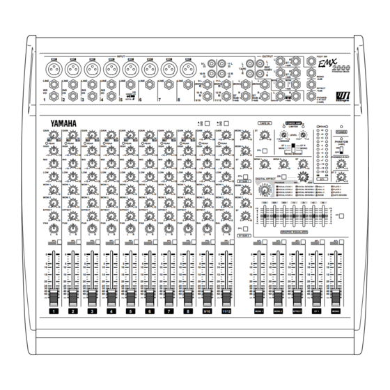
- Page 1 Owner’s Manual LINE LINE LINE GAIN GAIN GAIN –34 –34 –34 –16 –60 –16 –60 –16 –60 PEAK PEAK PEAK HIGH HIGH HIGH –15 –15 –15 –15 –15 –15 –15 –15 –15 MONI 1 MONI 1 MONI 1 MONI 2 MONI 2 MONI 2 EFFECT...
- Page 2 FCC requirements. Modifications not expressly approved by Yamaha may void your authority, granted by the FCC, to use the product. 2. IMPORTANT: When connecting this product to accessories and/or another product use only high quality shielded cables.
- Page 3 Introduction Thank you for purchasing the Yamaha EMX2000 Powered Mixer. In order to take full advantage of the EMX2000 and enjoy long, trouble-free performance, please read this owner’s manual carefully, and keep it in a safe place for future reference.
-
Page 4: Table Of Contents
As a band PA ...14 As a conference/entertainment hall sound system ...15 Using a subwoofer ...16 Refer all maintenance to qualified Yamaha service personnel. Opening the case and/or tampering with the internal circuitry voids the warranty. 5. Always power off before making connec-... -
Page 5: Front And Rear Panel
Front and rear panel Control panel Channel control section In this section, you can adjust equalization (fre- quency response), volume level, effect and moni- tor output levels for the input signal of each channel. GAIN GAIN –34 –16 –60 PEAK PEAK HIGH HIGH... - Page 6 Effect control (EFFECT) For each channel, this controls the amount of sig- nal that is sent to the EFFECT bus. The signal of the EFFECT bus is sent to the EFFECT jack (input/output panel A). It is also sent to the built-in effect when the ON switch P in the EFFECT section is turned on.
-
Page 7: Tape In Section
Master control section In this section, you can adjust the final level of the outputs. MONI 1 MONI 2 EFFECT ST 1 MONI 1 (monitor 1) fader The MONI 1 fader adjusts the final level of the signal sent from the MONITOR 1 bus to the MONI 1 jack (input/output panel 9 ). -
Page 8: Graphic Equalizer Section
Digital effect section This section enables you to turn the built-in digi- tal effect on/off and select the effect type. MONI 1 MONI 2 DIGITAL EFFECT PROGRAM VOCAL ECHO 1 VOCAL REVERB 1 VOCAL ECHO 2 VOCAL REVERB 2 VOCAL ECHO 3 VOCAL REVERB 3 VOCAL ECHO 4 VOCAL REVERB 4... - Page 9 LEVEL controls These knobs enable you to adjust the level of the signals input from the mixer section to the power amp section. Rotating the knob clockwise will raise the level of the input signal. Use a screw- driver of a width of 3mm or less to adjust the knob.
-
Page 10: Input/Output Panel
Input/output panel INPUT LINE LINE LINE LINE LINE Channel input jacks (MIC, LINE) 1~8 These are the input jacks for channels 1~8. By using the GAIN control (control panel 1) you can connect any of the jacks to a wide range of sources, from mics to line-level devices (including synthesizers and rhythm machines). - Page 11 FOOT SW (foot switch) jack A separately sold Yamaha FC5 foot switch can be connected to this jack so you can use your foot to switch the built-in digital effect on/off. The digi- tal effect ON switch on the front panel must be set to ON in order to use a foot switch.
-
Page 12: Rear Panel
Rear panel SPEAKERS BRIDGE SPEAKERS (speaker output) jacks Speakers can be connected to these jacks. The type of signals output, the number of speak- ers you can connect, and acceptable impedance differ depending on the setting of the Power amp select switch (control panel V). -
Page 13: Connections
Connections When connecting various devices, be sure to use cables and plugs of the appropriate standard. Connecting speakers There are three ways in which speakers can be connected to the EMX2000. Connecting a single speaker to each of the L and R jacks: A single speaker each can be connected to either jack 1 or jack 2 of SPEAKERS L and of SPEAK- ERS R. -
Page 14: Basic Operation
Basic operation Connecting microphones and instruments Before connecting mics or instruments, make sure that the power of all equip- ment (where applicable) is turned off. Also make sure that each channel fader and the faders in the master section are turned down. -
Page 15: Example Setups
Example setups This section provides some ways in which the EMX2000 can be used, and explains connections and operation. As a band PA Here is an example of using the EMX2000 as a small PA for a band. In this example, the monitor speakers are being sent a mix that is independent of the MAIN speaker mix. -
Page 16: As A Conference/Entertainment Hall Sound System
As a conference/entertainment hall sound system Here is an example of using the EMX2000 as a conference or entertainment hall sound system. Microphone LINE LINE LINE LINE GAIN GAIN GAIN GAIN –34 –34 –34 –34 –16 –60 –16 –60 –16 –60 –16 –60... -
Page 17: Using A Subwoofer
EFFECT –12 –12 GRAPHIC EQUALIZER ST SUB 2 9/10 11/12 MONI 1 MONI 2 EFFECT ST 1 MONO R 1/2 Yamaha Crossover network PN90 TO POWER LEFT AMP INPUTS INPUTS HIGH RIGHT LEFT RIGHT LEFT ST L ST R MONI 1... -
Page 18: Specifications
Specifications General specifications STEREO: 200 W+200 W/4 Maximum output power BRIDGE: 400 W/8 20 Hz~20 kHz +1 dB, –3 dB @1 W output into 8 (SPEAKER OUT) Frequency response 20 Hz~20 kHz +1 dB, –3 dB @+4 dB output into 600 (ST OUT, MONO OUT, EFFECT SEND, MONITOR OUT) Less than 0.5% @20 Hz~20 kHz, 100 W output into 4 (SPEAKER OUT) -
Page 19: Input Specifications
Input specifications Gain Actual load Input terminals trim impedance MIC INPUT (1–8) LINE INPUT 50 k (1–8) ST INPUT 10 k (9–12) ST SUB IN (1, 2) 10 k TAPE IN (L, R) 10 k CH INSERT IN (1–4) 10 k POWER AMP IN (L, R) 10 k 1. -
Page 20: Dimensions
Dimensions W: 480 Unit: mm EMX2000—Owner’s Manual... -
Page 21: Block/Level Diagram
Block/Level Diagram +48V PEAK PHANTOM 3 Band EQ INPUT 1–4 LINE GAIN HIGH INS I/O PEAK 3 Band EQ INPUT 5–8 LINE GAIN LOW MID HIGH PEAK 9L,11L 3 Band EQ (MONO) 3 Band EQ 10R,12R INPUT 9/10 11/12 9L,11L 10R,12R (MONO) ST SUB 1,2... - Page 22 YAMAHA CORPORATION VZ42360 R1 1 IP 24 Pro Audio Division, #18/3 P.O. Box 3, Hamamatsu, 430-8651, Japan NP Printed in Taiwan...