Table of Contents
Quick Links
Chapters
Table of Contents

Related Manuals for Hitachi ZW180


Summary of Contents for Hitachi ZW180
- Page 3 • Be sure to thoroughly read this manual for correct (Note: Do not tear off the form. Copy it for us- product information and service procedures. age.): Publications Marketing & Product Support Hitachi Construction Machinery Co. Ltd. TEL: 81-29-832-7084 FAX: 81-29-831-1162 ADDITIONAL REFERENCES •...
- Page 4 INTRODUCTION SAFETY ALERT SYMBOL AND HEADLINE NOTATIONS In this manual, the following safety alert symbol and • CAUTION: signal words are used to alert the reader to the Indicated potentially hazardous situation which could, potential for personal injury of machine damage. if not avoided, result in personal injury or death.
- Page 5 Group 4 Wheel Loader Test Group 5 Troubleshooting A Group 5 Component Test Group 6 Troubleshooting B Group 6 Adjustment Group 7 Troubleshooting C Group 8 Electrical System Inspection COPYRIGHT (C) 2007 Hitachi Construction Machinery Co., Ltd. Tokyo, Japan All rights reserved...
- Page 6 WORKSHOP MANUAL SECTION 1 GENERAL INFORMATION SECTION 3 BASE MACHINE (TRAVEL Group 1 Precautions for Disassem- SYSTEM) bling and Assembling Group 1 Tire Group 2 Tightening Torque Group 2 Drive Unit Group 3 Painting Group 3 Axle Group 4 Bleeding Air from Hydrau- Group 4 Propeller Shaft lic Oil Tank Group 5 Brake Valve...
-
Page 7: Table Of Contents
SECTION 1 GENERAL ―CONTENTS― Group 1 Specifications Group 3 Component Specifications Specifications ...........T1-1-1 Engine............T1-3-1 Engine Accessories ........T1-3-5 Group 2 Component Layout Hydraulic Component .......T1-3-7 Main Component (Overview) ....T1-2-1 Electrical Component ......T1-3-12 Main Component (Upperstructure) ...T1-2-2 Main Component Layout (Travel System) ........T1-2-3 Electrical System (Overview) ....T1-2-4 Electrical System (In Cab) ......T1-2-5 Engine and Fan Pump ......T1-2-10... - Page 8 (Blank) 4GDT-1-2...
-
Page 9: Specifications
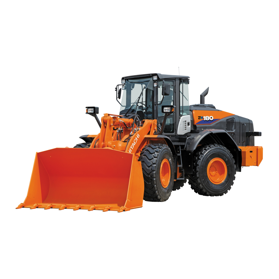
GENERAL / Specification SPECIFICATIONS M4GB-12-002 − Type ZW180 Bucket Capacity: heaped 2.8 (3.7) 〔BOC〕 m³ (yd³) Operating Weight 14200 (31300) kg (lb) Rated Loading Weight 4480 (9877) kg (lb) Cummins QSB 6.7 − Engine 129.0 kW/2200 min (175 PS/2200 rpm) ⋅... - Page 10 GENERAL / Specification (Blank) T1-1-2...
-
Page 11: Main Component (Overview)
GENERAL / Component Layout MAIN COMPONENT (OVERVIEW) T4GD-01-02-005 1 - Bucket Head Light 7 - Rear Working Light 10 - Lift Arm Cylinder 2 - Bell Crank Front Working Light 8 - Rear Combination Light 11 - Lift Arm (Turn Signal, Hazard Light, Clearance Light, Brake Light and Back Light) 3 - Bucket Cylinder... -
Page 12: Main Component (Upperstructure)
GENERAL / Component Layout MAIN COMPONENT (UPPERSTRUCTURE) T4GD-01-02-006 1 - Charging Block 6 - Control Valve 11 - Fuel Tank 16 - Oil Cooler 2 - Pilot Valve 7 - Stop Valve 12 - Intercooler 17 - Muffler 3 - Brake Valve 8 - Pilot Shut-Off Valve 13 - Torque Converter Cooler 18 - Coolant Reservoir... -
Page 13: Main Component Layout (Travel System)
GENERAL / Component Layout MAIN COMPONENT LAYOUT (TRAVEL SYSTEM) T4GD-01-02-007 Front Axle Pump Device Rear Axle Steering Accumulator Propeller Shaft (Front) Transmission Propeller Shaft (Rear) Brake Pressure Sensor Steering Cylinder T1-2-3... -
Page 14: Electrical System (Overview)
GENERAL / Component Layout ELECTRICAL SYSTEM (OVERVIEW) In Cab (Refer to T1-2-5.) Engine and Fan Pump (Refer to T1-2-10.) Pump Device (Refer to T1-2-11.) Drive Unit (Refer to T1-2-11.) T4GD-01-02-008 1 - Hydraulic Oil Level Battery Emergency Steering Pump 10 - Lift Arm Proximity Switch Switch Delivery Pressure Switch 2 - Air Filter Restriction... -
Page 15: Electrical System (In Cab)
GENERAL / Component Layout ELECTRICAL SYSTEM (IN CAB) Monitor and Switches (Refer to T1-2-8.) Right Consol (Refer to T1-2-7.) T4GB-01-02-006 Controller and Relays (Refer to T1-2-6.) 1 - Radio 3 - Speaker 5 - Brake Light Switch 6 - Front Wiper Motor 2 - Auxiliary Switch Panel 4 - Rear Wiper Motor (Optional) - Page 16 GENERAL / Component Layout Controller and Relays T4GB-01-02-006 T4GD-01-02-002 T4GC-01-02-002 Flusher Relay 9 - Parking Brake Relay 1 17 - Emergency Steering Relay 25 - Overheat Relay (B-R2) (A-R10) Option Controller 10 - Parking Brake Relay 2 18 - Turn Signal Relay (Left) 26 - Engine Oil Pressure Relay (Optional) (A-R9)
- Page 17 GENERAL / Component Layout Right Consol T4GD-01-02-003 T4GB-01-02-023 DSS (Down Shift) 6 - Auxiliary Control Lever 11 - Emergency Steering Check 15 - FNR Selector Switch Switch (Optional) Switch (Optional) Bucket Control Lever 7 - Quick Coupler Switch 12 - Fan Reversing Switch 16 - Cigar Lighter (Optional) Lift Arm Control Lever...
- Page 18 GENERAL / Component Layout Monitor and Switches T4GD-01-02-003 T4GB-01-02-024 1 - Monitor Panel 5 - Work Mode Selector Switch 9 - Front Wiper Switch 12 - Rear Wiper Switch (Refer to T1-2-9.) 2 - Driving Mode Switch 6 - Clutch Cut Position Switch 10 - FNR Lever/Shift Switch 13 - Working Light Switch 3 - Turn Signal Lever /Head...
- Page 19 GENERAL / Component Layout Monitor Panel T4GD-01-02-001 23 22 1 - Engine Coolant 10 - Parking Brake Indicator 19 - Discharge Warning Indicator 28 - Engine Failure Indicator Temperature Gauge 2 - Transmission Oil 11 - Clearance Light Indicator 20 - Lever Steering Indicator 29 - Overheat Indicator Temperature Gauge (Optional)
-
Page 20: Engine And Fan Pump
GENERAL / Component Layout ENGINE AND FAN PUMP View A T4GD-01-02-009 1 - Common Rail Pressure 5 - Ambient Pressure Sensor 9 - Engine Speed Sensor 12 - Starter Sensor (Crankshaft) 2 - Intake Manifold Pressure / 6 - Engine Oil Pressure Switch 10 - Engine Oil Filter 13 - High-Pressure Pump Intake Manifold Temperature... -
Page 21: Pump Device
GENERAL / Component Layout PUMP DEVICE T4GB-01-02-009 DRIVE UNIT T4GD-01-02-004 1 - Main Pump 6 - Steering Relief Valve 11 - Transmission Output 16 - 2nd Speed Clutch Solenoid Speed Sensor Valve 2 - Regulator 7 - Torque Converter Input 12 - Transmission Middle Shaft 17 - 3rd Speed Clutch Solenoid Speed Sensor... -
Page 22: Control Valve
GENERAL / Component Layout CONTROL VALVE T4GB-01-02-027 1 - Overload Relif Valve 3 - Overload Relief Valve 4 - Make-Up Valve 5 - Main Relief Valve (Lift Arm: Bottom Side) (Bucket: Rod Side) (Lift Arm: Rod Side) 2 - Overload Relief Valve (Bucket: Bottom Side) T1-2-12... -
Page 23: Ride Control Valve(Optional)
GENERAL / Component Layout RIDE CONTROL VALVE (OPTIONAL) CHARGING BLOCK T4GB-01-02-013 T4GB-01-02-014 FAN MOTOR T4GB-01-02-012 1 - Overload Relief Valve Service Brake Accumulator 8 - Pilot Relief Valve 11 - Reverse Control Solenoid (Front) Valve 2 - Ride Control Solenoid Service Brake Accumulator 9 - Pump Torque Control 12 - Relief Valve... -
Page 24: Steering Valve
GENERAL / Component Layout STEERING VALVE T4GB-01-02-020 EMERGENCY STEERING PUMP (OPTIONAL) T4GB-01-02-010 1 - Overload Relief Valve Electric Motor 5 - Check Valve Relief Valve 2 - Overload Relief Valve Gear Pump T1-2-14... -
Page 25: Engine
GENERAL / Component Specifications ENGINE Manufacturer ..........Cummins Inc. Model............QSB6.7 Type............Diesel, 4 Cycle, Water Cooled, Over Head Valve, Inline, Direct Injection, Turbo Charged Cyl. NO. - Bore×Stroke......6-107 mm×124 mm (4.21 in×4.88 in) Piston Displacement......... 6690 cm (408 in Rated Output .......... - Page 26 GENERAL / Component Specifications LUBRICATION SYSTEM Lubrication Pump Type......Trochoid Type Oil Filter ............ Strata Pore (Plastic fiber) / Spin-on Type Oil Cooler ..........Water Cooled Type STARTING SYSTEM Motor ............Magnetic Pinion Shift Reduction Type Voltage/Output.......... 24 V⋅7.8 kW PREHEAT SYSTEM Preheating Method ........
- Page 27 GENERAL / Component Specifications PERFORMANCE IMPORTANT: This list shows design specifications, which are not servicing standards. Fuel Consumption Ratio......233±12 g/kW⋅h (171±9 g/PS⋅h) @ 2200 min (rpm) Maximum Output Torque ......763±39 N⋅m (77.8±4 kgf⋅m) @ at approx. 1400 min (rpm) No Load Speed.........
- Page 28 GENERAL / Component Specifications Engine Performance Curve (QSB6.7) Torque (N⋅m) Output (kW) Engine Speed min (rpm) T4GD-01-03-001 T1-3-4...
-
Page 29: Engine Accessories
GENERAL / Component Specifications ENGINE ACCESSORIES RADIATOR ASSEMBLY Type............Radiator, Inter Cooler and Torque Converter Cooler Tandem Type Assembly Oil Cooler Radiator Oil Cooler Capacity............ 9.9 L (2.6 US gal) 5.5 L (1.4 US gal) Air-Tight Test Pressure ......100 kPa (1.0 kgf/cm , 14.5 psi) 1500 kPa (15 kgf/cm , 217 psi)) - Page 30 GENERAL / Component Specifications HYDRAULIC FAN PUMP Model............SGP1A25D2H1 Type............Fixed Displacement Type Gear Pump Maximum Flow (Theoretical Value) ..55 L/min (14.51 US gpm) HYDRAULIC FAN MOTOR Relief Set Pressure ........20.6 MPa (210 kgf/cm ) @ 5 L/min (1.32 US gpm) SOLENOID VALVE Function............
-
Page 31: Hydraulic Component
GENERAL / Component Specifications HYDRAULIC COMPONENT MAIN PUMP Type............Bent Axis Type Variable Displacement Axial Plunger Pump Maximum Flow (Theoretical Value) ..209 L/min (55 US gpm) REGULATOR Type............Hydraulic Pressure Operated Type PRIORITY VALVE Relief Set Pressure ........27.4 MPa (280 kgf/cm ) @ 70 L/min (18.5 US gpm) PILOT PUMP Model............ - Page 32 GENERAL / Component Specifications RIDE CONTROL VALVE (OPTIONAL) Type............Pilot Pressure Operated Type Overload Relief Set Pressure....39.2 MPa (400 kgf/cm ) @ 50 L/min (13 US gpm) Charge Cut Pressure........ 11.3 MPa (115 kgf/cm RIDE CONTROL ACCUMULATOR (OPTIONAL) Capacity............ 4 L (244 in Charging Pressure ........
- Page 33 GENERAL / Component Specifications STEERING PILOT VALVE Type............Orbitroll Type Gerotor Capacity ........96 cm /rev (5.9 in /rev) STEERING ACCUMULATORv Capacity............ 0.2 L (12 in Charging Pressure ........8 MPa (82 kgf/cm BRAKE VALVE Brake Pressure......... 3.9 MPa (40 kgf/cm T1-3-9...
- Page 34 GENERAL / Component Specifications • Travel System TRANSMISSION Type............Counter Shaft Type Gear Ratio ..........Forward 1st : 3.324 Forward 2nd : 1.963 Forward 3rd : 1.022 Forward 4th : 0.603 Reverse 1st : 3.324 Reverse 2nd : 1.963 Reverse 3rd : 1.022 Reverse 4th : 0.603 Parking Brake Release Pressure .....
- Page 35 GENERAL / Component Specifications • Front Attachment CYLINDER Lift Arm (Left/Right) Bucket Steering Rod Diameter ........... 75 mm (2.95") 85 mm (3.35") 45 mm (1.77") Cylinder Bore..........125 mm (4.92") 150 mm (5.91") 70 mm (2.76") Stroke ............765 mm (2'6") 495 mm (1'8") 442 mm (1'5") Fully Retracted Length ......
-
Page 36: Electrical Component
GENERAL / Component Specifications ELECTRIC COMPONENT ENGINE OIL PRESSURE SENSOR Operation Pressure ........41.4 kPa (0.4 kgf/cm OVER HEAT SWITCH Operation Temperature ......105±2 ° C (221±2 °F) COOLANT TEMPERATURE SENSOR (For Coolant Temperature Gauge) Operation Temperature ......25 to 120 °C (77 to 248 °F) AIR FILTER RESTRICTION SWITCH Operation Pressure ........ - Page 37 GENERAL / Component Specifications ILLUMINATION Work Light ..........: Halogen 24 V, 70 W Cab Light ..........: 24 V, 10 W Head Light ..........: Halogen 24 V、75/70 W Turn Signal Light ........: Front : 24 V, 25 W :Rear : 24 V, 21 W Clearance Light ........
- Page 38 GENERAL / Component Specifications (Blank) T1-3-14...
- Page 39 M E M O ........................................................................................................................................................................................................................................................................................................................................................................................................................................................................................................................................................................................................................................................................................................................................................................................................................................................................................................................................................................................................................
- Page 40 M E M O ........................................................................................................................................................................................................................................................................................................................................................................................................................................................................................................................................................................................................................................................................................................................................................................................................................................................................................................................................................................................................................
- Page 41 SECTION 2 SYSTEM —CONTENTS— Group 1 Control System Group 4 Electrical System General ............T2-1-1 Outline .............T2-4-1 Engine Control .........T2-1-6 Main Circuit ..........T2-4-2 Pump Control .........T2-1-15 Electric Power Circuit .......T2-4-3 Transmission Control ......T2-1-20 Indicator Light Check Circuit.....T2-4-4 Other Controls........T2-1-41 Accessory Circuit........T2-4-5 Control by Electric and Hydraulic Preheat Circuit .........T2-4-6 Combined Circuit ........T2-1-51...
- Page 42 (Blank) 4GDT-2-2...
-
Page 43: General
SYSTEM / Control System GENERAL There are four controllers as shown below with MC – MC, ECM and the monitor unit display indications on Main Controller – installed at their center. the monitors and make various controls of the vehicle body by using the analog signals received by each •... - Page 44 SYSTEM / Control System MC, ECM and Monitor Unit are used for various op- eration controls of the body. • The analog input signals from the sensors and switches attached to devices other than the engine and monitor unit as well as the analog output signals from the solenoid valves are transmitted to MC, and converted into the digital signals to be uploaded on CAN.
- Page 45 SYSTEM / Control System Injectors Sensors and Switches for Ve- hicle Body Transmission Engine Solenoid Valves for Vehicle Body Sensors and Switches Sensor Switches for Cab and Monitor Solenoid Valves Monitor Unit Relays for Sensors and Switches Switches for Traveling Light Emitting Diode Dr.
- Page 46 SYSTEM / Control System The sensors and switches to detect the signals for various operation controls and their controllers are as shown below. Input Signals Operation Control • → Accelerator Pedal Sensor Engine Control • → Travel Mode Switch →Accelerator Pedal Control •...
- Page 47 SYSTEM / Control System Input Signal Operation Control • FNR Lever → Transmission Control • Shift Switch → →Neutral Control • Downshift Switch → →FNR Lever Priority Control • Upshift Switch → →FNR Selector Control While Traveling • Hold Switch →...
-
Page 48: Engine Control
SYSTEM / Control System ENGINE CONTROL The engine controls consist of the followings. • Accelerator Pedal Control • Auto-Warming Up Control • Engine Torque Control T2-1-6... - Page 49 SYSTEM / Control System Engine Control System Layout Work Mode Selector Switch Accelerator Pedal Hydraulic Oil Temperature Accelerator Pedal Sensor Sensor Main Pump Delivery Pressure Sensor Shift Switch Transmission Engine Torque Converter Input Speed Sensor Torque Converter Output Monitor Speed Sensor Unit T4GC-02-01-002 Engine Coolant...
- Page 50 SYSTEM / Control System Accelerator Pedal Control Purpose: To control the engine speed in response to stepping amount of the accelerator pedal. Actual Engine Speed Operation: 1. MC converts the input value from the accelerator Fast Idle pedal into the target engine speed and transmits it to ECM.
- Page 51 SYSTEM / Control System Accelerator Pedal Accelerator Pedal Sensor Transmission Engine Monitor Unit T4GC-02-01-003 T2-1-9...
- Page 52 SYSTEM / Control System Auto-Warming Up Control Purpose: To warm up the engine in response to the Actual hydraulic oil temperature automatically. Engine Speed Operation: Fast Idle 1. At start of the engine, if the hydraulic oil tem- perature is 0°C (32°F) or below, MC transmits the Auto-Warming signal that the engine slow idle speed is set at Up Speed...
- Page 53 SYSTEM / Control System Hydraulic Oil Temperature Sensor Transmission Engine Monitor Unit Engine Coolant Temperature Sensor T4GC-02-01-004 T2-1-11...
- Page 54 SYSTEM / Control System Engine Torque Control Purpose: To improve fuel consumption rate by Engine Torque changing the torque curve in response to the input signals from the work mode selector switch, shift switch and vehicle speed sen- Operation: 1. When MC receives the signal of the selected work mode, MC detects the shift point.
- Page 55 SYSTEM / Control System Work Mode Selector Switch Shift Switch Transmission Engine Monitor Unit T4GD-02-01-007 NOTE: The illustration shows the signal flow while mode L of work mode selector switch and speed 1 of the shift switch are selected. T2-1-13...
- Page 56 SYSTEM / Control System (Blank) T2-1-14...
-
Page 57: Pump Control
SYSTEM / Control System PUMP CONTROL The pump controls consist of the followings. • Standard Torque Control • Torque Decrease Control Pump Control System Layout Accelerator Pedal Accelerator Pedal Sensor Hydraulic Oil Temperature Sensor Main Pump Delivery Pressure Sensor Transmission Engine Main Pump Pump Torque Control... - Page 58 SYSTEM / Control System Standard Torque Control Purpose: To utilize engine output power by changing pump delivery flow rate in response to in- crease or decrease of engine speed and hydraulic oil temperature effectively. Operation: 1. When the accelerator pedal is depressed, MC calculates the target engine speed.
- Page 59 SYSTEM / Control System Accelerator Pedal Accelerator Pedal Sensor Hydraulic Oil Temperature Sensor Transmission Engine Main Pump Pump Torque Control Regulator Solenoid Valve Monitor Unit T4GD-02-01-009 T2-1-17...
- Page 60 SYSTEM / Control System Torque Decrease Control Purpose: To utilize engine output power by changing pump delivery flow rate in response to in- crease or decrease of the engine speed due to traveling load effectively. Operation: 1. When the accelerator pedal is depressed, MC calculates the target engine speed.
- Page 61 SYSTEM / Control System Accelerator Pedal Accelerator Pedal Switch Hydraulic Oil Temperature Sensor Main Pump Delivery Pressure Switch Transmission Engine Main Pump Pump Torque Control Regulator Solenoid Valve Torque Converter Output Speed Sensor Monitor Torque Converter Unit Input Speed Sensor T4GD-02-01-010 T2-1-19...
-
Page 62: Transmission Control
SYSTEM / Control System TRANSMISSION CONTROL The transmission controls consist of the followings. • Neutral Control • FNR Lever Priority Control • Forward/Reverse Selector Control While Travel- • Manual Speed Shift Control • Automatic Speed Shift Control • Downshift Control •... - Page 63 SYSTEM / Control System Transmission Control System Layout Key Switch Travel Mode Switch Brake Pressure Accelerator Sensor Pedal Sensor Brake Pedal Accelerator Pedal 1-4L 2-4N 1-4H Reverse Clutch Forward Clutch Cut Transmission Solenoid Valve Clutch Solenoid Position Switch Middle Shaft Valve Sensor Transmission...
- Page 64 SYSTEM / Control System Neutral Control Purpose: To protect transmission by restricting clutch IMPORTANT: Be careful that in case the parking connection despite operation of FNR lever or brake pressure sensor is abnormal, FNR switch while applying the parking traveling is possible even if the brake.
- Page 65 SYSTEM / Control System Forward Clutch Reverse Clutch Solenoid Valve Solenoid Valve Engine Transmission Parking Brake Pressure Sensor Monitor Unit Parking Brake Solenoid Valve Parking Brake FNR Lever FNR Switch FNR Selector Parking Brake T4GC-02-01-010 Switch Switch NOTE: The illustration shows the signal flow in case forward of the FNR lever have been selected with the parking brake switch OFF (Transmitting brake release signal).
- Page 66 SYSTEM / Control System FNR Lever Priority Control Purpose: To smoothen danger-preventive function in forward/reverse operation by giving priority to the signal from FNR lever over the signal from FNR switch Operation: 1. In case the FNR lever is operated while traveling by using the FNR switch, MC disables operation of the FNR switch, and makes forward/reverse control by the input signal from the FNR lever.
- Page 67 SYSTEM / Control System Forward Clutch Reverse Clutch Solenoid Valve Solenoid Valve Engine Transmission Monitor Unit FNR Lever FNR Switch FNR Selector Switch T4GC-02-01-011 NOTE: The illustration shows the signal flow in case forward of the FNR selector lever has been selected while traveling reverse of the FNR lever.
- Page 68 SYSTEM / Control System Forward/Reverse Selector Control while Traveling Purpose: To protect the transmission by preventing forward/reverse selector unless the vehicle speed is lowered than the set speed when traveling over the set speed. Operation: 1. In case the FNR lever is turned to reverse while traveling forward speed is higher than the allow- able speed of FNR clutch selection, MC reduces the vehicle speed shift by sending the speed shift...
- Page 69 SYSTEM / Control System Accelerator Pedal Brake Pressure Sensor Sensor Accelerator Pedal Brake Pedal Shift Switch Forward Clutch Reverse Clutch Solenoid Valve Solenoid Valve Engine 1 2 3 Speed Shift Solenoid Valve Vehicle Speed Sensor Transmission Monitor Unit FNR Lever FNR Switch FNR Selector Switch T4GC-02-01-012...
- Page 70 SYSTEM / Control System Manual Speed Shift Control Purpose: To shift the speed manually NOTE: MC is programmed in order to dtermine the vehicle speed ranges to change to the re- Operation: spective speed shifts. 1. When manual (M) of the travel mode switch is selected, MC is provided with voltage of 1V.
- Page 71 SYSTEM / Control System Travel Mode Switch Accelerator Pedal Brake Pressure Sensor Sensor Accelerator Brake Pedal Pedal 1-4L 2-4N 1-4H Shift Switch Forward Clutch Solenoid Valve Engine 1 2 3 Speed Shift Solenoid Valve Vehicle Speed Sensor Monitor Transmission Unit FNR Lever FNR Switch FNR Selector...
- Page 72 SYSTEM / Control System Automatic Speed Shift Control Purpose: To shift the speed automatically with three 4. MC transmits the signal to the speed shift solenoid kinds of timing selection of automatic speed valve in response to the output value each time of shift change the torque converter input speed sensor, torque converter output speed sensor, vehicle speed...
- Page 73 SYSTEM / Control System Travel Mode Switch Accelerator Pedal Brake Pressure Sensor Sensor Brake Pedal Accelerator Pedal 1-4L 2-4N 1-4H Shift Switch Forward Clutch Solenoid Valve Transmission 1 2 3 Engine Speed Shift Solenoid Valve Vehicle Speed Sensor Monitor Unit Torque Converter Torque Converter FNR Lever...
- Page 74 SYSTEM / Control System Downshift Control Purpose: To lower the speed shift by pushing the 8. In case of the following, the downshift switch con- switch installed at the right console. trol is canceled. • Operation of the FNR lever or the FNR switch •...
- Page 75 SYSTEM / Control System Travel Mode Switch Accelerator Pedal Sensor Brake Pressure Sensor Brake Pedal Accelerator Pedal 1-4L 2-4N 1-4H Shift Switch Transmission Forward Clutch Middle Shaft Sensor Solenoid Valve Reverse Clutch Solenoid Valve Engine 1 2 3 Speed Shift Solenoid Valve Vehicle Speed Sensor Transmission...
- Page 76 SYSTEM / Control System Upshift Control Purpose: To raise the speed shift by putting the left NOTE: The shift switch has two switches, and their hand on the steering wheel and pushing the combination of ON varies depending on switch installed at the right console each speed shift.
- Page 77 SYSTEM / Control System Travel Mode Switch Accelerator Pedal Brake Pressure Sensor Sensor Brake Pedal Accelerator Pedal 1-4L 2-4N 1-4H Shift Switch Forward Clutch Solenoid Valve Reverse Clutch Solenoid Valve 1 2 3 Engine Speed Shift Solenoid Valve Transmission Monitor Unit FNR Lever FNR Switch...
- Page 78 SYSTEM / Control System Clutch Cut Control Purpose: To release the FNR clutch of the transmis- 5. In case the brake pressure is lowered below the sion in order to make the most of the engine set pressure by reducing the depressing amount torque by operating the brake during opera- of the brake pedal, the signal transmitted to the tion of the front attachment.
- Page 79 SYSTEM / Control System Brake Pressure Brake Pedal Sensor Clutch Cut Position Switch Forward Clutch Solenoid Valve Reverse Clutch Solenoid Valve Engine Transmission Monitor Unit T4GC-02-01-017 NOTE: The illustration shows the signal flow in case the brake pedal has been depressed in mode S of the clutch cut position switch.
- Page 80 SYSTEM / Control System Speed Shift Holding Control Purpose: To hold the speed shift while towing or trav- NOTE: The shift switch has two switches, and their eling uphill. combination of ON varies depending on each speed shift. The controller judges Operation: which speed shift has been selected by the combination of the two input signals.
- Page 81 SYSTEM / Control System Key Switch Travel Mode Switch Accelerator Pedal Brake Pressure Sensor Sensor Accelerator Pedal Brake Pedal 1-4L 2-4N 1-4H Shift Switch Forward Clutch Solenoid Valve Engine 1 2 3 Speed Shift Solenoid Valve Transmission Monitor Unit FNR Lever FNR Switch DOWN HOLD...
- Page 82 SYSTEM / Control System (Blank) T2-1-40...
-
Page 83: Other Controls
SYSTEM / Control System OTHER CONTROLS The other controls consist of the following. • Hydraulic Fan Cooling Control • Hydraulic Fan Cleaning Control • Transmission Failure Indicator Control • FNR Switch Enable Indicator Control • Reverse Traveling Alarm Control • Parking Brake Indicator Control T2-1-41... - Page 84 SYSTEM / Control System Hydraulic Fan Cooling Control Purpose: To improve fuel consumption rate and noise reduction by restricting the hydraulic fan speed in response to each oil temperature and coolant temperature. Operation: 1. When the engine is started, the fan pump rotates and delivers oil to the fan motor.
- Page 85 SYSTEM / Control System At oil temperature or coolant temperature above the set temperature (Uncontrolled speed operation) Fan Motor Flow Rate Control Valve Hydraulic Oil Tank Flow Rate Control Hydraulic Oil Temperature Sensor Solenoid Valve Fan Pump Engine Coolant Tem- perature Sensor Fresh Air Temperature...
- Page 86 SYSTEM / Control System Hydraulic Fan Cleaning Control Purpose: To clean the radiator and oil cooler by re- NOTE: Temporarily turn the reverse rotation control versing the hydraulic fan in order to blow solenoid valve ON when the key switch is away dust in case cleaning of the radiator turned ON as the spool maybe stuck in and oil cooler are needed.
- Page 87 SYSTEM / Control System During cooling operation (Normal rotation) Fan Motor Reverse Rotation Spool Reverse Rotation Control Solenoid Valve Trans- Engine mission Hydraulic Oil Tank T4GB-02-01-007 During cleaning operation (Reverse rotation) Fan Motor Reverse Rotation Spool Reverse Rotation Control Solenoid Valve Hydraulic Oil Tank Trans-...
- Page 88 SYSTEM / Control System Transmission Failure Indicator Control • Purpose: To light the transmission failure indicator on Torque converter input speed sensor • the monitor unit for protection of the trans- Torque converter output speed sensor • mission in case of disorder of parts likely to Vehicle speed sensor •...
- Page 89 SYSTEM / Control System FNR Switch Enable Indicator Control Purpose: To light the FNR switch enable indicator on NOTE: In case the FNR lever is operated while the monitor when the FNR switch is effec- traveling by using the FNR switch, input to tive.
- Page 90 SYSTEM / Control System Reverse Traveling Alarm Control (Refer to the SYSTEM/Electric System group.) Purpose: To sound the alarm buzzer when reverse of the FNR lever or the FNR switch is selected. Operation: 1. When reverse of the FNR lever or the FNR switch is selected, MC grounds the terminal from the reverse light relay.
- Page 91 SYSTEM / Control System Parking Brake Indicator Control Purpose: To light the parking brake indicator on the NOTE: The parking brake of the vehicle body is monitor unit during parking brake operation. released if pilot pressure is routed. Operation: NOTE: As for operation circuit of the parking brake, 1.
- Page 92 SYSTEM / Control System (Blank) T2-1-50...
-
Page 93: Control By Electric And Hydraulic Combined Circuit
SYSTEM / Control System CONTROL BY ELECTRIC AND HYDRAU- LIC COMBINED CIRCUIT The electric and hydraulic combined circuit has the following controls. • Ride Control (Optional) • Bucket Auto-Leveler Control • Lift Arm Float Control • Lift Arm Kick-Out Control •... - Page 94 SYSTEM / Control System Ride Control (Optional) Purpose: To reduce fatigue of the operator by orga- nizing a damper circuit in the lift arm cylinder and reducing shock when traveling on rough roads Operation: 1. When the ride control switch is turned ON, MC makes the ride control effective and the ride con- trol indicator on the monitor is lit.
- Page 95 SYSTEM / Control System Lift Arm Cylinder Trans- Engine mission To Control Valve Monitor Vehicle Speed Sensor Unit Ride Control Accumulator Ride Control Indicator Ride Control Valve Relief Valve Ride Control Switch Ride Control Solenoid Valve Spool Pilot Pump Hydraulic Oil Tank T4GD-02-01-003 T2-1-53...
- Page 96 SYSTEM / Control System Bucket Auto-Leveler Control Purpose: Automatically to tilt the bucket at a proper angle (horizontal) to start digging when re- turning the bucket to the tilting position Operation: 1. When bucket dump operation is carried out, the bar is located in front of the bucket proximity switch.
- Page 97 SYSTEM / Control System Bucket Cylinder Bucket Proximity Switch Leveler Relay From Fuse #6 of Fuse Box B Control Valve Bucket Pilot Valve Bucket Electromagnet on Bucket Tilting Side Pilot Pump Lift Arm Hydraulic Oil Main Tank T4GD-02-01-001 Pump T2-1-55...
- Page 98 SYSTEM / Control System Lift Arm Float Control Purpose: Free to raise and lower the lift arm in re- sponse to the external force in order to re- move snow and clean road. Operation: 1. When the lift arm control on lever is moved to the floating position (farther position than the lift arm lowering position), the lift arm control lever is re- tained by the electromagnet on the lift arm lower-...
- Page 99 SYSTEM / Control System Lift Arm Cylinder Bottom Side Port Rod Side Port Control Valve From Fuse #6 of Fuse Box B Electromagnet on Lift Arm Lowering Side Bucket Lift Arm Pilot Valve Lift Arm Pilot Pump Hydraulic Oil Main Tank T4GB-02-01-014 Pump...
- Page 100 SYSTEM / Control System Lift Arm Kick-Out Control Purpose: Automatically to locate the lift arm at proper height when returning the lift arm to the highest position. Operation: 1. When lowering the lift arm, the plate is located in front of the lift arm proximity switch. When the plate is passing near the lift arm prox- imity switch, the lift arm proximity switch is turned ON.
- Page 101 SYSTEM / Control System Lift Arm Proximity Switch Plate Lift Arm Cylinder Bottom Side Rod Side Port Port Control Valve From Fuse #6 of Fuse Box B Bucket Lift Arm Pilot Valve Lift Arm Electromagnet on Lift Arm Raise Side Pilot Pump Hydraulic Oil...
- Page 102 SYSTEM / Control System Lift Arm Auto-Leveler Upward Control (Optional) Purpose: To locate the lift arm between the horizon and the highest position Operation: 1. If the SET position of the lift arm auto-leveler 3. Pressure oil from the main pump flows to the upward set switch is selected after the lift arm is bottom side port of the lift cylinder through the lift located within the allowable location of the lift arm...
- Page 103 SYSTEM / Control System Lift Arm Link Angle Sensor Lift Arm Cylinder Rod Side Bottom Side Port Port Lift Arm Auto-Leveler Upward Set Switch Control Valve D-10 B-11 B-20 Bucket A-25 Electromagnet on Lift Arm Raise Side From Fuse #6 of Fuse Box B Lift Arm Lift Arm...
- Page 104 SYSTEM / Control System Lift Arm Auto-Leveler Downward Control (Op- tional) Purpose: To locate the lift arm between the horizon and the lowest position. Operation: 3. Pressure oil from the main pump flows to the rod 1. If the SET position of the lift arm auto-leveler side port of the lift cylinder through the lift arm downward set switch is selected after the lift arm spool in the control valve, and lowers the lift arm.
- Page 105 SYSTEM / Control System Link Lift Arm Angle Sensor Lift Arm Cylinder Bottom Side Port Rod Side Port Lift Arm Auto-Leveler Downward Set Switch Control Valve D-10 B-19 B-22 Bucket Electromagnet on Lift Arm Lowering Side Lift Arm Pilot Valve Lift Arm From Fuse #6 of Fuse Box B...
- Page 106 SYSTEM / Control System (Blank) T2-1-64...
-
Page 107: Outline
SYSTEM / ECM System OUTLINE ECM (Engine Control Module) receives the signals • The high-pressure pump is driven by the engine from sensors and MC (Main Controller) attached to the and produces high-pressure fuel. engine. • The common rail distributes high-pressure fuel ECM processes according to the detected signals and produced by the high-pressure pump to the performs the following control to the injector. -
Page 108: Fuel Injection Control
SYSTEM / ECM System FUEL INJECTION CONTROL Purpose: To control the fuel injection according to the command signal from MC. Operation: 1. ECM detects the signals from engine speed sensor, engine position sensor, ambient pressure sensor, coolant temperature sensor, intake manifold pressure sensor,... - Page 109 SYSTEM / ECM System Engine Speed Sensor (Crankshaft) Engine Position Sensor (Camshaft) Ambient Pressure Sensor Coolant Temperature Sensor Intake Manifold Pressure Sensor Intake Manifold Temperature Sensor Engine Oil Pressure Switch Common Rail Pressure Sensor Common Rail High-Pressure Pump Injector T4GD-02-02-002 T2-2-3...
-
Page 110: Engine Start Control
SYSTEM / ECM System ENGINE START CONTROL Intake Manifold Temperature Sensor Purpose: To control time for continuity of current for the intake air heater according to temperature in the intake manifold and improve the starting of engine. Operation: 1. The intake manifold temperature sensor sends the signals according to temperature in the intake manifold to ECM. -
Page 111: Other Controls
SYSTEM / ECM System OTHER CONTROLS Other control systems consist of the following systems. • Overheat Indicator Control • Engine Oil Low Pressure Indicator Control • Engine Warning Indicator Control • Engine Warning Indicator and Stop Indicator Control From Fuse #9 of Fuse Box B Overheat Relay Diode G... - Page 112 SYSTEM / ECM System Overheat Indicator Control Purpose: To light the overheat indicator on monitor unit 3. When the engine coolant temperature returns to in order to inform the abnormal rising in the the normal value, ECM demagnetizes the engine coolant temperature to the operator. overheat relay.
- Page 113 SYSTEM / ECM System Engine Oil Low Pressure Indicator Control Purpose: To light the engine oil pressure indicator on 3. When the engine lubricant oil pressure returns to monitor unit in order to inform the pressure the normal range, ECM demagnetizes the engine lowering in engine lubricant oil to the oil pressure relay.
- Page 114 SYSTEM / ECM System Engine Warning Indicator Control Purpose: To light the engine warning indicator on 3. When the engine returns to normal conditions, monitor unit in order to inform the engine ECM deactivates the ground connection to failure detected by ECM to the operator. terminal #44.
- Page 115 SYSTEM / ECM System Engine Warning Indicator and Stop Indicator Control Purpose: To light the engine warning indicator and 3. When the engine returns to normal conditions, stop indicator on monitor unit in order to ECM deactivates the ground connection to inform the engine serious failure detected terminal #43.
- Page 116 SYSTEM / ECM System (Blank) T2-2-10...
-
Page 117: Outline
SYSTEM / Hydraulic System OUTLINE Hydraulic system is broadly be divided into the main circuit, pilot circuit, steering circuit and hydraulic drive fan circuit. • Main Circuit Main circuit consists of the priority valve circuit, neutral circuit, single operation circuit and combined operation circuit –... -
Page 118: Main Circuit
SYSTEM / Hydraulic System MAIN CIRCUIT Outline • Main pump draws and delivers hydraulic oil, from the hydraulic oil tank through the suction filter. • Delivered pressure oil flows to the steering valve and the control valve through the priority valve. •... - Page 119 SYSTEM / Hydraulic System Bucket Cylinder Lift Arm Cylinder Steering Cylinder Control Valve Bucket Spool Steering Valve Lift Arm Spool Priority Valve Main Pump Hydraulic Oil Suction Tank Filter T4GD-02-03-006 T2-3-3...
- Page 120 SYSTEM / Hydraulic System Priority Valve Circuit • • At stop of the engine, the priority valve spool is When pressure at port LS2 and the spring force pushed leftward by the spring force. overcome pressure at port LS1, the priority valve •...
- Page 121 SYSTEM / Hydraulic System Bucket Cylinder Steering Cylinder Lift Arm Cylinder Steering Valve Control Valve Hydraulic Oil Tank Bucket Spool Hydraulic Oil Tank Lift Arm Hydraulic Oil Tank Spring Priority Valve Orifice 2 Orifice 1 Orifice 3 LS 1 Spool LS 2 At Stop of Engine Main Pump...
- Page 122 SYSTEM / Hydraulic System Neutral Circuit • At neutral of the control lever, pressure oil from the main pump returns to the hydraulic oil tank through the neutral circuit of the control valve. • Only when the steering valve spool moves due to the priority valve, pressure oil is supplied to the steering valve.
- Page 123 SYSTEM / Hydraulic System Bucket Cylinder Steering Cylinder Lift Arm Cylinder Steering Valve Control Valve Hydraulic Oil Tank Bucket Spool Hydraulic Oil Tank Lift Arm Hydraulic Oil Tank Priority Valve Spool Main Pump T4GB-02-02-017 NOTE: This illustration shows oil flow without operation while the engine is running.
- Page 124 SYSTEM / Hydraulic System Combined Operation Circuit • Lift Arm Raise/Bucket Dump • When the bucket is dumped with the lift arm raised, pilot pressure shifts the lift arm and bucket spools. • Although pressure from the own pump is applied to port LS1 of the priority valve, port LS2 is not pressurized as it is connected to the hydraulic oil tank.
- Page 125 SYSTEM / Hydraulic System Steering Cylinder Bucket Cylinder Lift Arm Cylinder Steering Valve Control Valve Bucket From Pilot Valve (Bucket Dump) Orifice Hydraulic Oil Tank Lift Arm From Pilot Valve (Lift Arm Raise) Check Valve Hydraulic Oil Tank Spring Priority Valve LS 2 LS 1...
- Page 126 SYSTEM / Hydraulic System • Lift Arm Raise/Right Steering • When the steering wheel is turned to the right with the lift arm raised, pilot pressure shifts the lift arm spool in the control valve and the steering valve spool. •...
- Page 127 SYSTEM / Hydraulic System Bucket Cylinder Steering Cylinder Lift Arm Cylinder Steering Valve Control Valve Hydraulic Oil Tank From Steering Pilot Valve Bucket (Right Steering) Spool Hydraulic Oil Tank From Pilot Lift Arm Valve (Lift Arm Raise) Check Valve Hydraulic Oil Tank Spring Priority Valve...
- Page 128 SYSTEM / Hydraulic System (Blank) T2-3-12...
-
Page 129: Pilot Circuit
SYSTEM / Hydraulic System PILOT CIRCUIT Outline: • Pressure oil from the pilot pump is used in order to Pump Control Circuit • operate the circuit below. Brake Circuit • • Charging Block Circuit Ride Control Circuit (Optional) • Front Attachment Operation Circuit Front Attachment Circuit Option Pilot Bucket Pilot... - Page 130 SYSTEM / Hydraulic System Charging Block Circuit • Charging block is installed in order to supply pressure oil from the pilot pump preferentially to the service brake circuit and distribute to other pilot circuits as well. • When the engine is started, oil from the pilot pump is delivered to the charging block.
- Page 131 SYSTEM / Hydraulic System Service Brake Brake Front Brake Pedal Service Brake Accumulator Rear Brake Brake Valve Check Valves Relief Valve Priority Valve Spring Charging Block Pilot Pump T4GD-02-03-001 NOTE: The illustration shows oil flow when the relief valve and the priority valve are closed in response to pressure decrease in the service brake circuit.
- Page 132 SYSTEM / Hydraulic System • When the service brake accumulators are pressurized to a certain amount, the relief valve opens. As port A of the priority valve is connected to the hydraulic oil tank, pressure is lost. • As pressure at port B of the priority valve is larger force than the spring force, the priority valve spool moves leftward.
- Page 133 SYSTEM / Hydraulic System Bucket Lift Arm Auxiliary Pilot Pilot Valve Pilot Valve Valve (Optional) Pilot Shut-Off Valve To Service Brake Circuit Service Brake Accumulator Priority Valve Relief Valve Pilot Pump Pilot Relief Valve Hydraulic Oil Tank PS 1 PS 2 Spring Pump Torque Control Parking Brake...
- Page 134 SYSTEM / Hydraulic System Front Attachment Operation Circuit • Pressure oil from the pilot pump flows to the charging block, comes out of port PP of the charging block and is supplied to each pilot valve through the pilot shut-off valve. •...
- Page 135 SYSTEM / Hydraulic System Bucket Lift Arm Auxiliary Pilot Pilot Valve Pilot Valve Valve (Optional) Control Valve Pilot Shut-Off Valve Auxiliary 2 To Service Brake Circuit Service Brake Accumulator Auxiliary 1 Priority Valve Bucket Slow-Return Pilot Pump Valve Lift Arm Main Pump Charging Block T4GD-02-03-003...
- Page 136 SYSTEM / Hydraulic System Pump Control Circuit (Refer to the COMPONENT OPERATION / Pump Device group.) • Pump Control by Servo Piston Control Pressure • Servo piston control pressure (PS2) is supplied from the charging block for actuation of the servo piston of the main pump.
- Page 137 SYSTEM / Hydraulic System Charging Block Pilot Pump Pump Torque Control Solenoid Valve Hydraulic Oil Tank Command Signal from MC Pump Flow Control Valve Orifice Control Valve Servo Main Pump Piston Main Pump T4GD-02-03-004 Regulator T2-3-21...
- Page 138 SYSTEM / Hydraulic System Brake Circuit Service Brake Circuit Parking Brake Circuit • (Refer COMPONENT OPERATION Pressure oil from the pilot pump is applied to the Charging Block group.) parking brake solenoid valve in the charging (Refer to the COMPONENT OPERATION / Brake block.
- Page 139 SYSTEM / Hydraulic System Service Brake Brake Front Brake Pedal Service Brake Accumulator Rear Brake Brake Valve Check Valve Relief Valve Priority Valve Spring Parking Brake Parking Pressure Sensor Brake Parking Brake Solenoid Released Valve Pilot Accumulator Applied Charging Block No Signal for Parking Brake Release...
- Page 140 SYSTEM / Hydraulic System Ride Control Circuit (Optional) (Refer to SYSTEM / Control System Electric / the Hydraulic Combined Circuit Control in group.) • In front attachment operation, operating pressure from the lift arm cylinders is accumulated in the ride control accumulator through the charge cut spool.
- Page 141 SYSTEM / Hydraulic System Ride Control Lift Arm Cylinder Accumulator To Control Valve Ride Control Valve Ride Control Operation Signal Ride Control Solenoid Valve Spool Charge Cut Hydraulic Oil Tank Spool Pilot T4GB-02-02-009 Pump NOTE: The illustration shows oil flow when the ride control solenoid valve is excited.
-
Page 142: Steering Circuit
SYSTEM / Hydraulic System STEERING CIRCUIT Normal Steering Circuit • Normally, pressure oil from the main pump flows NOTE: When pressure oil passes inside the to the steering valve through the priority valve. As steering pilot valve, pressure oil flows to pilot line (LS2) is connected to the hydraulic oil the steering valve through the gerotor part. - Page 143 SYSTEM / Hydraulic System Steering Cylinder Steering Accumulator Steering Valve Hydraulic Oil Tank Spool Orifice Orifice Pump Delivery Pressure Switch To Control Emergency Steering Steering Valve Pump Delivery Pilot Pressure Switch Gerotor Spool Valve Priority Emergency Valve Steering Spring Pump Unit LS 2 Steering LS 1...
- Page 144 SYSTEM / Hydraulic System Steering Shockless Circuit • Pilot pressure oil supplied from the steering pilot valve to the spool end of the steering valve is reduced by passing through the orifice inside the steering valve, and is applied to the spool end of the opposite side.
- Page 145 SYSTEM / Hydraulic System Steering Cylinder Steering Accumulator Steering Valve Spool Orifice Orifice Pump Delivery Pressure Emergency Switch Steering To Control Steering Pump Delivery Valve Pilot Pressure Sensor Gerotor Spool Valve Priority Valve Emergency Spring Steering Pump Unit LS 2 Steering LS 1 Wheel...
- Page 146 SYSTEM / Hydraulic System Steering Stop Circuit (Refer to the COMPONET OPERATION / Steering Valve group.) • • When either of the left or right cylinder is at the Consequently, as the steering valve spool is in stroke end, the stop valve contacts the frame. neutral, supply of pressure oil from the main Then the stop valve closes and pressure oil to the pump to the steering cylinders is stopped.
- Page 147 SYSTEM / Hydraulic System (Blank) T2-3-31...
-
Page 148: Hydraulic Drive Fan Circuit
SYSTEM / Hydraulic System HYDRAULIC DRIVE FAN CIRCUIT (Refer to the COMPONET OPERATION / Others group.) (Refer to the COMPONET OPERATION / Hydraulic Fan Motor group.) • Pressure oil from the fan pump flows to the fan motor through the flow control valve and the reverse rotation spool. - Page 149 SYSTEM / Hydraulic System Fan Motor Reverse Rotation Spool Reverse Rotation Control Solenoid Valve Reverse Rotation Signal from MC Flow Control Valve Flow Adjusting Solenoid Valve Hydraulic Oil Hydraulic Oil Tank Tank Fan Pump T4GB-02-02-008 Flow Adjustment Signal from MC NOTE: The illustration shows the pressure oil flow without any control.
- Page 150 SYSTEM / Hydraulic System (Blank) T2-3-34...
-
Page 151: Outline
SYSTEM / Electrical System OUTLINE The electrical circuit is broadly divided into the main circuit, lamplight circuit and control circuit • Main Circuit Circuit for engine start/stop, circuit for battery charging and circuit for accessories • Lamplight Circuit Circuit for traveling (composed of head lights, turn signals, brake lights and horn) •... -
Page 152: Main Circuit
SYSTEM / Electrical System MAIN CIRCUIT • Electric Power Circuit: for supplying electricity to the electric system as power source • Indicator Light Check Circuit: for checking monitor warning lamps and indicators • Accessory Circuit: for working at ACC of the key switch •... -
Page 153: Electric Power Circuit
SYSTEM / Electrical System ELECTRIC POWER CIRCUIT (KEY SWITCH: OFF) The battery ground terminal is connected to the Although the key switch is in the OFF position, very vehicle frame. Current from the battery plus terminal small amount of current is supplied to the circuit. flows as follows when the key switch is in the OFF Disconnect the battery ground terminal in case of a position. -
Page 154: Indicator Light Check Circuit
SYSTEM / Electrical System INDICATOR LIGHT CHECK CIRCUIT (KEY SWITCH: ON) • • When the key switch is turned to the ON position, The monitor unit checks the bulbs breakage of terminal B is connected to terminals ACC and M warning lamp and indicator by lighting them and inside the key switch. -
Page 155: Accessory Circuit
SYSTEM / Electrical System ACCESSORY CIRCUIT • When the key switch is turned to the ACC position, terminal B is connected to terminal ACC inside the key switch. • Current from terminal ACC of the key switch flows from fuse #10 of fuse box B to terminal #3 of the radio and makes the radio operable. -
Page 156: Preheat Circuit
SYSTEM / Electrical System PREHEAT CIRCUIT (KEY SWITCH: ON) • When the key switch is turned to the ON position, terminal B is connected to terminal M inside the key switch. • Current from terminal M excites the battery relay through fuse #8 of fuse box A. - Page 157 SYSTEM / Electrical System Key Switch Fuse Box A From Fuse #7 of Fuse Box B Intake Air Heater Relay Monitor Unit Preheat Intake Air Indicator Heater 1-24 Battery Fuse Relay (120A) Fusible Link To Fuse #7 of Fuse Box B Battery T4GD-02-04-012 NOTE: The illustration shows the current flow...
-
Page 158: Starting Circuit
SYSTEM / Electrical System STARTING CIRCUIT (KEY SWITCH: START) FNR Lever in Neutral Operation of Starter Relay • • When the key switch is turned to the START When the key switch is turned to the START position, terminal B is connected to terminals M position, continuity between terminals B and ST of and ST inside the key switch. - Page 159 SYSTEM / Electrical System Key Switch Fuse Box A From Fuse #7 of Fuse Box B To Key ON Signal (Monitor Unit, ECM, ICF) Neutral Relay B-16 A-27 To Fuse #7 of Fuse Box B Fuse Starter (120A) Relay Battery Relay Fusible Link...
- Page 160 SYSTEM / Electrical System FNR Lever at Operated Position • Starting Circuit (Neutral Relay) • When the key switch is turned to the START position, terminal B is connected to terminals M and ST inside the key switch. • Current from terminal ST of the key switch flows to the neutral relay.
- Page 161 SYSTEM / Electrical System Key Switch Fuse Box A From Fuse #7 of Fuse Box B Neutral Relay B-16 A-27 To Fuse #7 of Fuse Box B Fuse Starter (120A) Relay Battery Relay Fusible Link Battery Starter Motor T4GD-02-04-014 NOTE: The illustration shows the current flow when either of the FNR lever or the FNR switch is in the forward or reverse position.
-
Page 162: Charging Circuit
SYSTEM / Electrical System CHARGING CIRCUIT (KEY SWITCH: ON) • When the engine starts and the key switch is released, the key switch returns to the ON position. • Terminal B is connected inside the key switch to terminals ACC and M with the key switch ON. •... - Page 163 SYSTEM / Electrical System Key Switch Fuse Box A From Fuse #7 of Fuse Box B Monitor Alternator Unit Lamp To Fuse #7 of Fuse Box B Fuse Starter (120A) Relay Battery Relay Fusible Link Battery Starter Motor T4GD-02-04-015 Alternator T2-4-13...
- Page 164 SYSTEM / Electrical System Alternator Operation Operation of Regulator • • The alternator consists of field coil FC, stator coil The regulator is an IC chip, which maintains SC and diode D. generating voltage at a constant level. • • At the beginning, no current is flowing through When generating voltage exceeds the set-voltage, field coil FC.
- Page 165 SYSTEM / Electrical System Alternator Battery Relay Regulator Battery T4GD-02-04-019 T2-4-15...
- Page 166 SYSTEM / Electrical System SURGE VOLTAGE PREVENTION CIRCUIT • When the engine is stopped (key switch: OFF), current from terminal M of the key switch is stopped and the battery relay is turned OFF. • Although the key switch is turned OFF, the engine does not stop immediately due to inertia force so that alternator...
- Page 167 SYSTEM / Electrical System Key Switch Load Dump Relay Fuse Box B 2-10 Monitor Unit Fuse Starter (120A) Relay Battery Relay Fusible Link Battery Starter Motor T4GD-02-04-016 Alternator T2-4-17...
-
Page 168: Engine Stop Circuit
SYSTEM / Electrical System ENGINE STOP CIRCUIT • • When the key switch is turned from the ON The ECM relay is excited for 30 seconds after the position to the OFF position, the signal current key switch is OFF by the timer function. Thus, indicating that the key switch is ON stops flowing current flows to terminals #3 and #4 of ECM, and from terminal M to terminal #39 of ECM. -
Page 169: Lamplight Circuit
SYSTEM / Electrical System LAMPLIGHT CIRCUIT • Head Light Circuit: for turning on and off head lights, clearance lights and license light. • Turn Signal Circuit: for turning on and off turn signals • Brake Light Circuit: for turning on and off brake lights •... -
Page 170: Head Light Circuit
SYSTEM / Electrical System HEAD LIGHT CIRCUIT Clearance and License Light Circuit • Terminal B of the key switch is directly connected to the head light switch. • When the head light switch is positioned at (Clearance Lights), one of power from terminal S of the head light switch enters terminal 1-21 of the monitor unit and the illumination light of the monitor unit lights. - Page 171 SYSTEM / Electrical System Head Light Switch Key Switch Fuse Box A Illumination Light 1-21 Monitor Unit Front Right Clearance Light Fuse Box B Rear Right Clearance Light License Light Rear Left Clearance Light Fusible Link Front Left Clearance Light Battery Fuse (120A)
- Page 172 SYSTEM / Electrical System Head Light Lighting Circuit • When the key switch is turned to the ON position, the power from terminal M of the key switch excites the battery relay through fuse #8 of fuse box A, and the battery power flows to fuse box A and fuse Box B.
- Page 173 SYSTEM / Electrical System Head Light Switch Dimmer Switch Key Switch High-Beam Indicator Fuse Box A Monitor Unit High-Beam Right Head Light Left Head Light Relay Relay Relay 1-22 Fuse Box B Right High-Beam Light Right Head Light Left High-Beam Light Left Head Light Fusible Link...
-
Page 174: Turn Signal Circuit
SYSTEM / Electrical System TURN SIGNAL CIRCUIT • • The battery power also flows to the flasher relay The power from the flasher relay enters the front from fuse #8 of fuse box B. and rear left turn signal lights and terminal 1-19 of •... -
Page 175: Brake Light Circuit
SYSTEM / Electrical System BRAKE LIGHT CIRCUIT • • When the key switch is turned to the ON position, When the brake pedal is depressed, the brake the power from terminal M of the key switch light switch is grounded. •... -
Page 176: Hazard Light Circuit
SYSTEM / Electrical System HAZARD LIGHT CIRCUIT • • Although the key switch is OFF, the battery power The power from the flasher relay enters all of the also flows to the flasher relay from terminal #8 of front, rear, left and right turn signal lights and fuse box B. -
Page 177: Horn Circuit
SYSTEM / Electrical System HORN CIRCUIT • • When the key switch is turned to the ON position, When the horn switch is pushed, it is grounded. • the power from terminal M excites the battery Therefore, the horn relay is excited. The battery relay through fuse #8 of fuse box A. -
Page 178: Reverse Light/Buzzer Circuit
SYSTEM / Electrical System REVERSE LIGHT/BUZZER CIRCUIT • When the key switch is turned to the ON position, the power from terminal M excites the battery relay through fuse #8 of fuse box A. • The battery power enters the reverse light relay through fuse #11 of fuse box A. - Page 179 SYSTEM / Electrical System FNR Lever Key Switch From Fuse #7 of Fuse Box B Fuse Box A Reverse Light Relay A-26 Right Reverse Light Fuse (120A) Reverse Buzzer Left Reverse Light Battery Battery Relay Fusible Link To Fuse #7 of Fuse Box B T4GD-02-04-009 T2-4-29...
-
Page 180: Parking Brake Circuit
SYSTEM / Electrical System PARKING BRAKE CIRCUIT • • When the key switch is turned to the ON position, However, as a self-exciting circuit is formed in the power from terminal M excites the battery parking brake relay 2, current keeps flowing to the relay through fuse #8 of fuse box A. - Page 181 SYSTEM / Electrical System Key Switch Fuse Box A From Fuse #2 of Fuse Box B 2-18 Monitor Unit From Terminal L of Alternator (When forming a self-exciting circuit) Parking Brake Switch Parking Brake Parking Brake NEUTRAL Relay 2 Relay 1 E F G H A B C D E A B C D E...
-
Page 182: Emergency Steering Check Circuit (Optional)
SYSTEM / Electrical System EMERGENCY STEERING CHECK CIRCUIT (OPTIONAL) (Manual Check Circuit) (Auto Check Circuit) • • When the key switch is turned to the ON position, When the engine is started by turning the key current from terminal M excites the battery relay. switch to the ST position, the alternator starts The battery power enters the emergency steering generating electricity. - Page 183 SYSTEM / Electric System Key Switch Fuse Box A Emergency Steering Emergency Relay Steering Check Switch Fuse Box B Emergency Steering Pump Delivery Pressure Sensor 1-14 Emergency 2-14 Steering Pump Unit Monitor Unit Fuse Battery Relay (120A) Fusible Link Battery Alternator T4GD-02-04-010 T2-4-33...
- Page 184 SYSTEM / Electric System (Blank) T2-4-34...
- Page 185 M E M O ........................................................................................................................................................................................................................................................................................................................................................................................................................................................................................................................................................................................................................................................................................................................................................................................................................................................................................................................................................................................................................
- Page 186 M E M O ........................................................................................................................................................................................................................................................................................................................................................................................................................................................................................................................................................................................................................................................................................................................................................................................................................................................................................................................................................................................................................
- Page 187 SECTION 3 COMPONENT OPERATION CONTENTS Group 1 Pump Device Group 5 Steering Valve Outline .............T3-1-1 Outline .............T3-5-1 Main Pump ..........T3-1-2 Operation ..........T3-5-4 Regulator ..........T3-1-4 Steering Overload Relief Valve ....T3-5-8 Priority Valve ..........T3-1-18 Group 6 Pilot Valve Pilot Pump..........T3-1-19 Outline (Standard Lever Type Pilot Valve for Pump Delivery Pressure Sensor .....T3-1-19 Front Attachment) .........T3-6-1 Steering Main Relief Valve......T3-1-20...
- Page 188 Group 7 Charging Block Group 11 Brake Valve Outline .............T3-7-1 Outline ........... T3-11-1 Priority Valve ..........T3-7-6 Operation ..........T3-11-4 Pilot Relief Valve ........T3-7-7 Group 12 Others Pump Torque Control Proportional Pilot Shut-Off Valve ........T3-12-1 Solenoid Valve ........T3-7-8 Propeller Shaft ........T3-12-2 Service Brake Accumulator / Emergency Steering Check Block ...T3-12-3 Pilot Accumulator ........T3-7-9...
-
Page 189: Outline
COMPONENT OPERATION / Pump Device OUTLINE Pump device consists of main pump (1) and pilot pump Main pump (1) is a swash plate type variable (2). Main pump (1) has built-in steering main relief displacement axial plunger pump. valve (5) and priority valve (6). Pilot pump (2) is a gear pump. -
Page 190: Main Pump
COMPONENT OPERATION / Pump Device MAIN PUMP The main pump supplies pressure oil to operate the When cylinder block (1) rotates, plungers (2) cylinders and other hydraulic components. The pump reciprocates inside the cylinder block due to the tilting is provided with a regulator to control the delivery flow. of swash plate (4), and delivers the hydraulic oil. - Page 191 COMPONENT OPERATION / Pump Device Increase and Decrease Operations of Delivery Flow The displacement angle of swash plate (4) is changed by the movement of servo piston 1 (3) and servo piston 2 (6). Movement of the servo piston is controlled by the regulator.
-
Page 192: Regulator
COMPONENT OPERATION / Pump Device REGULATOR The regulator controls flow of the main pump by receiving various kinds of signal pressure. Vent The regulator includes spring (1), sleeve 1 (2), sleeve 2 (7), spool 1 (3), spool 2 (6), piston (4), load piston (5), inner spring (8) and outer spring (9). - Page 193 COMPONENT OPERATION / Pump Device T4GB-03-01-007 1 - Spring 4 - Piston 7 - Sleeve 2 10 - Servo Piston 1 (2 Used) 2 - Sleeve 1 5 - Load Piston 8 - Inner Spring 11 - Swash Plate 3 - Spool 1 6 - Spool 2 9 - Outer Spring 12 - Servo Piston 2...
- Page 194 COMPONENT OPERATION / Pump Device Regulator Control Function Regulator has the following three control functions. • Control by Pump Control Pressure The pump flow control valve inside the control valve Flow (Q) controls pump control pressure (Pi1 - Pi2) in response to the operating stroke of the control lever.
- Page 195 COMPONENT OPERATION / Pump Device (Blank) T3-1-7...
- Page 196 COMPONENT OPERATION / Pump Device Control by Pump Control Pressure Decreasing Flow Flow (Q) 1. When the control lever stroke is reduced, pressure difference (difference between pressure Pi1 and Pi2) arising at the flow control valve in the control valve is larger. 2.
- Page 197 COMPONENT OPERATION / Pump Device Pump To Hydraulic Control Primary Pilot Pump Oil Tank Pressure Pg Pressure Pi1 Control Pressure Pump Torque Control Pressure Own Pump Pressure Pd1 T4GB-03-01-008 Pump Control To Hydraulic Primary Pilot Oil Tank Pressure Pg Pressure Pi1 Pump Control Pressure Pump Torque...
- Page 198 COMPONENT OPERATION / Pump Device Increasing Flow 1. When the control lever stroke is larger, pressure difference (difference between pressure Pi1 and Flow (Q) Pi2) arising at the flow control valve in the control valve is reduced. 2. Force due to spring (1) and pump control pressure Pi2 pushes spool 1 (3) and spool 1 (3) moves toward the arrow.
- Page 199 COMPONENT OPERATION / Pump Device Pump Primary Pilot Control Pressure To Hydraulic Pressure Pg Oil Tank Pump Control Pressure Pump Torque Control Pressure Own Pump Pressure Pd1 T4GB-03-01-010 Pump Primary Pilot Control To Hydraulic Pressure Pg Pressure Pi1 Oil Tank Pump Control Pressure Pump Torque...
- Page 200 COMPONENT OPERATION / Pump Device Control by Own Pump Pressure Decreasing Flow 1. When load is applied to the pump due to any Flow (Q) operation, own pump pressure Pd1 rises. (Pump control pressure (Pi1 - Pi2) remains lowered during an operation.) 2.
- Page 201 COMPONENT OPERATION / Pump Device Pump Control Pressure To Hydraulic Primary Pilot Oil Tank Pressure Pg Pump Control Pressure Pump Torque Control Pressure Own Pump Pressure Pd1 T4GB-03-01-012 Pump To Hydraulic Control Primary Pilot Oil Tank Pressure Pi1 Pressure Pg Pump Control Pressure Pump Torque...
- Page 202 COMPONENT OPERATION / Pump Device Increasing Flow 1. When the pump load is reduced, own pump pressure Pd1 lowers. (Pump control pressure (Pi1 Flow (Q) - Pi2) remains lowered during an operation.) 2. Load piston (5) and spool 2 (6) are pushed by inner spring (8) and outer spring (9), and spool 2 (6) moves toward the arrow.
- Page 203 COMPONENT OPERATION / Pump Device Pump Control Primary Pilot To Hydraulic Pressure Pi1 Oil Tank Pressure Pg Pump Control Pressure Pump Torque Control Pressure Own Pump Pressure Pd1 T4GB-03-01-014 Pump Primary Pilot To Hydraulic Control Pressure Pg Oil Tank Pressure Pi1 Pump Control Pressure Pump Torque...
- Page 204 COMPONENT OPERATION / Pump Device Control by Pilot Pressure from Torque Control Solenoid Valve Decreasing Flow 1. Command from the MC (main controller) drives Flow (Q) the pump torque control solenoid valve and pump torque control pressure ST enters the regulator. 2.
- Page 205 COMPONENT OPERATION / Pump Device Pump Primary Pilot Control To Hydraulic Pressure Pg Pressure Pi1 Oil Tank Pump Control Pressure Pump Torque Control Pressure Own Pump Pressure Pd1 T4GB-03-01-016 Pump Control Pressure To Hydraulic Primary Pilot Pressure Pg Oil Tank Pump Control Pressure Pump Torque...
-
Page 206: Priority Valve
COMPONENT OPERATION / Pump Device PRIORITY VALVE (Refer to the Main Curcuit in the SYSTEM / Hydraulic System group.) Before Steering Operation The main pump has a built-in priority valve. The priority valve is installed for effectively distributing the main pump delivery oil to the steering valve and the control valve. -
Page 207: Pilot Pump
COMPONENT OPERATION / Pump Device PILOT PUMP Inlet Port Drive gear (1) is driven via the shaft in the main pump, which rotates driven gear (2) as they are meshed together. 1 - Drive Gear 2 - Driven Gear Outlet Port T137-02-03-005 PUMP DELIVERY PRESSURE SENSOR This sensor detects the pump delivery pressures,... -
Page 208: Steering Main Relief Valve
COMPONENT OPERATION / Pump Device STEERING MAIN RELIEF VALVE The main pump has a built-in steering main relief valve. Before Operation When the steering circuit pressure exceeds the set pressure, pressure oil is returned to the hydarulic oil Steering Circuit Pressure Below Set Pressure tank through the main pump casing. -
Page 209: Outline
COMPONENT OPERATION / Control Valve OUTLINE The control valve controls pressure, flow rate and direction of oil in the hydraulic circuit. The control valve consists of the main relief valve, overload relief valve, negative control valve, restriction valve, flow rate control valve and spools, and its operation is the hydraulic pilot type. - Page 210 COMPONENT OPERATION / Control Valve Component Layout T4GB-03-02-003 T3-2-2...
- Page 211 COMPONENT OPERATION / Control Valve T4GB-03-02-004 1 - Bucket Flow Rate Control 4 - Overload Relief Valve 7 - Restriction Valve 10 - Load Check Valve Valve (Bucket: Rod Side) (Arm Lift Circuit) 2 - Negative Control Valve 5 - Overload Relief Valve 8 - Low-Pressure Relief Valve 11 - Load Check Valve (Lift Arm: Bottom Side)
- Page 212 COMPONENT OPERATION / Control Valve T4GB-03-02-003 T3-2-4...
- Page 213 COMPONENT OPERATION / Control Valve Section A T4GB-03-02-005 Section B T4GB-03-02-006 1 - Bucket Flow Rate Control 4 - Overload Relief Valve Restriction Valve 10 - Load Check Valve Valve (Bucket: Rod Side) (Arm Lift Circuit) 2 - Negative Control Valve 5 - Overload Relief Valve Low-Pressure Relief Valve 11 - Load Check Valve...
- Page 214 COMPONENT OPERATION / Control Valve T4GB-03-02-003 T3-2-6...
- Page 215 COMPONENT OPERATION / Control Valve Section C Section D Section E T4GB-03-02-007 1 - Bucket Flow Rate Control 4 - Overload Relief Valve Restriction Valve 10 - Load Check Valve Valve (Bucket: Rod Side) (Arm Lift Circuit) 2 - Negative Control Valve 5 - Overload Relief Valve Low-Pressure Relief Valve 11 - Load Check Valve...
-
Page 216: Hydraulic Circuit
COMPONENT OPERATION / Control Valve HYDRAULIC CIRCUIT Main Circuit The main circuit contains a parallel circuit, which enables combined operations. The main circuit (between the pump and the cylinder) is provided with the main relief valve. The main relief valve prevents pressure inside the main circuit from increasing over the set pressure during operation of the spool (when the control lever is operated). - Page 217 COMPONENT OPERATION / Control Valve Bucket Cylinder Lift Arm Cylinder Control Valve Bucket Overload Relief Valve Lift Arm Parallel Circuit Main Relief Valve Main Pump T4GB-03-02-012 T3-2-9...
- Page 218 COMPONENT OPERATION / Control Valve Pilot Operation Circuit Pressure oil indicated with numbers from the pilot valve acts on the spool of the control valve, and moves the spool. • Pressure oil is sent to the bucket spool for dumping and crowding operations. •...
- Page 219 COMPONENT OPERATION / Control Valve Bucket Lift Arm Pilot Valve Pilot Valve Pilot Pump Control Valve Bucket Lift Arm Main Pump T4GB-03-02-013 1 - Bucket Crowding Lift Arm Lowering 2 - Bucket Dumping Lift Arm Raising T3-2-11...
-
Page 220: Main Relief Valve
COMPONENT OPERATION / Control Valve MAIN RELIEF VALVE The main relief valve prevents pressure inside the main circuit from increasing over the set pressure during operation of the cylinder. This prevents oil leakage from the hoses and piping fittings as well as cylinder breakage. Relief Operation 1. - Page 221 COMPONENT OPERATION / Control Valve Normal State: Main Poppet Orifice A Orifice B Seat Passage A Spring B T4GB-03-02-034 Sleeve Spring A Spring Pilot Poppet Chamber Relief State: Main Poppet Orifice A Orifice B Seat Passage A Spring B T4GB-03-02-035 Sleeve Pilot Poppet Spring...
-
Page 222: Overload Relief Valve
COMPONENT OPERATION / Control Valve OVERLOAD RELIEF VALVE (With Make-Up Function) The overload relief valve is provided with the circuit in Make-Up Operation the bottom side of the lift arm and the bottom and rod 1. When the pressure at port HP (the front circuit) side of the bucket. - Page 223 COMPONENT OPERATION / Control Valve Normal State: Main Poppet Sleeve Spring A Passage A Spring B T4GB-03-02-030 Orifice Piston Spring Chamber Pilot Poppet Spring C Relief State: Main Poppet Sleeve Spring A Passage A Spring B T4GB-03-02-031 Orifice Piston Spring Chamber Pilot Poppet Make-Up Operation: Sleeve...
- Page 224 COMPONENT OPERATION / Control Valve Bottom Side Circuit of Lift Arm and Bucket Relief Operation 1. Pressure at port HP (the front circuit) acts on the shaft through the seat. 2. When the pressure at port HP reaches the set force of spring A, the shaft moves and pressure oil flows to port LP.
- Page 225 COMPONENT OPERATION / Control Valve Normal State: Seat Shaft Spring B Spring A T4GB-03-02-027 Relief State: Shaft Seat Spring B Spring A T4GB-03-02-028 Make-Up Operation: Shaft Seat Spring B Spring A T4GB-03-02-029 T3-2-17...
- Page 226 COMPONENT OPERATION / Control Valve (Blank) T3-2-18...
-
Page 227: Restriction Valve
COMPONENT OPERATION / Control Valve RESTRICTION VALVE Check Valve Orifice The restriction valve is installed at the inlet part to the pilot circuit on the both ends of the spool for the lift arm. If the pilot valve is tuned to the neutral position during operation of the lift arm, the pilot pressure oil supplied to the spool for the lift arm is drained through the orifice of the check valve of the restriction valve. -
Page 228: Negative Control Valve
COMPONENT OPERATION / Control Valve NEGATIVE CONTROL VALVE Negative Control Valve Orifice The control valve has a built-in negative control valve. The negative control valve controls delivery flow of the main pump by flow rate control pressure (Pc1 and Pc2). Operation •... - Page 229 COMPONENT OPERATION / Control Valve Section A From Main Pump Section E** Orifice Part Negative Control Valve T4GB-03-02-016 NOTE: *Refer to T3-2-3, T3-2-5. **Refer to T3-2-5. T3-2-21...
-
Page 230: Flow Rate Control Valve
COMPONENT OPERATION / Control Valve FLOW RATE CONTROL VALVE Combined Operation of Bucket Crowding and Lift Arm Raising The flow rate control valve is installed in the bucket 1. One of pressure oil from the main pump is circuit, restricts the circuit during the combined supplied to the lift arm cylinder through the lift arm operation and gives priority to operations of the other spool. - Page 231 COMPONENT OPERATION / Control Valve Single Operation of Bucket Crowding Bucket Cylinder Bucket Spool Pilot Pressure Check Valve 1 Lift Arm Spool T4GB-03-02-018 Combined Operation of Bucket Crowding and Lift Arm Raising Bucket Cylinder Bucket Spool Pilot Pressure Lift Arm Cylinder Check Valve 2...
- Page 232 COMPONENT OPERATION / Control Valve (Blank) T3-2-24...
-
Page 233: Outline
COMPONENT OPERATION / Hydraulic Fan Motor OUTLINE The shaft of the fan motor is equipped with the cooling fan. Pressure oil from the fan pump rotates the cooling fan by driving the shaft. The fan motor has a built-in reverse rotation control solenoid valve and a flow rate adjustment solenoid valve, which control the motor rotation direction and rotation speed. - Page 234 COMPONENT OPERATION / Hydraulic Fan Motor Component Layout Cooling Fan Shaft Fan Motor Reverse Rotation Spool Reverse Rotation Control Solenoid Flow Rate Control Valve Valve Reverse Rotation Command Signal from MC Flow Rate Control Valve Spring Flow Rate Adjustment Solenoid Valve Relief Valve Hydraulic Oil Hydraulic Oil...
- Page 235 COMPONENT OPERATION / Hydraulic Fan Motor Section B-B Section C-C Section A-A T4GB-03-03-002 1 - Shaft 4 - Cylinder Block 7 - Flow Rate Adjustment 10 - Reverse Rotation Control Solenoid Valve Solenoid Valve 2 - Thrust Plate 5 - Center Spring 8 - Flow Rate Control Valve 11 - Reverse Rotation Spool 3 - Piston...
-
Page 236: Operation
COMPONENT OPERATION / Hydraulic Fan Motor OPERATION The fan motor is a swash plate type axial piston motor, and converts pressure oil from the fan pump into rotation. Operational Principle of Hydraulic Motor 1. Pressure oil from the fan pump is routed to cylinder block (4) through valve plate (6). - Page 237 COMPONENT OPERATION / Hydraulic Fan Motor α° T4GB-03-03-003 From Fan Pump To Hydraulic Oil Tank T4GD-03-03-001 T3-3-5...
-
Page 238: Flow Rate Control Valve
COMPONENT OPERATION / Hydraulic Fan Motor FLOW RATE CONTROL VALVE When temperature in the coolant or oil is less than the set temperature, the flow rate control valve supplies necessary amount of pressure oil from the fan pump to the motor, and returns redundant amount of pressure oil to the hydraulic oil tank. - Page 239 COMPONENT OPERATION / Hydraulic Fan Motor From Fan Pump T4GB-03-03-005 To Hydraulic Oil Tank T3-3-7...
-
Page 240: Reverse Rotation Control Valve
COMPONENT OPERATION / Hydraulic Fan Motor REVERSE ROTATION CONTROL VALVE The fan motor rotates reversely by operations of the reverse rotation control solenoid valve and the reverse rotation spool. Operation • Reverse Rotation Control Solenoid Valve in Neutral 1. When reverse rotation control solenoid valve (1) is in neutral, pressure oil (P) from the fan pump is blocked by selection valve (2). - Page 241 COMPONENT OPERATION / Hydraulic Fan Motor In Neutral T4GB-03-03-006 In Operation T4GB-03-03-007 T3-3-9...
- Page 242 COMPONENT OPERATION / Hydraulic Fan Motor FAN PUMP The fan pump is a gear pump and always supplies pressure oil to the fan motor when the engine is running. The fan pump is installed to the engine. T4GB-03-03-008 1 - Drive Gear 4 - Body 7 - Gasket 10 - Gasket...
-
Page 243: Outline
COMPONENT OPERATION / Steering Pilot Valve OUTLINE The steering pilot valve is located between the brake/pilot pump and the steering valve. The steering pilot valve supplies pressure oil from the pilot pump to the steering valve in response to the movement of the steering wheel. -
Page 244: Construction
COMPONENT OPERATION / Steering Pilot Valve CONSTRUCTION The steering pilot valve consists of gerotor (8), drive (7), sleeve (3), spool (4), pin (5), housing (1) and centering springs (2). When the steering wheel is rotated, spool (4) rotates and an oil passage is provided between spool (4) and sleeve (3). -
Page 245: Operation
COMPONENT OPERATION / Steering Pilot Valve OPERATION Sleeve (3), spool (4) and drive (7) are mutually connected by pin (5). When the steering wheel (spool Port L Port R (4)) is turned, a relative displacement angle arises between sleeve (3) and spool (4) due to the long hole of spool (4). - Page 246 COMPONENT OPERATION / Steering Pilot Valve Left Steering 1. When the steering wheel is turned to the left, 4. Returning oil from the steering valve flows to port spool (4) rotates. Pressure oil from the brake/pilot R, flows in the order of housing (1) - sleeve (3) - pump flows in the order of port P - sleeve (3) - spool (4) - sleeve (3) - port T and returns to the spool (4) - sleeve (3) - housing (1) - gerotor (8).
- Page 247 COMPONENT OPERATION / Steering Pilot Valve Right Steering When the steering wheel is turned to the right, pressure oil from the brake/pilot pump flows in the order of port P - port R – the steering cylinder, operates the steering valve and directs the front wheel to the right.
- Page 248 COMPONENT OPERATION / Steering Pilot Valve (Blank) T3-4-6...
-
Page 249: Outline
COMPONENT OPERATION / Steering Valve OUTLINE The steering valve is located between the main pump and the steering cylinder. The steering valve supplies pressure oil from the main pump to the steering cylinder in response to pilot oil pressure in the steering pilot valve. The steering cylinder is equipped with the overload relief valve. - Page 250 COMPONENT OPERATION / Steering Valve Layout Port A Port T Port B Port Pa Port Pb Port P Port DR Port LS T4GB-03-04-002 Port A: Right Steering Pressure Port B: Left Steering Pressure Port Pa: Right Steering Pilot Port Pb: Left Steering Pilot Pressure Pressure Port P: From Main Pump...
- Page 251 COMPONENT OPERATION / Steering Valve Section A Port P Port DR Port T Section B Port LS Port B Port A Port Pb Port Pa T4GB-03-04-003 Section C T4GB-03-04-006 1 - Spool 3 - Overload Relief Valve 5 - Variable Orifice Passage A 2 - Overload Relief Valve 4 - Load Check Valve...
-
Page 252: Operation
COMPONENT OPERATION / Steering Valve OPERATION In Neutral 1. When steering spool (1) is in the neutral position, port A and port B to the steering cylinder are closed. 2. Pressure oil from the main pump does not flow to the steering cylinder as port P is closed. - Page 253 COMPONENT OPERATION / Steering Valve Section A Port P Port DR Port T Section B Port B Port A T4GB-03-04-004 *: Refer to T3-5-1. T3-5-5...
- Page 254 COMPONENT OPERATION / Steering Valve When Steering Left 1. When the steering handle is turned to the left, pilot pressure oil is supplied to port Pb from the steering pilot valve and spool (1) moves to the right. 2. Pressure oil from the main pump is supplied to the steering valve from port P, and supplied to passage A (7) through variable orifice (5).
- Page 255 COMPONENT OPERATION / Steering Valve Port P Port T Port LS Port B Port A Port Pb Port Pa T4GB-03-04-005 T3-5-7...
-
Page 256: Steering Overload Relief Valve
COMPONENT OPERATION / Steering Valve STEERING OVERLOAD RELIEF VALVE The steering overload relief valve is installed in the left Make-Up Operation and right steering circuits. The overload relief valve 1. When pressure at port HP (steering cylinder controls pressure in the respective steering circuits circuit) becomes lower than pressure at port LP from rising abnormally high when the steering cylinder (hydraulic oil tank), the sleeve moves to the right. - Page 257 COMPONENT OPERATION / Steering Valve During Normal Operation: Main Sleeve Spring A Passage A Spring B Poppet T4GB-03-02-030 Orifice Piston Spring Chamber Pilot Spring C Poppet During Relief Operation: Sleeve Spring A Passage A Spring B Main Poppet T4GB-03-02-031 Orifice Piston Spring Pilot...
- Page 258 COMPONENT OPERATION / Steering Valve (Blank) T3-5-10...
-
Page 259: Outline
COMPONENT OPERATION / Pilot Valve OUTLINE (STANDARD LEVER TYPE PILOT VALVE FOR FRONT ATTACHMENT) The pilot valve is a valve to control pilot pressure oil to move the spool of the control valve. The pilot valve, which is provided with the PPC (Pressure Proportional Control Valve) function,... -
Page 260: Operation
COMPONENT OPERATION / Pilot Valve OPERATION Pilot Pressure At Neutral (Pusher Stroke: Between A and B) 1. At the neutral position of the control lever, spool (7) completely blocks pressure oil of port P. As the outlet port is connected to port T through the notch part of spool (7), pressure at the output port is equal to pressure in the hydraulic oil tank. - Page 261 COMPONENT OPERATION / Pilot Valve Pusher Stroke: Between A and B Port T (Clearance of (A) Part A: 0) Notch Part Port P T4GD-03-06-003 Output Port T4GD-03-06-002 Spool 1 - Lever 3 - Pusher 5 - Balance Spring 2 - Push Rod 4 - Spring Guide 6 - Return Spring T3-6-3...
- Page 262 COMPONENT OPERATION / Pilot Valve During Metering or Pressure Decrease (Pusher Full Stroke (Pusher Stroke: Between E and F) Stroke: Between C and D) 1. When the control lever is fully stroked, pusher (3) 1. When the control lever is further tilted, the ouput moves downward until spring guide (4) contacts port is connected to port P via spool (7).
- Page 263 COMPONENT OPERATION / Pilot Valve Pusher Stroke: Between C and D Pusher Stroke: Between E and F Port T Notch Part Surface B Port P Port P Output Port Output Port T4GD-03-06-005 T4GD-03-06-004 Pusher Spring Guide Balance Spring Spool T3-6-5...
-
Page 264: Electromagnetic Detent
COMPONENT OPERATION / Pilot Valve ELECTROMAGNETIC DETENT The coil for detent is installed at the push rod part of the pilot valve. 1. When one of the control levers is tilted, push rod 3. Adsorbed condition is retained until the coil (2) and plate (8) of the other are pushed upward assembly (10) is unexcited or until attraction is by the spring force. -
Page 265: Outline (Joystick Type Pilot Valve For Front Attachment)
COMPONENT OPERATION / Pilot Valve OUTLINE (JOYSTICK TYPE PILOT VALVE FOR FRONT ATTACHMENT) Port No. Bucket Crowd Bucket Tilting Out Lift Arm Lower Lift Arm Raise Hydraulic Symbol T4GB-03-05-001 T4GD-03-06-006 T3-6-7... -
Page 266: Operation
COMPONENT OPERATION / Pilot Valve OPERATION At Neutral 1. At neutral, spool (7) completely blocks pressure oil of port P. The output port is connected to port T through the fine control hole on spool (7). Therefore, pressure at the output port is equal to pressure at port T. - Page 267 COMPONENT OPERATION / Pilot Valve At Neutral Port T (Clearance of Part A: 0) Port P Fine Control Hole Output Port T4GB-03-05-009 T4GB-03-05-010 Disc 3 - Piston Balance Spring 7 - Spool Push Rod 4 - Spring Guide Return Spring T3-6-9...
- Page 268 COMPONENT OPERATION / Pilot Valve During Metering or Pressure Decrease Full Stroke 1. When the control lever is further tilted, the ouput 1. When the control lever is fully stroked, disc (7) port is connected to port P via the fine control hole pushes push rod (2) and piston (3) downward, on spool (7).
- Page 269 COMPONENT OPERATION / Pilot Valve During Metering or Pressure Decrease Full Stroke Fine Control Hole Fine Control Hole Port P Port P Output Port Output Port T4GB-03-05-011 T4GB-03-05-012 Push Rod Spring Guide Spool Piston Balance Spring T3-6-11...
-
Page 270: Electromagnetic Detent
COMPONENT OPERATION / Pilot Valve ELECTROMAGNETIC DETENT The coil for detent is installed at the push rod part of the pilot valve. 1. When one of the control levers is tilted, push rod 3. Adsorption condition retained until coil (2) and plate (9) of the other are pushed upward assembly (8) is unexcited or until attraction is by the spring force. -
Page 271: Outline (Two-Derectional Lever Type Pilot Valve For Additional Circuit) (Optional)
COMPONENT OPERATION / Pilot Valve OUTLINE (TWO-DERECTIONAL LEVER TYPE PILOT VALVE FOR ADDITIONAL CIRCUIT) (OPTIONAL) Port No. Optional Optional Hydraulic Symbol T554-02-07-009 T1LA-03-04-001 T3-6-13... -
Page 272: Operation
COMPONENT OPERATION / Pilot Valve OPERATION At Neutral (Pusher Stroke: Between A and B) 1. At the neutral position of the control lever, spool 5. When pressure at the output port rises further, the (7) completely blocks pressure oil of port P. As the force pushing spool (7) upward increases. - Page 273 COMPONENT OPERATION / Pilot Valve Pusher Stroke: Between A and B Port T Clearance of Part A: 0 Port P Hole Part Passage T1LA-03-04-002 T1LA-03-04-003 Output Port Pusher Stroke: Between C and D Port T Notch Part (B) Port P Hole Part Output Port T1LA-03-04-004...
- Page 274 COMPONENT OPERATION / Pilot Valve (Blank) T3-6-16...
-
Page 275: Outline (Joystick Type Pilot Valve For Additional Circuit) (Optional)
COMPONENT OPERATION / Pilot Valve OUTLINE (JOYSTICK TYPE PILOT VALVE FOR ADDITIONAL CIRCUIT) (OPTIONAL) Port No. Optional Optional Optional Optional Hydraulic Symbol T105-02-07-020 1 T1V1-03-04-001 T3-6-17... -
Page 276: Operation
COMPONENT OPERATION / Pilot Valve OPERATION The head of spool (6) is supported by the top surface of spring guide (3). Spring guide (3) is lifted up by return spring (5). At Neutral (Output Diagram: Between A and B): 1. At neutral, spool (6) completely blocks pressure oil of port P (from the pilot pump). - Page 277 COMPONENT OPERATION / Pilot Valve Port T Port P Output Port Port T Port T Port P Port P Output Port Output Port T1V1-03-04-007 T1V1-03-04-008 1 - Cam 3 - Spring Guide 5 - Return Spring 7 - Hole Part 2 - Pusher 4 - Balance Spring 6 - Spool...
- Page 278 COMPONENT OPERATION / Pilot Valve During Metering or Pressure Decrease (Output Diagram: Between C and D) 1. When the control lever is further tilted and pusher Pilot Pressure (2) is pushed down, hole part (7) on spool (6) reaches port P and pressure oil of port P flows into the output port.
- Page 279 COMPONENT OPERATION / Pilot Valve Port T Port T Port P Port P Output Port Output Port T1V1-03-04-009 T1V1-03-04-010 1 - Cam 3 - Spring Guide 5 - Return Spring 7 - Hole Part 2 - Pusher 4 - Balance Spring 6 - Spool T3-6-21...
- Page 280 COMPONENT OPERATION / Pilot Valve Full Stroke (Output Diagram: Between E and F) 1. When the control lever is fully stroked, pusher (2) moves downward until it contacts the shoulder Pilot Pressure part of the casing. 2. At this time, spool (6) is directly pushed by the bottom of pusher (2).
- Page 281 COMPONENT OPERATION / Pilot Valve Port T Port P Output Port T1V1-03-04-011 T1V1-03-04-007 1 - Cam 3 - Spring Guide 5 - Return Spring 7 - Hole Part 2 - Pusher 4 - Balance Spring 6 - Spool T3-6-23...
- Page 282 COMPONENT OPERATION / Pilot Valve (Blank) T3-6-24...
-
Page 283: Outline
COMPONENT OPERATION / Charging Block OUTLINE The charging block is installed in order to supply pressure oil from the pilot pump not only to the service brake accumulator and the brake valve by giving them priority, but also to the parking brake and the steering pilot valve. - Page 284 COMPONENT OPERATION / Charging Block Layout T4GD-03-07-001 1 - Service Brake Accumulator 9 - Priority Valve 16 - Port BR3 (To Parking Brake) (Front) 2 - Adaptor 10 - Pilot Relief Valve 17 - Port PS2 (To Main Pump Regulator and Ride Control Valve (Optional)) 3 - Port M2 11 - Port DR (To Hydraulic Oil Tank)
- Page 285 COMPONENT OPERATION / Charging Block Section V-V Section U-U Section T-T Section S-S T4GD-03-07-004 *: Refer to T3-7-1. T3-7-3...
- Page 286 COMPONENT OPERATION / Charging Block Layout T4GD-03-07-001 Service Brake Accumulator Priority Valve 16 - Port BR3 (To Parking Brake) (Front) Adaptor 10 - Pilot Relief Valve 17 - Port PS2 (To Main Pump Regulator and Ride Control Valve (Optional)) Port M2 11 - Port DR (To Hydraulic Oil Tank) 18 - Pilot Accumulator (To Front Side of Brake Valve)
- Page 287 COMPONENT OPERATION / Charging Block Section Z-Z Section Y-Y Section X-X Section W-W T4GB-03-06-004 *: Refer to T3-7-1. T3-7-5...
-
Page 288: Priority Valve
COMPONENT OPERATION / Charging Block PRIORITY VALVE (REFER TO THE PILOT CURCUIT IN THE SYSTEM / HYDRAULIC SYSTEM GROUP.) 1. Pressure oil from the pilot pump flows through When service brake accumulator pressure is lower port P and acts on the both ends of the plunger in than set pressure;... -
Page 289: Pilot Relief Valve
COMPONENT OPERATION / Charging Block PILOT RELIEF VALVE 1. The pilot relief valve prevents pressure in the pilot During Normal Operation Poppet circuit from increasing over the set pressure dur- ing operations of the actuators like the pilot valve. 2. When the pilot circuit pressure is more than the set pressure, pressure oil acts on the poppet in the pilot relief valve. -
Page 290: Pump Torque Control Proportional Solenoid Valve
COMPONENT OPERATION / Charging Block PUMP TORQUE CONTROL PROPORTI- ONAL SOLENOID VALVE (REFER TO THE PILOT CURCUIT IN THE SYSTEM / HY- DRAULIC SYSTEM GROUP.) Pilot pressure supplied to the main pump regulator for Not in Operation of Solenoid Valve the pump delivery flow rate control is controlled by the operation of the pump torque control proportional so- To Main Pump... -
Page 291: Service Brake Accumulator / Pilot Accumulator
COMPONENT OPERATION / Charging Block SERVICE BRAKE ACCUMULATOR / PILOT ACCUMULATOR The accumulator is installed in the pilot circuit to the IMPORTANT: The accumulator cannot be disas- service brake and the pilot valve. sembled. High-pressure nitrogen gas is contained in the ac- Replace the accumulator as an as- sembly if necessary. -
Page 292: Parking Brake Solenoid Valve
COMPONENT OPERATION / Charging Block PARKING BRAKE SOLENOID VALVE When the parking brake solenoid valve is operated, Pressure oil from the pilot pump is accumulated in the pressure oil in the pilot accumulator flows to the park- pilot accumulator and its pressure always acts on the ing brake through the spool and releases the parking inlet of the parking brake solenoid valve. - Page 293 COMPONENT OPERATION / Charging Block Not in Operation Parking Brake Pressure Sensor Parking Brake Drain Port Spool Spring Parking Brake Solenoid Valve (Section T-T) Pilot Accumulator T4GB-03-07-005 Pressure In Operation Parking Brake Pressure Sensor Parking Brake Spool Spring Parking Brake Sole- noid Valve (Section T-T) Pilot Pressure...
-
Page 294: Service Brake Pressure Sensor
COMPONENT OPERATION / Charging Block SERVICE BRAKE PRESSURE SENSOR This sensor detects brake pressure necessary for the service brake. The sensor is installed in the service brake circuit of the charging block and detects oil pressure of the service brake accumulator. 1 - Ground 3 - Power Source (5V) 2 - Output... -
Page 295: Outline
COMPONENT OPERATION / Ride Control Valve OUTLINE (REFER TO THE CONTROL BY COMBINED OPERATION OF ELECTRICAL CIRCUTT AND HYDRAULIC CIRCUIT / THE SYSTEM / CONTROL SYSTEM GROUP.) The ride control valve makes the vehicle travel stably by absorbing the force generated in the lift arm cylinder traveling on rough ground. - Page 296 COMPONENT OPERATION / Ride Control Valve Layout Lift Arm Cylinder Ride Control Accumulator Ride Control Valve To Hydraulic Oil Tank From Charging Block T4GB-03-08-002 1 - Ride Control Solenoid Valve Overload Relief Valve Draing Plug 2 - Charge-Cut Spool Spool T3-8-2...
- Page 297 COMPONENT OPERATION / Ride Control Valve Section A To Ride Control Accumulator Port Pi Port SP Port B Port A Port T T4GB-03-08-003 Section B Port SP Port T T4GD-03-08-001 *: Refer to T3-8-1. T3-8-3...
-
Page 298: Operation
COMPONENT OPERATION / Ride Control Valve OPERATION 1. In neutral, port Pi and the ouput port are not 4. When the main spool is pushed toward spring 2, connected via the spool. port A (the bottom side of the lift arm cylinder) and 2. - Page 299 COMPONENT OPERATION / Ride Control Valve (Blank) T3-8-5...
-
Page 300: Charge-Cut Spool
COMPONENT OPERATION / Ride Control Valve CHARGE-CUT SPOOL The charge-cut spool accumulates the operating pressure for the lift arm cylinder in the ride control accumulator, and shuts down the operating pressure from the lift arm cylinder when the ride control accumulator pressure is accumulated to the set pressure. - Page 301 COMPONENT OPERATION / Ride Control Valve When Accumulating Accumulator Pressure To Ride Control Accumulator Orifice Port A Spring Spool Port X Port Y Check Valve T4GB-03-08-007 After Accumulating Accumulator Pressure T4GB-03-08-008 Sectional Area M Sectional Area N T3-8-7...
-
Page 302: Overload Relief Valve
COMPONENT OPERATION / Ride Control Valve OVERLOAD RELIEF VALVE The overload relief valve is installed in order to prevent the hoses and the ride control accumulator from being damaged in case pressure in the bottom side circuit of the lift arm cylinder is suddenly raised by an external force or something during operation of the lift arm cylinder. - Page 303 COMPONENT OPERATION / Ride Control Valve During Normal Operation: Make-Up Valve Main Poppet Orifice A Orifice B Seat Passage A Spring B Sleeve Spring C Spring Chamber Pilot Spring A Poppet T176-03-03-012 During Relief Operation: Main Poppet Orifice A Orifice B Seat Passage A Spring B...
-
Page 304: Ride Control Accumlator
COMPONENT OPERATION / Ride Control Valve RIDE CONTROL ACCUMULATOR The ride control accumulator is installed in the IMPORTANT: The ride control accumulator cannot accumulation circuit of the ride control. be disassembled. Replace the ride High-pressure nitrogen gas is contained in the control accumulator as an assembly accumulator and pressure oil compresses nitrogen if necessary. -
Page 305: Drain Plug
COMPONENT OPERATION / Ride Control Valve DRAIN PLUG The drain plug is provided for the ride control valve in order to return pressure oil in the ride control accumulator to the hydraulic oil tank for maintenance. If necessary, loosen the lock nut and the drain plug. Connect the accumulator port (port SP) to the tank port (port T). - Page 306 COMPONENT OPERATION / Ride Control Valve (Blank) T3-8-12...
-
Page 307: Outline
COMPONENT OPERATION / Drive Unit OUTLINE The drive unit consists of the transmission and the torque converter. The drive unit is connected to the engine. Output power from the engine is transmitted to the transmission through the engine flywheel and the torque converter. -
Page 308: Torque Converter
COMPONENT OPERATION / Drive Unit TORQUE CONVERTER The torque converter consists of the converter wheel assembly, pump drive device, turbine shaft, and others. In the converter wheel assembly, impeller wheel (7) and turbine wheel (3) are mutually opposed with stator wheel (4) installed between them and they are all contained in the case filled with oil. - Page 309 COMPONENT OPERATION / Drive Unit T4GD-03-09-018 1 - Cover Wheel 4 - Stator Wheel 7 - Impeller Wheel 10 - Guide Carrier 2 - Input Plate 5 - Input Guide 8 - Impeller Hub 11 - Turbine Shaft 3 - Turbine Wheel 6 - Stator Hub 9 - Pump Drive Gear T3-9-3...
-
Page 310: Transmission
COMPONENT OPERATION / Drive Unit TRANSMISSION The transmission functions to transform the rotation speed and rotation direction of the output power transmitted from the torque converter. The transmission consists of four clutch shaft assemblies, the reverse gear, output shaft, parking brake, control valve, and others. - Page 311 COMPONENT OPERATION / Drive Unit Front View of Transmission T4GD-03-09-003 1 - Breather Oil Feed Port Rotation Sensor (A) Travel Speed Sensor 2 - Control Valve Charging Pump Rotation Sensor (B) T3-9-5...
- Page 312 COMPONENT OPERATION / Drive Unit Rear View of Transmission D Section D-D T4GD-03-09-001 1 - Engine Speed Sensor 4 - Hose Converter Outlet Pressure Relief Valve Port 2 - From Oil Cooler To Oil Cooler Hydraulic Oil Temperature Spring Sensor Mounting Port 3 - Suction Tube T3-9-6...
- Page 313 COMPONENT OPERATION / Drive Unit Side View of Transmission T4GD-03-09-004 1 - Converter Inlet Pressure 4 - Forward Clutch Pressure 7 - 2nd Speed Clutch Pressure 10 - Parking Brake Pressure Port Port Port Port 2 - Regulator Valve 5 - Reverse Clutch Pressure 8 - 3rd Speed Clutch Pressure 11 - Parking Brake Release Port...
- Page 314 COMPONENT OPERATION / Drive Unit Section of Transmission Section B-B* Section A-A* Section C-C* T4GD-03-09-002 1 - Charging Pump 5 - Parking Brake 9 - Rear Output Flange 13 - Torque Converter 2 - Pump Drive Shaft 6 - Front Output Flange 10 - 1st / 2nd Speed Clutch 14 - Reverse Clutch 3 - Forward Clutch...
- Page 315 COMPONENT OPERATION / Drive Unit Clutch Shaft The clutch shaft assemblies contain the clutch discs of the respective speed shifts, and transmit or stop power. T4GD-03-09-007 1 - Hub Gear Bleed Valve Disc 11 - Shaft 2 - End Plate Seal Ring (Outer) Plate 12 - Plug...
- Page 316 COMPONENT OPERATION / Drive Unit (Forward Clutch Shaft) T4GD-03-09-005 (Reverse Clutch Shaft) T4GD-03-09-006 T3-9-10...
- Page 317 COMPONENT OPERATION / Drive Unit (1st / 2nd Speed Clutch Shaft) T4GD-03-09-007 (3rd / 4th Speed Clutch Shaft) T4GD-03-09-008 T3-9-11...
- Page 318 COMPONENT OPERATION / Drive Unit Operation During Operation The clutch is operated by pressure oil from the transmission control valve. Pressure oil from the transmission control valve reaches the back of clutch piston (7) through the oil passage inside shaft (11). The oil passage is blocked as pressure oil pushes bleed valve (5) in clutch piston (7) toward disc (8).
- Page 319 COMPONENT OPERATION / Drive Unit During Operation Detail A From Control Valve T4GC-03-09-012 Not during Operation Detail B T4GC-03-09-013 1 - Hub Gear Bleed Valve Disc 11 - Shaft Return Spring Clutch Piston Plate T3-9-13...
- Page 320 COMPONENT OPERATION / Drive Unit Transmission of Power Input Reverse Gear Forward Clutch Reverse Clutch Idler Gear 1st / 2nd Speed Clutch 3rd / 4th Speed Clutch Output T4GC-03-09-002 1 - Input Gear 5 - F-R Gear 9 - 2nd Speed Hub Gear 13 - 3rd Speed Hub Gear 2 - Reverse Gear 6 - R Hub Gear...
- Page 321 COMPONENT OPERATION / Drive Unit Reverse Clutch Forward Clutch 1st / 2nd Speed Gear T4GC-03-09-014 T3-9-15...
- Page 322 COMPONENT OPERATION / Drive Unit Forward 1st Speed In case of forward 1st speed, the forward clutch is In addition, torque is transmitted from 1st hub gear connected to the 1st speed part of the 1st / 2nd (10) to low-range gear (11), and finally to output gear speed clutch.
- Page 323 COMPONENT OPERATION / Drive Unit Forward Clutch 1st / 2nd Speed Clutch T4GC-03-09-016 1 - Input Gear F Hub Gear Idler Gear 11 - Low-Range Gear F−R Gear Idler Gear 10 - 1st Speed Hub Gear 16 - Output Gear T3-9-17...
- Page 324 COMPONENT OPERATION / Drive Unit Forward 2nd Speed In case of forward 2nd speed, the forward clutch is In addition, torque is transmitted from 2nd speed hub connected to the 2nd speed part of the 1st / 2nd gear (9) to low-range gear (11), and finally to output speed clutch.
- Page 325 COMPONENT OPERATION / Drive Unit Forward Clutch 1st / 2nd Speed Clutch T4GC-03-09-018 1 - Input Gear F Hub gear 2nd Speed Hub Gear 16 - Output Gear F−R Gear Idler Gear 11 - Low-Range Gear T3-9-19...
- Page 326 COMPONENT OPERATION / Drive Unit Forward 3rd Speed In case of forward 3rd speed, the forward clutch is In addition, torque is transmitted from 3rd speed hub connected to the 3rd speed part of the 3rd / 4th speed gear (13) to high-range gear (14), and finally to clutch.
- Page 327 COMPONENT OPERATION / Drive Unit Forward Clutch 3rd / 4th Speed Clutch T4GC-03-09-020 1 - Input Gear F Hub Gear Idler Gear 14 - High-Range Gear F−R Gear Idler Gear 13 - 3rd speed Hub Gear 15 - Output Gear T3-9-21...
- Page 328 COMPONENT OPERATION / Drive Unit Forward 4th Speed In case of forward 4th speed, the forward clutch is In addition, torque is transmitted from 4th hub gear connected to the 4th speed part of 3rd / 4th speed (12) to high-range gear (14), and finally to output clutch.
- Page 329 COMPONENT OPERATION / Drive Unit Forward Clutch 3rd / 4th Speed Clutch T4GC-03-09-022 1 - Input Gear F Hub Gear 12 - 4th Speed Hub Gear 15 - Output Gear F−R Gear Idler Gear 14 - High-Range Gear T3-9-23...
- Page 330 COMPONENT OPERATION / Drive Unit Reverse 1st Speed In case of reverse 1st speed, the reverse clutch is In addition, torque is transmitted from 1st speed hub connected to the 1st speed part of the 1st / 2nd gear (10) to low-range gear (11), and finally to output speed clutch.
- Page 331 COMPONENT OPERATION / Drive Unit Reverse Clutch 1st / 2nd Speed Clutch T4GC-03-09-024 1 - Input Gear R Hub Gear Idler Gear 11 - Low-Range Gear 2 - Reverse Gear Idler Gear 10 - 1st speed Hub Gear 16 - Output Gear F-R Gear T3-9-25...
-
Page 332: Transmisson Regulator Valve
COMPONENT OPERATION / Drive Unit TRANSMISSION REGULATOR VALVE The transmission regulator valve controls pressure oil from the charging pump in order to be constant pressure, and supplies it to the transmission control valve for controlling the clutch. Pressure oil entering port P of the regulator valve from the charging pump passes the small hole of the regulator spool, and enters the back chamber of the spool. - Page 333 COMPONENT OPERATION / Drive Unit Normal state Small Hole of Regulator Spool Regulator Spool Spring Back Chamber Output Port Port P T4GC-03-09-025 From Charging Pump Overflowing state Regulator Spool Back Chamber Spring To Transmission Control Valve From To Torque T4GC-03-09-026 Charging Pump Converter T3-9-27...
-
Page 334: Transmission Control Valve
COMPONENT OPERATION / Drive Unit TRANSMISSION CONTROL VALVE The transmission control valve supplies oil that is maintained at constant pressure by the regulator valve to each clutch. This changes vehicle travel direction and speed. The transmission control valve is composed of the valve body and the proportional solenoid valve for each clutch. - Page 335 COMPONENT OPERATION / Drive Unit Control Valve 4th Speed Clutch 3rd Speed Clutch 2nd Speed Clutch 1st Speed Clutch Reverse Clutch Forward Clutch Filter Regulator Valve Torque Clutch Filter Converter Lubrication Relief Valve Torque Charging Torque Converter Pump Converter Cooler T4GD-03-09-009 T3-9-29...
- Page 336 COMPONENT OPERATION / Drive Unit T4GD-03-09-010 1 - Cover 4 - 4th Speed Proportional 7 - 1st Speed Proportional Forward Proportional Solenoid Valve Solenoid Valve Solenoid Valve 2 - Valve Body 5 - 3rd Speed Proportional Reverse Proportional 10 - Filter Solenoid Valve Solenoid Valve 3 - Solenoid Body...
- Page 337 COMPONENT OPERATION / Drive Unit From Charging Pump T4GD-03-09-011 1 - Solenoid Body 7 - Reverse Emergency Travel 13 - 2nd Speed Modulation 19 - 4th Speed Proportional Spool Spool Solenoid Valve 2 - Valve Body 8 - Reverse Modulation Spool 14 - 2nd Speed Modulation 20 - 3rd Speed Proportional Spring...
- Page 338 COMPONENT OPERATION / Drive Unit Operation Modulation mechanism enables smoother gearshift The proportional solenoid valve supplies pressure oil by changing the pressure increase waveform or depending on the electric signal from the controller, to pressure decrease waveform each clutch the modulation spool. depending on the vehicle condition (engine speed, The modulation spool regulates the clutch oil pressure depending on the oil pressure from the...
- Page 339 COMPONENT OPERATION / Drive Unit In Neutral Pressure oil maintained at constant pressure by the regulator valve flows to the transmission control valve, and is divided into oil passage (a) to proportional solenoid valve (1) and oil passage (b) to modulation spool (2).
- Page 340 COMPONENT OPERATION / Drive Unit Clutch Connection from Neutral (Clutch Pressure Increase) • During Clutch Connection (Refer to Oil Pressure Waveform A on T3-9-32.) 2. In addition, pressure oil to oil passage (d) passes When the transmission is shifted by the lever, the electric signal is transmitted from the controller to back chamber (f) of modulation spool (2), and is proportional solenoid valve (1).
- Page 341 COMPONENT OPERATION / Drive Unit • • At End of Clutch Connection During Shift Down Condition from Forward 2nd (Refer to Pressure Oil Waveform B on T3-9-32.) Speed to 1st Speed [at DSS] Finally, pressures in oil chamber (e) and oil Pressure increase of the 1st speed clutch chamber (g) become equal.
-
Page 342: Manual Spool (Emergency Travel Spool)
COMPONENT OPERATION / Drive Unit MANUAL SPOOL (EMERGENCY TRAVEL SPOOL) When the solenoid valve cannot be operated due to electric malfunction (e.g.: disconnection), the control valve is shifted to forward 2nd speed or reverse 2nd speed by manually operating this spool. This spool is used for self-traveling of the vehicle to the place for maintenance in an emergency or something. - Page 343 COMPONENT OPERATION / Drive Unit From Charging Valve Forward Clutch Reverse Clutch 2nd speed Clutch • When Operating of Manual Spool From To Each Charging Clutch Pump T4GD-03-09-012 1 - Modulation Spring Forward Emergency Travel Reverse Emergency Travel 2nd Speed Modulation Spool Spool Spool...
-
Page 344: Proportional Solenoid Valve
COMPONENT OPERATION / Drive Unit PROPORTIONAL SOLENOID VALVE The proportional solenoid valve is used as a pilot valve for the clutch oil pressure, and supplies pressure oil to the modulation spool by receiving the electric signal from the controller and by increasing or decreasing oil pressure. - Page 345 COMPONENT OPERATION / Drive Unit T107-02-07-005 1 - Spool Spring Solenoid T3-9-39...
-
Page 346: Parking Brake
COMPONENT OPERATION / Drive Unit PARKING BRAKE The parking brake is a wet type multiplate disc brake. The brake is a negative type so that it is released only when the brake release pressure acts on the oil chamber in the brake piston. The parking brake is installed on 1st speed / 2nd speed shaft of the transmission through the disc hub. - Page 347 COMPONENT OPERATION / Drive Unit Parking Brake Release Pressure Oil Chamber T4GD-03-09-016 1 - Brake Plate 3 - Brake Housing 5 - Brake Piston 7 - Disc Hub 2 - Brake Disc 4 - End Plate 6 - Spring 8 - Shaft •...
- Page 348 COMPONENT OPERATION / Drive Unit (Blank) T3-9-42...
-
Page 349: Outline
COMPONENT OPERATION / Axle OUTLINE The axle consists of the differential, final drive, axle Power from the transmission is transmitted to the front shaft and brake. axle and the rear axle via the propeller shaft. Inside the axle, power is transmitted to the differential, di- vided into left and right, and drives the axle shaft and the wheels through the final drive. -
Page 350: Differential
COMPONENT OPERATION / Axle DIFFERENTIAL The differential enables the left and the right drive wheels to rotate at different rotating speeds in steering of the vehicle body or traveling on bumpy roads. T4GD-03-10-003 1 - Brake Ring Pinion Gear 13 - Adjusting Nut 19 - Roller Bearing 2 - Brake Disc Spider... - Page 351 COMPONENT OPERATION / Axle Function • Purpose of Differential When the vehicle body is steered, as the inner wheel turns with a smaller radius, the outer wheel needs to rotate faster for smooth steering. Suppose driving the rear wheel by directly installing the gear to the propeller shaft with a shaft having no differential.
- Page 352 COMPONENT OPERATION / Axle • Principle of Differential Operational principle of the differential is explained comparing it to the racks and the pinion gear in the drawing. When load W is equally applied to racks A and B, if C is moved upward by the distance of H, racks A and B move by the same distance of H in unison with the pinion together.
- Page 353 COMPONENT OPERATION / Axle In Steering When the vehicle body is turned, uneven resistances are applied to the drive wheels. Therefore, due to the difference of the resistances applied to the inner and outer wheels, differential pinion gears (1, 4) start re- volving on side gears (2, 3), while rotating round the pinion shaft.
-
Page 354: Torque Proportioning Differential (Tpd)
COMPONENT OPERATION / Axle TORQUE PROPORTION- ING DIFFERENTIAL (TPD) The wheel loader is operated mostly on rough ground condition. Working efficiency and tire lives are lowered due to tire slippage. In order to avoid lowering of working efficiency and tire lives, the axle is provided with the torque proportioning differential. - Page 355 COMPONENT OPERATION / Axle Traveling Straight with the Same Resistances to Left and Right Tires Differential Pinion Gear In case resistances to the left and right tires are the same, distances ‘a’ and ‘b’ from the differential pinion gear center to the respective contact points of the left and right side gears are the same.
-
Page 356: Limited Slip Differential (Lsd) (Optional)
COMPONENT OPERATION / Axle LIMITED SLIP DIFFERENTIAL (LSD) (OPTIONAL) Operational Principle The wheel loader must be operated on slippery ground LSD is so constructed that the clutch disc is inserted condition like sand and muddy soil. In places like between the pressure ring supporting the spider with these, the tires can slip although the torque propor- the cam and the case, which makes restriction of different movement by keeping the tire speeds the... - Page 357 COMPONENT OPERATION / Axle Traveling Straight with the Same Road Resis- tances to Left and Right Tires As the differential pinion gear and the left and right pinion gears rotate solidly, the driving forces of the left and right tires are the same similarly to TPD. Traveling on Soft Ground (Different Road Resis- tances to Left and Right Tires) Clutch Disc...
-
Page 358: Service Brake
COMPONENT OPERATION / Axle SERVICE BRAKE The brake is the wet type multi-disc brake and is as- sembled in the differential gear body of the axle. Four wheels of this vehicle has the disc brake respectively. • In Operation of Brake Oil pressure from the brake valve acts on the back of brake piston (5) and moves brake piston (5). - Page 359 COMPONENT OPERATION / Axle Brake Oil Pressure T4GD-03-10-004 1 - End Plate Brake Disc Brake Piston Gear & Shaft 2 - Brake Ring Differential Gear Body Return Spring • In Operation • In Release From Brake Valve Brake Valve T4GD-03-10-005 T4GD-03-10-005 T3-10-11...
-
Page 360: Final Drive / Axle Shaft
COMPONENT OPERATION / Axle FINAL DRIVE / AXLE SHAFT The final drive is the device finally to reduce the speed in the power transmission system, and is a planetary gear type. As for power transmission, power from the differential, is transmitted from the shaft, rotates three planetary gears in the ring gear, and transmits rotation of the planetary gear to the axle shaft through the planetary carrier. -
Page 361: Outline
COMPONENT OPERATION / Brake Valve OUTLINE The brake valve is operated by the brake pedal. (Refer to the Brake Circuit in the SYSTEM/Hydraulic System group) The brake valve delivers pilot pressure in response to the depressing stroke of the brake pedal and operates the front or rear wheel service brake. - Page 362 COMPONENT OPERATION / Brake Valve Layout Port T Port BR1 Port M2 Port BR2 Port M1 T4GB-03-11-002 1 - Pedal 4 - Spring 7 - Spool 10 - Plunger 2 - Roller 5 - Spring 8 - Spool 11 - Plunger 3 - Spool Input 6 - Spring 9 - Spring...
- Page 363 COMPONENT OPERATION / Brake Valve To Front From Port M2 Service Brake of Charging Block To Rear From Port M1 Service Brake of Charging Block T4GB-03-11-003 T3-11-3...
-
Page 364: Operation
COMPONENT OPERATION / Brake Valve OPERATION Not in Operation of Brake 1. When the brake valve is not operated, ports (BR1, BR2) are connected to tank port (T) as spring (9) returns spools (7, 8) to the non-operating position. 2. As ports (M1, M2) and brake ports (BR1, BR2) are blocked by spools (7, 8), pressure oil in the service brake accumulator is retained. - Page 365 COMPONENT OPERATION / Brake Valve When Brake is Applied 1. When the brake pedal is depressed, spool input 3. Pressure oil at the ports (BR1, BR2) side passes (3) is pushed via roller (2). the orifices in spools (7, 8) and acts on plungers Spool input (3) moves spools (7, 8) forward via (10, 11) built in spools (7, 8) as the returning force spring (5).
- Page 366 COMPONENT OPERATION / Brake Valve When Brake is Released 1. When the operating force of the brake pedal is 3. At this time, ports (BR1, BR2) and ports (M1, M2) released, spool input (3) is pushed back by spring are blocked by spools (7, 8), and ports (BR1, (4).
-
Page 367: Pilot Shut-Off Valve
COMPONENT OPERATION / Others PILOT SHUT-OFF VALVE The pilot shut-off valve is a munually operated selection valve, and by operating the pilot shut-off lever, Section Z-Z rotates the spool in order to turn ON and OFF pilot pressure oil to the pilot valve. When Pilot Shut-Off Lever is in LOCK Position When the pilot shut-off valve is turned OFF, pressure oil from the pilot pump does not flow to the pilot valve. -
Page 368: Propeller Shaft
COMPONENT OPERATION / Others PROPELLER SHAFT The propeller shafts are installed between the transmission and the front axle, and between the transmission and the rear axle respectively. The propeller shaft transmits the power from the transmission to the front axle and the rear axle. The universal joint most commonly used is provided. -
Page 369: Emergency Steering Check Block
COMPONENT OPERATION / Others EMERGENCY STEERING CHECK BLOCK The emergency steering check block is installed A: from main pump between the main pump and the steering valve. B: from emergency steering pump The built-in check valve prevents delivery oil from the C: pressure sensor mounting port emergency steering pump from flowing to the main D: to steering valve... -
Page 370: Emergency Steering Pump (Optional)
COMPONENT OPERATION / Others EMERGENCY STEERING PUMP (OPTIONAL) The emergency steering pump is available in case The emergency steering pump consists of the gear supply of pressure oil from the main pump is suddenly pump, the electric motor, the relief valve and the check stopped, and delivers pressure oil to the steering valve valve. - Page 371 M E M O ........................................................................................................................................................................................................................................................................................................................................................................................................................................................................................................................................................................................................................................................................................................................................................................................................................................................................................................................................................................................................................
- Page 372 M E M O ........................................................................................................................................................................................................................................................................................................................................................................................................................................................................................................................................................................................................................................................................................................................................................................................................................................................................................................................................................................................................................
- Page 373 Hitachi Construction Machinery Co. Ltd Hitachi Ref. No. Attn: Publications, Marketing & Product Support Fax: 81-29-831-1162 SERVICE MANUAL REVISION REQUEST FORM NAME OF COMPANY: MODEL: PUBLICATION NO.: (Located at the right top corner in the cover page) YOUR NAME: PAGE NO.: DATE: (Located at the bottom center in the page.