
Related Manuals for Hitachi ZW 370-6


Summary of Contents for Hitachi ZW 370-6
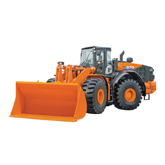
- Page 1 PART NO. ENMNHG-NA1-2 Operator's Manual Wheel Loader URL:http://www.hitachi-c-m.com Serial No. 005201 and up This book is printed on recycled paper. PRINTED IN JAPAN (T) 2018, 06...
- Page 2 INTRODUCTION Read this manual carefully to learn how to operate and Warranty is provided as a part of Hitachi’s support service your machine correctly. Failure to do so could program for customers who operate and maintain their result in personal injury or machine damage.
- Page 3 INDEX MACHINE NUMBERS SAFETY SAFETY LABELS COMPONENTS NAME OPERATOR’S STATION BREAK-IN OPERATING THE ENGINE MOVING THE MACHINE OPERATING THE MACHINE TRANSPORTING MAINTENANCE MAI N TENANCE UNDER SPECI A L ENVI R ONMENTAL CONDI T I O NS STORAGE TROUBLESHOOTING SPECIFICATIONS INDEX ENMNHG-NA1-2...
- Page 4 MEMO ............................................................................................................................................................................................................................................................................................................................................................................................................................................................................................................................................................................................................................................................................................................................................................................................................................................................................................................................................................................................................................................................................................................................................................................................................................................................................................................................................................................................................................................................................................
-
Page 5: Table Of Contents
CONTENTS MACHINE NUMBERS ............1 Prevent Fires ................... S-29 Evacuating in Case of Fire ............S-30 SAFETY ................S-1 Beware of Exhaust Fumes............S-31 Recognize Safety Information ............S-1 Precautions for Welding and Grinding ......... S-31 Understand Signal Words .............S-1 Avoid Heating Near Pressurized Fluid Lines ....... S-31 Follow Safety Instructions ............S-2 Avoid Applying Heat to Lines Containing Flammable Prepare for Emergencies ...............S-3... - Page 6 CONTENTS Work Light Indicator (Yellow) ........... 1-18 Work Light Switch ................ 1-87 Clearance Light Indicator (Green) .......... 1-19 Parking Brake Switch ..............1-88 Control Lever Lock Indicator (Red) ......... 1-19 Neutral Lever Lock (for the Forward/Reverse Lever) ..1-89 Multi Function Monitor .............. 1-20 Horn Switch ..................
- Page 7 CONTENTS Ash Tray ..................1-117 Rear Grille ..................1-150 Auto Air Conditioner ..............1-118 Steps....................1-151 Feature ..................1-118 Tool Box ..................1-151 Components Name ..............1-119 Vandal-Resistant Devices............1-152 Controller Part Name and Function .......1-120 BREAK-IN ............... 2-1 Cab Heater Operation ............1-122 Break-in Period for New Machine ..........2-1 Cooling Operation ..............1-123 Work Mode for Break-in ..............2-1 Defroster Operation .............1-124...
- Page 8 CONTENTS Avoid Operation with Loads on Only One Side ....5-17 Check Axle Oil Level ............... 7-34 Excavation ..................5-18 Change Axle Oil ............... 7-36 Loading Accumulated Soil........... 5-18 Replace Axle Oil Cooler Line Filter (Option) ....7-38 Digging and Loading Level Ground ......... 5-19 Clean Axle Oil Cooler Fins (Option) ........
- Page 9 CONTENTS Check Electrical Harnesses and Fuses ......7-86 Check Fuel Injector ...............7-119 Fuse Box A ................. 7-87 Check Turbocharger .............7-119 Fuse Box B .................. 7-87 Check and Adjust Engine Controller (ECM) ....7-119 I. Brake System ................7-88 Check and Clean EGR Valve ..........7-119 Check Right and Left Brake Interlocking Check and Clean EGR Cooler ..........7-119 Performance ................
- Page 10 CONTENTS MEMO ............................................................................................................................................................................................................................................................................................................................................................................................................................................................................................................................................................................................................................................................................................................................................................................................................................................................................................................................................................................................................................................................................................................................................................................................................................................................................................................................................................................................................................................................................................
-
Page 11: Machine Numbers
MACHINE NUMBERS The manufacturing Nos. explained in this group is the individual number (serial No.) given to each machine and hydraulic components. These numbers are requested when inquiring any information on the machine and/or components. Fill these serial Nos. in the blank spaces in this group to immediately make them available upon request. - Page 12 MACHINE NUMBERS Aftertreatment Device TYPE MFG. NO. 95Z7B-SCR4 TYPE MFG. NO. 95Z7B-SCR4...
-
Page 13: Safety
SAFETY Recognize Safety Information These are the SAFETY ALERT SYMBOLS. When you see these symbols on your machine or in this manual, be alert to the potential for personal injury. Follow recommended precautions and safe operating practices. SA-2644 Understand Signal Words ... -
Page 14: Follow Safety Instructions
Do not use attachments and/or optional parts or equipment not authorized by Hitachi. Carefully read and follow all instructions for use and safety in the operator's manual for the attachment. Failure to do so may deteriorate the safety, function, and/or service life of the machine. -
Page 15: Prepare For Emergencies
SAFETY Prepare for Emergencies Be prepared if a fire starts or if an accident occurs. Keep a first aid kit and fire extinguisher on hand. Thoroughly read and understand the label attached on the fire extinguisher to use it properly. ... -
Page 16: Protect Against Noise
SAFETY Protect Against Noise Prolonged exposure to loud noise can cause impairment or loss of hearing. Wear a suitable hearing protective device such as earmuffs or earplugs to protect against objectionable or uncomfortably loud noises. SA-434 Inspect Machine ... -
Page 17: General Precautions For Cab
SAFETY General Precautions for Cab Before entering the cab, thoroughly remove all dirt and / or oil from the soles of your work boots. If any controls such as a pedal is operated while with dirt and / or oil on the soles of the operator’s work boots the operator’s foot may slip off the pedal, possibly resulting in a personal accident. -
Page 18: Use Handrails And Steps
SAFETY Use Handrails and Steps Falling is one of the major causes of personal injury. When you get on and off the machine, always face the machine and maintain a three-point contact with the steps and handrails. Do not use any controls as handholds. ... -
Page 19: Ensure Safety Before Rising From Or Leaving Operator's Seat
SAFETY Ensure Safety Before Rising from or Leaving Operator’s Seat Before rising from the operator’s seat to open / close either side window or to adjust the seat position, be sure to first lower the front attachment to the ground and then move the control lever lock switch to the lock ( ) position. -
Page 20: Move And Operate Machine Safely
SAFETY Move and Operate Machine Safely Bystanders can be run over. Take extra care not to run over bystanders. Be advised that there may be blind spots with rear view camera. Confirm the location of bystanders before moving, swinging, or operating the machine by sight and mirrors as well as the rear view monitor. -
Page 21: Operate Only From Operator's Seat
SAFETY Operate Only from Operator’s Seat Inappropriate engine starting procedures may cause the machine to runaway, possibly resulting in serious injury or death. Start the engine only when seated in the operator's seat. NEVER start the engine while standing on the tire or on ground. -
Page 22: Investigate Job Site Beforehand
SAFETY Investigate Job Site Beforehand When working at the edge of an excavation or on a road shoulder, the machine could tip over, possibly resulting in serious injury or death. Investigate the configuration and ground conditions of the job site beforehand to prevent the machine from falling and to prevent the ground, stockpiles, or banks from collapsing. -
Page 23: Equipment Of Head Guard, Rops, Fops
SAFETY Equipment of Head Guard, ROPS, FOPS In case the machine is operated in areas where the possibility of falling stones or debris exist, equip a head guard, ROPS, or FOPS according to the potential hazardous conditions. (The standard cab for this machine corresponds to ROPS and FOPS.) Any modification of the ROPS structure will modify its performances and its certification will be lost. -
Page 24: Keep Riders Off Machine
SAFETY Keep Riders Off Machine Riders on machine are subject to injury such as being struck by foreign objects and being thrown off the machine. Only the operator should be on the machine. Keep riders off. Riders also obstruct the operator’s view, resulting in the machine being operated in an unsafe manner. -
Page 25: Drive Machine Safely (Work Site
SAFETY Drive Machine Safely (Work Site) Before driving the machine, always confirm that the steering wheel and/or joystick steering (option) and forward/reverse lever (switch) direction corresponds to the direction you wish to drive. Be sure to detour around any obstructions. ... -
Page 26: Drive Safely With Bucket Loaded
SAFETY Drive Safely with Bucket Loaded If the machine is operated incorrectly while driving with the bucket loaded, the machine may turn over. Be sure to follow all of the instructions indicated below. When driving the machine on a job site with the bucket loaded, hold the bucket as low as possible to keep the machine balanced and to have good visibility. -
Page 27: Travel On Public Roads Safely
SAFETY Travel on Public Roads Safely This machine is not allowed to drive on public roads with the bucket loaded. Be sure to empty the bucket. Hold the bucket at mark (A) 350 mm (14 in) above the road surface as illustrated. -
Page 28: Avoid Accidents From Backing Up And Turning
SAFETY Avoid Accidents from Backing Up and Turning Make sure no one is working under or close to the machine before backing up or turning the machine to avoid personal injury and / or death by being run over or entangled in the machine. -
Page 29: Avoid Positioning Bucket Or Attachment Over Anyone
SAFETY Avoid Positioning Bucket or Attachment Over Anyone Never allow the bucket or attachment to pass over co- workers and / or the dump truck operator’s cab. Falling material from the bucket or contact with bucket or attachment may cause serious personal accidents and / or damage to the machine. -
Page 30: Never Undercut A High Bank
SAFETY Never Undercut a High Bank The edges could collapse or a land slide could occur causing serious injury or death. SA-519 Dig with Caution Accidental severing of underground cables or gas lines may cause an explosion and / or fire, possibly resulting in serious injury or death. -
Page 31: Avoid Power Lines
SAFETY Avoid Power Lines Serious injury or death can result from contact with electric lines. Never move any part of the machine or load closer to any electric line than 3 m (10 ft) plus twice the line insulator length. SA-455 Precautions for Operation ... -
Page 32: Object Handling
SAFETY Object Handling CRANING OPERATION USING THE MACHINE IS NOT ALLOWED. If a lifted load should fall, any person nearby may be struck by the falling load or may be crushed underneath it, resulting in serious injury or death. Never attach a sling or chain to the bucket teeth or to the attachment (fork or grapple for example). -
Page 33: Park Machine Safely
SAFETY Park Machine Safely To avoid accidents: Park the machine on a firm, level surface. Lower bucket to the ground. Put the forward / reverse lever (switch) in neutral, and turn the parking brake switch (lever) ON (parking brake) position. -
Page 34: Transport Safely
SAFETY Transport Safely Be careful because the machine may turn over when loading or unloading the machine on or off of a truck or trailer. Observe the related regulations and rules for safe transportation. Less than 15 ° ... -
Page 35: Handle Fluids Safely−Avoid Fires
SAFETY Handle Fluids Safely−Avoid Fires Handle fuel with care; it is highly flammable. If fuel ignites, an explosion and / or a fire may occur, possibly resulting in serious injury or death. Do not refuel the machine while smoking or when near open flame or sparks. -
Page 36: Practice Safe Maintenance
SAFETY Practice Safe Maintenance To avoid accidents: Understand service procedures before starting work. Keep the work area clean and dry. Do not spray water or steam inside cab. Never lubricate or service the machine while it is moving. ... -
Page 37: Warn Others Of Service Work
SAFETY Sufficiently illuminate the work site. Use a maintenance work light when working under or inside the machine. Always use a work light protected with a guard. In case the light bulb is broken, spilled fuel, oil, antifreeze fluid, or window washer fluid may catch fire. -
Page 38: Stay Clear Of Moving Parts
SAFETY Stay Clear of Moving Parts Entanglement in moving parts can cause serious injury. To prevent accidents, care should be taken to ensure that hands, feet, clothing, jewelry and hair do not become entangled when working around rotating parts. SA-026 Support Maintenance Properly ... -
Page 39: Prevent Parts From Flying
SAFETY Prevent Parts from Flying Travel reduction gears are under pressure. As pieces may fly off, be sure to keep body and face away from AIR RELEASE PLUG to avoid injury. GEAR OIL is hot. Wait for GEAR OIL to cool, then gradually loosen AIR RELEASE PLUG to release pressure. -
Page 40: Replace Rubber Hoses Periodically
SAFETY Replace Rubber Hoses Periodically Rubber hoses that contain flammable fluids under pressure may break due to aging, fatigue, and abrasion. It is very difficult to gauge the extent of deterioration due to aging, fatigue, and abrasion of rubber hoses by inspection alone. -
Page 41: Prevent Fires
SAFETY Prevent Fires Check for Oil Leaks: Fuel, hydraulic oil and lubricant leaks can lead to fires. Check for oil leaks due to missing or loose clamps, kinked hoses, lines or hoses that rub against each other, damage to the oil-cooler, and loose oil-cooler flange bolts. -
Page 42: Evacuating In Case Of Fire
SAFETY Check Key Switch: If a fire breaks out, failure to stop the engine will escalate the fire, hampering fire fighting. Always check key switch function before operating the machine every day: 1. Start the engine and run it at low idle. 2. -
Page 43: Beware Of Exhaust Fumes
SAFETY Beware of Exhaust Fumes Prevent asphyxiation. Engine exhaust fumes can cause sickness or death. If you must operate in a building, be sure there is adequate ventilation. Either use an exhaust pipe extension to remove the exhaust fumes or open doors and windows to bring enough outside air into the area. -
Page 44: Avoid Applying Heat To Lines Containing Flammable Fluids
SAFETY Avoid Applying Heat to Lines Containing Flammable Fluids Do not weld or flame cut pipes or tubes that contain flammable fluids. Clean them thoroughly with nonflammable solvent before welding or flame cutting them. Precautions for Handling Accumulator and Gas Damper High-pressure nitrogen gas is sealed in the accumulator and the gas damper. -
Page 45: Remove Paint Before Welding Or Heating
Keep bystanders out of the work site during operation. Asbestos might be present in imitation parts. Use only genuine Hitachi Parts. S-33... -
Page 46: Prevent Battery Explosions
SAFETY Prevent Battery Explosions Battery gas can explode. Keep sparks, lighted matches, and flame away from the top of battery. Never check battery charge by placing a metal object across the posts. Use a voltmeter or hydrometer. ... -
Page 47: Handle Chemical Products Safely
Improperly disposing of waste can threaten the environment and ecology. Potentially harmful waste used with Hitachi equipment includes such items as oil, fuel, coolant, brake fluid, filters, DEF, and batteries. Use leakproof containers when draining fluids. Do not use food or beverage containers that may mislead someone into drinking from them. -
Page 48: Notes For Aftertreatment Device
SAFETY Notes for Aftertreatment Device Urea SCR System The aftertreatment device removes particulate matter (PM) and nitrogen oxide (NOx) from the exhaust gas. Follow the instructions below to prevent the aftertreatment device from being damaged. WARNING: Exhaust gas from the aftertreatment device, muffler, exhaust piping and tail piping becomes hot during and just after engine running and regeneration of aftertreatment device. -
Page 49: Precaution For Communication Terminal Equipment (Option
SAFETY Precaution for Communication Terminal Equipment (Option) This machine may have a communication terminal equipment emitting electrical waves installed in the right rear corner within the cab. There is a possibility that a medical device, including an implantable device such as a cardiac pacemaker, would be affected and would malfunction by the electrical waves emitted from the communication terminal equipment. -
Page 50: Articulation Stopper (Lock Bar
SAFETY Articulation Stopper (Lock Bar) WARNING: With articulation stopper in LOCKED position, machine will not steer; which, while operating, could cause an accident, injury or death. Do not lock Articulation Stopper during normal operation. Articulation stopper locks the front and rear chassis to prevent them from sudden articulation during inspection or transportation. -
Page 51: Joystick Steering System On/Off (Option
SAFETY Joystick Steering System ON/OFF (Option) WARNING: Accidental movement of the stick while "Raised" position getting on or off the machine may cause unexpected movement of the machine resulting in an accident, injury, or death. Always stop, and properly park the machine and turn off the joystick steering system while getting on or off the machine. -
Page 52: Safety Labels
SAFETY LABELS All safety signs and their locations on the machine are illustrated in this group. Become familiar with the contents of the safety labels by reviewing them on the machine and understanding them, to ensure safe machine operation. Always keep the safety labels clean. In case a safety sign is lost or no longer readable, immediately-obtain a new replacement and affix it again in position on the machine. - Page 53 SAFETY LABELS 95Z7B-S-40 S-41...
- Page 54 SAFETY LABELS 1. Bucket and Hood CAUTION: Sign indicates a fall hazard. Do not step on or stand in this area. 44787-24370 95Z7B-S-41-1 2. Accumulator residual pressure WARNING: Oil injection hazard. Nitrogen accumulator contains compressed gas and fluid which could result in death or serious injury.
- Page 55 SAFETY LABELS 3. Front Top of Engine Room WARNING: Burn Hazard Avoid skin contact with highly heated parts such as the engine, muffler, etc. immediately after operation of the machine. Severe burns may result. 44787-24990 95Z7B-S-42-2 4. Use no starting fluid WARNING: Explosion Hazard ...
- Page 56 SAFETY LABELS 5. Top of Hydraulic Oil Tank 44787-25030 WARNING: Burn Hazard Sign indicates a burn hazard from the pressurized tank spurting hot oil if the oil inlet is uncapped during or right 95Z7B-S-43-1 after operation. Read manual for safe and proper handing. 6.
- Page 57 SAFETY LABELS 7. Side of Engine Starter 44787-24930 DANGER: Runover Hazard If the engine is not started correctly the machine may suddenly start to move. Start the engine from the operator's seat only. 95Z7B-S-44-1 8. Both Sides of Front Chassis DANGER: Crush Hazard ...
- Page 58 SAFETY LABELS 10. Both Sides of Counterweight WARNING: Runover Hazard Avoid injury or fatality from being run over with the machine. Keep everyone away from the machine when operating. 95Z7B-S-45-1 44787-24400 11. Bottoms at Both Right and Left Side Covers of Rear Chassis WARNING: Entanglement Hazard ...
- Page 59 SAFETY LABELS 13. Inside Battery Box CAUTION: Shock Hazard Sign indicates a possible shock hazard from handling battery terminals. Read manual for safe and proper handling. 44787-24350 95Z7B-S-46-1 14. Inside Battery Box WARNING: Explosion Hazard Sign indicates an explosion hazard. Keep fire and open flames away from this area.
- Page 60 SAFETY LABELS 16. Top of Battery Recycle Batteries Batteries contain lead and acid. Obey all local and federal laws and regulation on disposal of batteries and electrolyte solution. 44774-23030 95Z7B-S-47-1 17. Top of Battery label 44787-25010 DANGER: Explosion Hazard ...
- Page 61 SAFETY LABELS 19. Cab Inside Right Front Column (First safety sign from the top) WARNING Prior to operation, maintenance, disassembling, and transportation of the machine, be sure to read and understand the Operator's Manual. 90Z7-S-48B1 44787-24940 20. Cab Inside Right Front Column (2nd safety sign from the top) DANGER: Electrocution Hazard...
- Page 62 SAFETY LABELS 22. Cab Inside Right Front Column (4th safety sign from the top) WARNING: Rollover Hazard To minimize the injury due to an overturning accident, be sure to fasten the seat belt prior to operating the machine. 90Z7-S-49B 44787-24970 23.
- Page 63 SAFETY LABELS 25. Both Right and Left Side of Engine Housing Frame WARNING: Entanglement Hazard Sign indicates a hazard of rotating parts, such as fan. Turn off before inspection and maintenance. 44787-24380 95Z7B-S-50-1 26. DEF Tank IMPORTANT: Avoid Contamination ...
- Page 64 SAFETY LABELS 28. Radiator Cap Cover (Coolant Replacement Instruction) 95Z7B-S-43-2 44787-25890 29. Cab Right Outside (Option) label 44787-25020 95Z7B-S-52-1 S-52...
-
Page 65: Components Name
COMPONENTS NAME Components Name 1- Cutting Edge (BOC) 2- Bucket 3- Bell Crank (Lever) 4- Bucket Cylinder 5- Front Combination Light (Headlight/Turn Signal/Clearance Light/Hazard Light) 6- Outside Rear View Mirror 7- Front Work Light 8- ROPS Cab 9- Rear Fender 10- Front Fender 95Z7B-1-1-1 11- Lift Arm (Boom) Cylinder... - Page 66 COMPONENTS NAME 95Z7B-1-2-1 1- Bolt on Cutting Edge 17- Transmission 2- Bucket 18- Second (Front and Center) Propeller Shaft 3- Bucket Cylinder Rod Pin 19- Steering Cylinder 4- Bucket Cylinder 20- Front Axle 5- Front Combination Lamp 21- Lift Arm (Boom) Cylinder 6- Hydraulic Oil Tank 22- Lift Arm (Boom) Cylinder Rod Pin 7- Air Cleaner...
-
Page 67: Operator's Station
OPERATOR'S STATION Aftertreatment Device The machine is equipped with the aftertreatment system combining Diesel Oxidation Catalyst (DOC) block (1) with Selective Catalytic Reduction (SCR) block (2) to remove nitrogen oxide (NOx) from the exhaust gas in order to meet governmental emissions regulations. The DOC reduces harmful substances in exhaust gas by chemical reaction, then DEF is injected in dosing module (injection chamber) (3) and mixed into the exhaust stream. - Page 68 OPERATOR'S STATION Refill DEF which meets JIS or ISO (International Organization for Standardization). If improper liquid (diesel oil, kerosene or gasoline) is refilled in the DEF tank, fire or system failure may result. Use only recommended engine oil. Using engine oil other than the recommended may result in malfunction of the aftertreatment device.
-
Page 69: Automatic Regeneration
OPERATOR'S STATION Automatic Regeneration White deposition may accumulate inside the aftertreatment device. An automatic regeneration (Auto-regeneration) mode is designed to automatically clean the aftertreatment device at regular intervals. The auto-regeneration may start during operation of the machine; you can continue to operate the machine. -
Page 70: Repeated Inhibiting Of Aftertreatment Device Cleaning
OPERATOR'S STATION Repeated Inhibiting of Aftertreatment Device Cleaning IMPORTANT: When the machine is operated without performing manual regeneration, the aftertreatment device may be damaged. Immediately move the machine to a safe area and perform manual regeneration. If auto-regeneration is inhibited or interrupted, the following auto-regeneration will be accompanied by the aftertreatment device manual regeneration request. -
Page 71: Cab Features
OPERATOR'S STATION Cab Features 1- Front Defroster 2- Front Console 3- Operator's Seat 4- Right Console 5- Document Holder 6- Hot/Cool Box 7- Rear Defroster 8- Glove Compartment 9- Cup Holder 10- Floor Mat MNEC-01-035... -
Page 72: Front Console
OPERATOR'S STATION Front Console 1- Air Conditioner Front Vent 2- Hazard Switch 3- Work Light Switch 4- Parking Brake Switch 5- Neutral Lever Lock (Forward/Reverse Lever) 6- Steering Wheel 7- Monitor Panel 8- Horn Switch MNEC-01-036 9- Accelerator Pedal 10- Brake Pedal 11- Front/Rear Window Wiper Switch 12- Forward/Reverse Lever/ Shift Switch 13- Steering Column Tilt Pedal... -
Page 73: Joystick Steering (Option)
OPERATOR'S STATION Joystick Steering (Option) There are two types of joystick steering. 21- Forward/Reverse Switch 22- Joystick 23- Shift Up Switch (without steering wheel) Quick Power Switch (with steering wheel) 24- Shift Down Switch (without steering wheel) Down Shift Switch (DSS) (with steering wheel) 25- Hold Switch (Under the Joystick) 26- Horn Switch (Under the Joystick) 95Z7-1-10-3... -
Page 74: Right Console
OPERATOR'S STATION Right Console Fingertip Control Type 1- Auxiliary Control Lever (Option) 2- Bucket Control Lever 3- Lift Arm Control Lever 4- Forward/Reverse Switch 5- Control Lever Lock Switch 6- Declutch Position Switch 7- Travel Mode Selector 8- Power Mode Selector MNEC-01-041 9- Forward/Reverse Selector Switch 10- Fan Reverse Rotation Switch... -
Page 75: Multi-Function Joystick Type
OPERATOR'S STATION Right Console Multi-Function Joystick Type 1- Forward/Reverse Switch 2- Multi-Function Joystick Lever 3- Quick Power Switch 4- DSS (Down Shift Switch) 5- Auxiliary Control Lever (Option) 6- Control Lever Lock Switch 7- Declutch Position Switch 8- Travel Mode Selector Switch MNEC-01-043 9- Power Mode Selector Switch 10- Forward/Reverse Selector Switch... -
Page 76: Monitor Panel
OPERATOR'S STATION Monitor Panel MNEC-01-001 1- Left Turn Signal Indicator 12- Discharge Warning Indicator 2- High Beam Indicator 13- Fuel Gauge 3- Work Light Indicator 14- Multi Function Monitor 4- Right Turn Signal Indicator 15- Communication System Error Indicator 5- Parking Brake Indicator 16- Coolant Temperature Gauge 6- Brake Oil Low Pressure Indicator 17- Overheat Indicator... -
Page 77: Parking Brake Indicator (Red)
OPERATOR'S STATION Parking Brake Indicator (Red) The parking brake indicator will light when the parking brake is applied. If the forward/reverse lever is moved to either the forward (F) or the reverse (R) position when the parking brake is applied, the alarm buzzer will sound. -
Page 78: Low Steering Oil Pressure Indicator (Option) (Red)
OPERATOR'S STATION Low Steering Oil Pressure Indicator (Option) (Red) IMPORTANT: The secondary steering system shall only be used temporarily when the steering oil pressure has dropped. If continuously used, it may damage the system. If the steering oil pressure decreases, the low steering oil pressure indicator and the service indicator will light, and the alarm buzzer will sound. -
Page 79: Engine Warning Indicator (Red)
OPERATOR'S STATION Engine Warning Indicator (Red) If any serious abnormality occurs in the engine and/or engine related parts, the red indicator will light. If the engine warning indicator and the service indicator light, immediately move the machine to a safe area, set the machine in the park position and stop the engine. -
Page 80: Air Filter Restriction Indicator (Red)
OPERATOR'S STATION Air Filter Restriction Indicator (Red) If the air cleaner element becomes clogged,, the air filter restriction indicator and the service indicator light. Immediately stop the engine and inspect the air cleaner element. Replace the element, if necessary. NOTE: This indicator may unexpectedly light when the coolant temperature gauge indicates the center or lower position. -
Page 81: Coolant Temperature Gauge
OPERATOR'S STATION Coolant Temperature Gauge The engine coolant temperature is indicated with a needle. When the needle stays in the range (1) during operation, the coolant temperature is normal. If the engine coolant temperature becomes abnormally high, the service indicator will flash and the alarm buzzer will sound. Stop machine operation and run the engine at low idle to lower the coolant temperature. -
Page 82: Turn Signal Indicator (Green)
OPERATOR'S STATION Turn Signal Indicator (Green) When the turn signal lever is operated, the turn signal and the turn signal indicator start flashing. M4GB-01-032 High Beam Indicator (Blue) When the head lights are used at the high beam position, the indicator will light. -
Page 83: Clearance Light Indicator (Green)
OPERATOR'S STATION Clearance Light Indicator (Green) When the clearance lights are turned ON, this indicator will light. M4GB-01-035 Control Lever Lock Indicator (Red) When the control lever lock switch is in ON position, the control lever lock indicator will light. MNEC-01-004 1-19... -
Page 84: Multi Function Monitor
OPERATOR'S STATION Multi Function Monitor Feature The multi function monitor displays various meters, indicators, operation mode selection and maintenance screen. Screen Configuration The multi function monitor consists of the following screens. There are 7 menus, and a further 13 sub menus. Basic Screen Main Menu Alarm List... -
Page 85: Default Setting
OPERATOR'S STATION Default Setting Function Item Default Auto Shut-Down ON/OFF of auto idling-stop function Time period for auto idling-stop activation 5 min Rear View Camera Monitor ON (Constant display) OFF (No display) AUTO AUTO (Display at reverse operation only) Aftertreatment Device Regeneration Inhibit regeneration Inhibited Shift Change Delay Mode... -
Page 86: Basic Screen
OPERATOR'S STATION Basic Screen 1- Engine Tachometer 2- Economy (ECO) Indicator 3- Speedometer 4- Transmission Oil Temperature Gauge 5- DEF Level Gauge 6- Air Conditioner Display MNHG-01-100EN 7- Ride Control Indicator (Option) 8- Seat Belt Indicator 9- Forward/Reverse Selector Switch Indicator 10- Declutch Indicator 11- Aftertreatment Device Indicator 12- Power Mode Indicator... -
Page 87: How To Use Screens
OPERATOR'S STATION How to Use Screens Displaying Basic Screen IMPORTANT: Start the engine after the basic screen is displayed. When the key switch is turned to the ON position, the starting screen displays for about two seconds and the basic screen displays. - Page 88 OPERATOR'S STATION Engine Tachometer (1) Engine tachometer (1) indicates the speed of currently running engine in a gauge form. (200 min step or "RPM") If the engine overspeeds, the color of the gauge changes. ECO Indicator (2) ECO indicator (2) lights when the engine runs in energy efficient condition.
- Page 89 OPERATOR'S STATION Forward/Reverse Selector Switch Indicator (9) The forward/reverse indicator lights when the forward/ reverse switch on the right console or on the multi-function lever is usable. NOTE: When the optional joystick steering is used, this indicator lights when the joystick steering system switch is turned on.
- Page 90 OPERATOR'S STATION Fan Reverse Rotation Indicator (16) Displays rotating direction of the fan. Normal Rotation The icon is not displayed. Changing Rotational The icon blinks. Direction Reverse Rotation The icon lights ON. HOLD Display (17) Hold display (17) is displayed when the hold switch on the side console is in ON position.
-
Page 91: Monitor Operation
OPERATOR'S STATION Monitor Operation Select/Confirm Knob (1) Push Push this switch while the basic screen is displayed, the Main Menu Screen opens. Push this switch after the menu screen, the action is confirmed. Rotate : Cursor moves. MNEC-01-006 Multi Function Monitor/Air Conditioner Switch Panel MNEC-01-078 ... -
Page 92: Alarm Occurrence Screen
OPERATOR'S STATION Alarm Occurrence Screen In case any abnormality occurs, alarm symbols (1) and service indicator (3) are displayed on the basic screen. MNHG-01-290EN Basic Screen If 8 or more alarms are generated, the alarm symbols (1) can be scrolled by rotating selector knob (2). When the rear view monitor is operating, service indicator (3) is displayed. - Page 93 OPERATOR'S STATION Follow the procedure below to display detailed information for an alarm. Push selector knob (1) on the basic screen to display the main menu. MNHG-01-290EN Rotate selector knob (1) to select the alarm list, and push selector knob (1). MNEC-01-006 NOTE: The main menu displays the alarm list (faults) only when an alarm occurs.
-
Page 94: Remedy
OPERATOR'S STATION Remedy Display Contents of Alarms Remedy System Failure Alarm Communication system is abnormal. Consult your nearest authorized dealer. Brake Oil Pressure Alarm Brake oil pressure has decreased. Immediately stop the machine and check the brake system. Low Steering Oil Pressure Steering oil pressure has decreased. - Page 95 OPERATOR'S STATION Display Contents of Alarms Remedy Hydraulic Oil Overheat Alarm Hydraulic oil temperature is above normal. Stop operation. Run the engine at slow idle speed to lower the oil temperature. Axle Oil Temperature Alarm Axle oil temperature is above normal. Check if the service brake drags. Transmission Oil Temperature Transmission oil temperature is above normal.
- Page 96 OPERATOR'S STATION Display Contents of Alarms Remedy Exhaust Temperature Rise Exhaust temperature is abnormally high. Alarm Stop machine operation, apply parking brake, and check the exhaust lines. Intake Air Temperature Rise Intake air temperature is abnormally high. Stop machine operation Alarm and apply parking brake.
-
Page 97: Def/Scr System Alarm
OPERATOR'S STATION DEF/SCR System Alarm When the DEF level becomes low and/or the Urea SCR system malfunctions, the engine performance is controlled depending on the status. The operator is alerted with alarm indicators. Move and park the machine in a safe place and follow the displayed message, or troubleshooting guide for the accompanied alarms. -
Page 98: Urea Scr System Malfunction
OPERATOR'S STATION Urea SCR System Malfunction Alarm Indicator Status/Inducement Urea SCR system is broken. (Red, light) Urea SCR system is broken. Engine output is restricted. (Red, slow blink) Urea SCR system is broken. Engine output and speed are restricted. (Red, fast blink) Contact your authorized dealer for service. -
Page 99: Aftertreatment Device Regeneration
OPERATOR'S STATION Aftertreatment Device Regeneration To keep the system working correctly, periodically, the collected deposit is removed by purging it at a high temperature. This process is known as "regeneration". The regeneration is done in three ways; automatic regeneration (abbreviated as auto-regeneration), manual regeneration, and service regeneration. -
Page 100: Automatic Regeneration (Auto-Regeneration)
OPERATOR'S STATION Automatic regeneration (Auto-regeneration) The machine automatically increases the exhaust temperature during normal operation to purge the deposit. There are no actions on the part of the operator when auto-regeneration is performed. Auto-regeneration may start while operating the machine, and there is no need to stop the machine when this happens. -
Page 101: Manual Regeneration
OPERATOR'S STATION Manual Regeneration When the deposit level increases to a level that is more than an auto-regeneration can remove, a manual regeneration is required. The yellow regeneration symbol (shown below)(1) and service indicator (2) appear to make the operator aware that this is required. -
Page 102: Main Menu
OPERATOR'S STATION Main Menu IMPORTANT: If the forward/reverse lever is in the forward or reverse position, the basic screen is displayed. (You can not change to the other screen.) When the forward/reverse lever is changed to forward or reverse position while displaying the main menu screen, the screen changes back to the basic screen. -
Page 103: Ride Control Drive Speed Setting (Option)
OPERATOR'S STATION Ride Control Drive Speed Setting (Option) 1. Press selector knob (2) while displaying basic screen (1) to display Main Menu screen (3). MNHG-01-103EN MNEC-01-006 2. Rotate selector knob (2) to highlight Ride Control (4). 3. Press selector knob (2) to display Ride Control Drive Speed Setting screen (5). -
Page 104: Dual Lift Arm Auto-Leveler
OPERATOR'S STATION Dual Lift Arm Auto-Leveler 1. Press selector knob (2) while displaying basic screen (1) to display Main Menu screen (3). MNHG-01-103EN MNEC-01-006 2. Rotate selector knob (2) to highlight Dual Lift Arm Auto- Leveler (4). MNHG-01-110EN 3. Press selector knob (2) to display Dual Lift Arm Auto- Leveler screen (5). -
Page 105: Height/Lower Kickout On/Off, Stop Height Setting
OPERATOR'S STATION Height/Lower Kickout ON/OFF, Stop Height Setting Rotate selector knob (2) to highlight ON (8). ON/OFF Selection Press selector knob (2) to turn ON (enabled). (A box next to ON turns green.) This enables the setting of the lift arm height. Press selector knob (2) again to turn OFF (disabled). -
Page 106: Brightness Adjustment
OPERATOR'S STATION Brightness Adjustment 1. Press selector knob (2) while displaying Basic Screen (1) to display Main Menu screen (3). MNHG-01-103EN 2. Rotate selector knob (2) to highlight Brightness MNEC-01-006 Adjustment (4). MNHG-01-120EN 1-42... - Page 107 OPERATOR'S STATION 3. Press selector knob (2) to display Brightness Adjustment screen (5). MNEC-01-006 4. Rotate selector knob (2) clockwise to make the screen brighter, counterclockwise to make the screen darker. NOTE: When the machine's head light switch is turned ON, the monitor screen changes to night mode and mark (6) is MNHG-01-121EN displayed.
-
Page 108: Mail (Option)
OPERATOR'S STATION Mail (Option) IMPORTANT: This function is available only to a machine equipped with a communication terminal. When using the mail function, consult your nearest authorized dealer. 1. Press selector knob (2) while displaying Basic Screen (1) to display Main Menu screen (3). MNHG-01-103EN MNEC-01-006 2. - Page 109 OPERATOR'S STATION 6. While mail information is sent to the communication terminal, the message "Wait." is displayed on the screen. MNHG-01-132EN 7. When the communication terminal completes receiving mail information, the message "Request Was Accepted." is displayed on the screen. Push back key (6) to return to the Mail screen.
-
Page 110: Setting Menu
OPERATOR'S STATION Setting Menu Setting menu consists of date and time setting, auto idling stop setting, and rear view camera monitor setting. 1. Press selector knob (2) while displaying basic screen (1) to display Main Menu screen (3). MNHG-01-103EN MNEC-01-006 2. -
Page 111: Date And Time
OPERATOR'S STATION Date and Time Time, date and display mode can be set on this screen. Year- month-day format and 24h/12h display mode are selected in the display setting. Time Adjustment 1. Press selector knob (2) while displaying Basic Screen (1) to display Main Menu screen (3). - Page 112 OPERATOR'S STATION 5. Press selector knob (2) to display Date and Time screen (7). MNEC-01-006 6. Rotate selector knob (2) to highlight Time Setting (8). 7. Press selector knob (2) to display Time Setting screen (9). 8. Rotate selector knob (2) to highlight Hour or Minute and push selector knob (2).
-
Page 113: Date Adjustment
OPERATOR'S STATION Date Adjustment 1. Press selector knob (2) while displaying Basic Screen (1) to display Main Menu screen (3). MNHG-01-103EN MNEC-01-006 2. Rotate selector knob (2) to highlight Setting Menu (4). MNHG-01-140EN 3. Press selector knob (2) to display Setting Menu screen (5). - Page 114 OPERATOR'S STATION 5. Press selector knob (2) to display Date and Time screen (7). MNEC-01-006 6. Rotate selector knob (2) to highlight Date Setting (8). 7. Press selector knob (2) to display Date Setting screen (9). 8. Rotate selector knob (2) to highlight Year, Month or Day and push selector knob (2).
-
Page 115: Display Mode Setting
OPERATOR'S STATION Display Mode Setting 1. Press selector knob (2) while displaying Basic Screen (1) to display Main Menu screen (3). MNHG-01-103EN MNEC-01-006 2. Rotate selector knob (2) to highlight Setting Menu (4). MNHG-01-140EN 3. Press selector knob (2) to display Setting Menu screen (5). - Page 116 OPERATOR'S STATION 5. Press selector knob (2) to display Date and Time screen (7). MNEC-01-006 6. Rotate selector knob (2) to highlight Display Form (8). MNHG-01-148EN 7. Press selector knob (2) to display Display Form screen (9). 8. Rotate selector knob (2) to highlight Date (10) and push selector knob (2).
-
Page 117: Auto Idling Stop
OPERATOR'S STATION Auto Idling Stop WARNING: This function automatically idles, then stops the engine. Take extra care on the work and environment when using this function. The auto idling stop function can be set in this screen. Set the auto idling stop time and enable the function beforehand (set to ON). -
Page 118: Acting Time Setting
OPERATOR'S STATION 5. Press selector knob (2) to display Auto Shut-Down screen (7). MNEC-01-006 6. Rotate selector knob (2) to highlight ON (8). 7. Press selector knob (2) to set the auto shut-down function ON and indicator (11) will be lit. Press selector knob (2) again to set the auto shut-down function OFF and indicator (11) goes off. -
Page 119: Rear View Camera Monitor
OPERATOR'S STATION Rear View Camera Monitor IMPORTANT: The image displayed on the rear view monitor is meant only as an aid. Actual position and distance of people and objects in the rear view monitor will be different from the actual view. When operating the machine, pay thorough attention to the surroundings with use of mirrors and windows. - Page 120 OPERATOR'S STATION 5. Press selector knob (2) to display Rear View Camera Monitor screen (7). MNEC-01-006 6. Press selector knob (2) to turn the rear view camera monitor ON/OFF/AUTO. 7. When the rear view camera monitor is ON, rear view image is continuously displayed on the basic screen.
-
Page 121: Aftertreatment Device Regeneration Inhibited
OPERATOR'S STATION Aftertreatment Device Regeneration Inhibited IMPORTANT: The aftertreatment device regeneration can be inhibited at this screen to prevent auto regeneration while operating the machine in a flammable area or indoors. Setting Procedure MNHG-01-103EN 1. Press selector knob (2) while displaying Basic Screen (1) to display Main Menu screen (3). - Page 122 OPERATOR'S STATION 4. Rotate selector knob (2) to highlight Aftertreatment Device Regeneration Inhibited (6). MNEC-01-006 5. Press selector knob (2) to display Aftertreatment Device Regeneration Inhibited screen (7). 6. Rotate selector knob (2) to highlight (8), and press MNHG-01-170EN selector knob (2) to display Aftertreatment Device Regeneration Inhibited screen (9).
-
Page 123: Transmission Setting
OPERATOR'S STATION Transmission Setting Shift Change Delay Mode Setting Refer to page 4-6 for Shift Change Delay Mode. 1. Press selector knob (2) while displaying Basic Screen (1) to display Main Menu screen (3). MNHG-01-103EN MNEC-01-006 2. Rotate selector knob (2) to highlight Setting Menu (4). MNHG-01-140EN 3. - Page 124 OPERATOR'S STATION 4. Rotate selector knob (2) to highlight Transmission Setting Menu (6). MNHG-01-180EN 5. Press selector knob (2) to display Transmission Setting screen (7). 6. Rotate selector knob (2) to highlight Shift Change Delay Mode (8). MNHG-01-181EN 7. Press selector knob (2) to display Shift Change Delay Mode screen (9).
-
Page 125: Lockup Setting
OPERATOR'S STATION Lockup Setting Lock-up clutch is provided for efficient power transmission from the engine, that helps to improve fuel efficiency and have higher ground speed. Use this setting to activate the lockup shifting (refer to page 4-5). NOTE: The lock-up control directly links the transmission to the engine when the Auto Shift Mode 1 or 2 is selected. - Page 126 OPERATOR'S STATION 4. Rotate selector knob (2) to highlight Transmission Setting Menu (6). MNHG-01-180EN 5. Press selector knob (2) to display Transmission Setting screen (7). 6. Rotate selector knob (2) to highlight Lockup (8). MNHG-01-184EN 7. Press selector knob (2) to display Lockup setting screen (9).
-
Page 127: Traction Control Setting
OPERATOR'S STATION Traction Control Setting If the tire is ready to spin, by keeping the traction control function ON, the engine speed is temporarily slowed down and tire spin is reduced. This increases tire life. 1. Press selector knob (2) while displaying Basic Screen (1) to display Main Menu screen (3). - Page 128 OPERATOR'S STATION 4. Rotate selector knob (2) to highlight Transmission Setting Menu (6). MNEK-01-180EN 5. Press selector knob (2) to display Transmission Setting screen (7). 6. Rotate selector knob (2) to highlight Traction Control (8). 95Z7-01-05 7. Press selector knob (2) to display Traction Control screen (9).
-
Page 129: Parallel/Tandem Switching Height Setting
OPERATOR'S STATION Parallel/Tandem Switching Height Setting With parallel/tandem circuits, the boom and bucket can be operated at the same time, under a set height. This setting is adjustable. 1. Press selector knob (2) while displaying basic screen (1) MNHG-01-103EN to display main menu screen (3). MNEC-01-006 2. - Page 130 OPERATOR'S STATION 4. Rotate selector knob (2) to highlight Parallel/Tandem Switching Height (6). MNEC-01-006 5. Press selector knob (2) to display Parallel/Tandem Switching Height screen (7). 6. When the lift arm height changes by operating the lift MNHG-01-190EN arm control lever, the height is displayed on segment (8). 7.
-
Page 131: Warm Up Operation
OPERATOR'S STATION Warm Up Operation Refer to "Cold Weather Warm Up" (page 3-13) for the operation when using this setting. 1. Press selector knob (2) while displaying basic screen (1) to display main menu screen (3). MNHG-01-103EN MNEC-01-006 2. Rotate selector knob (2) to highlight Setting Menu (4). MNHG-01-140EN 3. - Page 132 OPERATOR'S STATION 4. Rotate selector knob (2) to highlight Warm Up (6). MNEC-01-006 5. Press selector knob (2) to display Warm Up Setting screen (7). 6. Press selector knob (2) to turn ON (enabled). MNHG-01-200EN Press selector knob (2) again to turn OFF (disabled). NOTE: When the function is ON, the mark ""...
-
Page 133: Display Item Selection
OPERATOR'S STATION Display Item Selection Unit system displayed on the monitor can be selected in this screen. 1. Press selector knob (2) while displaying basic screen (1) MNHG-01-103EN to display main menu screen (3). MNEC-01-006 2. Rotate selector knob (2) to highlight Setting Menu (4). MNHG-01-140EN 3. - Page 134 OPERATOR'S STATION 5. Press selector knob (2) to display Display Item Selection screen (7). MNEC-01-006 6. Rotate selector knob (2) to highlight Unit. Press selector knob (2) to set the unit (Metric or US system). 7. Rotate selector knob (2) to highlight Accumulated Operation Display.
-
Page 135: Main Menu Display Order Change
OPERATOR'S STATION Main Menu Display Order Change Menu sequence of "Ride Control" (option), "Dual Lift Arm Auto Leveler", "Brightness Adjustment" and "Mail" can be changed in this screen. Frequently used menu can be located on top of the screen. 1. Press selector knob (2) while displaying Basic Screen (1) MNHG-01-103EN to display Main Menu screen (3). - Page 136 OPERATOR'S STATION 3. Press selector knob (2) to display Setting Menu screen (5). 4. Rotate selector knob (2) to highlight Main Menu Sequence Change (6). MNHG-01-230EN-KC 5. Press selector knob (2) to display Main Menu Sequence MNEC-01-006 Change screen (7). 6.
-
Page 137: Information Menu
OPERATOR'S STATION Information Menu The information menu includes Operation, Maintenance, Troubleshooting and Monitoring. 1. Press selector knob (2) while displaying Basic Screen (1) to display Main Menu screen (3). MNHG-01-103EN MNEC-01-006 2. Rotate selector knob (2) to highlight Information Menu (4). -
Page 138: Operation Condition
OPERATOR'S STATION Operation Condition The Operation screen displays fuel consumption, operating hours, and fuel consumption rate from resetting of the monitoring unit. Fuel Consumption MNHG-01-103EN 1. Press selector knob (2) while displaying Basic Screen (1) to display Main Menu screen (3). MNEC-01-006 2. - Page 139 OPERATOR'S STATION 5. Press selector knob (2) to display Operation screen (7). 6. Rotate selector knob (2) to highlight Fuel Consumption MNEC-01-006 (8) or Machine Information (9). 7. Press selector knob (2) while selecting Fuel Consumption MNHG-01-242EN (8) to display Fuel Consumption screen (10). The Machine Operation Hours, Fuel Consumption, and Average Fuel Consumption Rate can be checked on Fuel Consumption screen (10).
-
Page 140: Maintenance
OPERATOR'S STATION Maintenance The maintenance screen includes maintenance notice, remaining hours until the next maintenance, and maintenance intervals. Maintenance Items Engine Oil Engine Oil Filter MNHG-01-103EN Hydraulic Oil Hydraulic Oil Pilot Filter Hydraulic Oil Return Filter ... - Page 141 OPERATOR'S STATION 5. Press selector knob (2) to display Maintenance screen (7). 6. Rotate selector knob (2) to highlight Maintenance Notice MNEC-01-006 (8). 7. Press selector knob (2) to turn the Maintenance Notice ON. Press selector knob (2) again to turn the Maintenance Notice OFF.
-
Page 142: Time Remains And Maintenance Interval
OPERATOR'S STATION Time Remains and Maintenance Interval 1. Press selector knob (2) while displaying Basic Screen (1) to display Main Menu screen (3). MNHG-01-103EN MNEC-01-006 2. Rotate selector knob (2) to highlight Information Menu (4). MNHG-01-240EN 3. Press selector knob (2) to display Information Menu screen (5). - Page 143 OPERATOR'S STATION 5. Press selector knob (2) to display Maintenance screen (7). 6. Rotate selector knob (2) to highlight a maintenance item to be checked (8). (In the right example, Engine Oil is MNEC-01-006 selected.) 7. Press selector knob (2) to display the time remaining for the selected maintenance item.
-
Page 144: Troubleshooting
OPERATOR'S STATION Troubleshooting An active fault code generated by the controller connected to the controller area network is displayed on this screen. 1. Press selector knob (2) while displaying Basic Screen (1) to display Main Menu screen (3). MNHG-01-103EN MNEC-01-006 2. - Page 145 OPERATOR'S STATION 4. Rotate selector knob (2) to highlight Troubleshooting (6). MNHG-01-260EN-KC 95MNEC-01-261EN 5. Press selector knob (2) to start troubleshooting. After displaying "Wait." message, the screen displays controller troubleshooting (7). 6. Active fault codes are displayed at the right side of each 95MNEC-01-262EN item.
-
Page 146: Monitoring
OPERATOR'S STATION Monitoring 1. Press selector knob (2) while displaying Basic Screen (1) to display Main Menu screen (3). MNHG-01-103EN MNEC-01-006 2. Rotate selector knob (2) to highlight Information Menu (4). MNHG-01-240EN 3. Press selector knob (2) to display Information Menu screen (5). - Page 147 OPERATOR'S STATION 5. Press selector knob (2) to display Monitoring screen (7). NOTE: When the "PM Accumulation" bar reaches the right end, auto-regeneration takes place. However, auto- regeneration may not be performed depending on the machine condition. The PM Accumulation is not displayed during regeneration. MNHG-01-271EN 1-83...
- Page 148 OPERATOR'S STATION MEMO ............................................................................................................................................................................................................................................................................................................................................................................................................................................................................................................................................................................................................................................................................................................................................................................................................................................................................................................................................................................................................................................................................................................................................................................................................................................................................................................................................................................................................................................................................................1-84...
-
Page 149: Front Console Switches, Pedals, Steering Wheel And Joystick Steering (Option)
OPERATOR'S STATION Front Console Switches, Pedals, Steering Wheel, and Joystick Steering (Option) 1- Hazard Switch 2- Work Light Switch 3- Parking Brake Switch 4- Neutral Lever Lock (for the Forward/Reverse Lever) 5- Steering Wheel 6- Horn Switch 7- Key Switch MNEC-01-036 8- Turn Signal Lever/ Light Switch/ High-Low Beam Switch 9- Accelerator Pedal... -
Page 150: Hazard Switch
OPERATOR'S STATION Hazard Switch IMPORTANT: Do not leave the hazard switch (1) in the " " or "ON" position for a long time with the engine stopped. The batteries will become discharged. When a machine failure occurs, use this switch to inform other vehicles that the machine is in an emergency situation. -
Page 151: Work Light Switch
OPERATOR'S STATION Work Light Switch Press the mark on switch (1) while the light switch is in " " or " " position to turn front work lights (2) ON. Rear work lights (3) stay OFF. MNEC-01-037 When the side with mark on switch (1) is pressed, both front work lights (2) and rear work lights (3) are turned ON. -
Page 152: Parking Brake Switch
OPERATOR'S STATION Parking Brake Switch WARNING: To prevent accidents due to rolling away of the machine, after parking the machine or before leaving the machine, be sure to apply the parking brake. Never apply the parking brake while the machine is moving except in an emergency. -
Page 153: Neutral Lever Lock (For The Forward/Reverse Lever)
OPERATOR'S STATION Neutral Lever Lock (for the Forward/Reverse Lever) Unlock ( ) WARNING: When the machine is parked or serviced, be sure to place the neutral lever lock (red lever) in the lock ( ) position. Lock ( ) The neutral lever lock makes the forward/reverse lever immovable so that the machine does not start moving even if a body part comes in contact with the forward/reverse lever by mistake. -
Page 154: Key Switch
OPERATOR'S STATION Key Switch WARNING: Before starting the engine, return the forward/reverse lever and forward/reverse switch to neutral (N), apply the parking brake, lock the neutral lever lock, and lock the control lever. Refer to the descriptions in the OPERATING ENGINE section for the detail information. -
Page 155: Joystick Steering (Option)
OPERATOR'S STATION Joystick Steering (Option) Joystick steering system allows quick easy steering on one joystick type lever. The transmission forward and reverse changeover switch is built into the joystick steering. This allows the operator to change the direction of the machine without releasing the joystick steering. -
Page 156: Turn Signal Lever
OPERATOR'S STATION Turn Signal Lever Indicates the drive change direction to persons and/or other vehicles by operating turn signal lever (1). Return turn signal lever (1) to neutral manually. L- Left Turn R- Right Turn NOTE: The lever does not return automatically when the steering wheel is returned to center. -
Page 157: Light Switch
OPERATOR'S STATION Light Switch Light switch (1) has three positions, OFF, Small, and Main. As shown below, each light comes ON ( ) or OFF ( according to the selected position of the light switch. 2- Headlight 3- Turn Signal / Hazard Light / Clearance Light 4- Turn Signal/Hazard Light 5- Brake Light/Tail Light MNEC-01-038... -
Page 158: High-Low Beam Switch
OPERATOR'S STATION High-Low Beam Switch Shifts the headlight beam between high and low. CAUTION: Travel the machine with the headlight in the low beam position when other vehicles are present in the vicinity. By bringing down the signal lever (1) with the headlight ON, the headlight beam turns upward, and the high beam indicator (2) comes ON. -
Page 159: Accelerator Pedal
OPERATOR'S STATION Accelerator Pedal When accelerator pedal (3) is applied, the engine speed increases. When released, the engine speed decreases. NOTE: The engine speed may change due to the machine control regardless of the operation of the accelerator pedal. Brake Pedal WARNING: MNEC-01-036 ... -
Page 160: Forward/Reverse Lever And Shift Switch
OPERATOR'S STATION Forward/Reverse Lever and Shift Switch 1, 2 Forward/Reverse Lever Changes the machine drive direction from forward to reverse and vice versa. Move forward/reverse lever (1) to the F position to travel the machine forward. Move forward/reverse lever (1) to the R position to drive the machine in reverse. -
Page 161: Tilt, Telescopic Lever/Steering Column Tilt Pedal
OPERATOR'S STATION Tilt, Telescopic Lever/Steering Column Tilt Pedal WARNING: Before operating the machine, be sure that the steering wheel is locked. Do not operate the tilt, telescopic lever (1) and steering column tilt pedal (2) during operation. CAUTION: Never attempt to drive the machine while moving the steering column. -
Page 162: Front/Rear Wiper Switch
OPERATOR'S STATION Front/Rear Wiper Switch Operate wiper switch (1) to move the front and rear windshield wipers. IMPORTANT: The washer motor may become damaged if washer fluid is continuously used for more than 20 seconds or the washer motor pump switch is operated with no fluid in the washer tank. -
Page 163: Right Console / Switches
OPERATOR'S STATION Right Console / Switches Fingertip Control Type 1- Auxiliary Control Lever (Option) 2- Bucket Control Lever 3- Lift Arm Control Lever 4- Forward/Reverse Switch 5- Loading Control Lever Lock Switch 6- Declutch Position Switch 7- Travel Mode Selector Switch 8- Power Mode Selector Switch MNEC-01-041 9- Forward/Reverse Selector Switch... -
Page 164: Loading Control Levers
OPERATOR'S STATION Loading Control Levers The lift arm control lever and the bucket control lever are used to operate the lift arm and/or bucket. Lift Arm Control Lever (1) Lever Lift Arm Operation Position Float (Detent): The lift arm free falls and can be moved as loads are applied. - Page 165 OPERATOR'S STATION When pushing down the lift arm control lever to the "Float" position (C), the lift arm moves to the position preset at lower kickout and is held in that position. When the lift arm moves to the preset position, the lift arm control lever automatically moves to "Neutral"...
-
Page 166: Right Console / Switches
OPERATOR'S STATION Right Console / Switches Multi-Function Joystick Type 1- Forward/Reverse Switch 2- Multi-Function Joystick Lever 3- Quick Power Switch 4- DSS (Down Shift Switch) 5- Auxiliary Control Lever (Option) 6- Loading Control Lever Lock Switch 7- Declutch Position Switch 8- Travel Mode Selector Switch MNEC-01-043 9- Power Mode Selector Switch... -
Page 167: Loading Multi-Function Joystick Lever (Option)
OPERATOR'S STATION Loading Multi-Function Joystick Lever (Option) The multi-function joystick lever is used to operate the lift arm and/or bucket. Lever Bucket Operation Position Float (Detent): The lift arm free falls and can be moved as loads are applied. The lever is held in this position. -
Page 168: Auxiliary Control Lever (Option)
OPERATOR'S STATION Auxiliary Control Lever (Option) An optional control lever (1) can be installed to control the attachment. Refer to the operator's manual for the attachment how to use this lever. MNEC-01-041 MNEC-01-043 Power Mode Selector Switch Two operation modes are available and can be selected by power mode selector switch (3) depending on the applications. -
Page 169: Forward/Reverse Selector Switch
OPERATOR'S STATION Forward/Reverse Selector Switch Forward/reverse selector switch (5) is a switch that activates forward/reverse switch (23). When forward/reverse selector switch (5) is in ON position, the machine travels in the forward or reverse direction by selecting the (F) or (R) side of forward/ reverse switch (23). -
Page 170: Loading Control Lever Lock Switch
OPERATOR'S STATION Loading Control Lever Lock Switch WARNING: Before leaving the operator's seat, be sure to stop the engine. Place the boom and bucket in a level, safe position. Then, set control lever lock switch (1) to the lock ( ) position. ... -
Page 171: Travel Mode Selector Switch
OPERATOR'S STATION Travel Mode Selector Switch Travel mode selector switch (1) selects the travel mode. Selecting the manual mode " " by using travel mode selector switch (1) switch 1 sets the transmission to manual mode, which allows manual shift change by using shift switch (2). -
Page 172: Fan Reverse Rotation Switch
OPERATOR'S STATION Fan Reverse Rotation Switch Fan reverse rotation switch (1) reverses the hydraulic driven fan. In case the radiator is clogged, rotate the hydraulic driven fan in reverse direction to blow out the clogged dust. It is recommended to carry out the fan reverse rotation regularly to prevent the cooling system from clogging. -
Page 173: Manual Operation
OPERATOR'S STATION Manual Operation IMPORTANT: Fan rotating direction can be manually changed when the engine is running. Each time the ON side of fan reverse rotation switch (1) is pressed, the fan's rotating direction switches alternatively. While switching the fan rotating direction, fan reverse rotation indicator (2) flashes. -
Page 174: 2Nd/3Rd Speed Limit Switch (Option)
OPERATOR'S STATION 2nd/3rd Speed Limit Switch (Option) A three-position switch (1) is provided to enable the operator to limit the maximum gear to 2nd or 3rd range while driving in auto shift mode. This is used exclusively with the optional joystick steering without the steering wheel/shift lever. -
Page 175: Secondary Steering Operation Check Switch (Option)
OPERATOR'S STATION Secondary Steering Operation Check Switch (Option) Use this switch to check if the secondary steering pump is operable. While the ON side of switch (1) is being pressed, secondary steering pump operates. Secondary steering indicator (2) lights ON while the pump is operating. -
Page 176: Ride Control Switch (Option)
OPERATOR'S STATION Ride Control Switch (Option) WARNING: To ensure safety, operate the ride control switch only after parking the machine with the bucket lowered to the ground. When operating the machine with the front attachment in the float position (scooping, grading, or snow removal), always turn the ride control switch OFF. -
Page 177: Hold Switch
OPERATOR'S STATION Hold Switch Press hold switch (1) while letting the machine travel in the auto shift mode, and the machine holds the speed gear range that is currently displayed on the monitor. Operate one of the following to release the hold function: Press the hold switch again, Change the gear range, Change the travel mode, or Press DSS (down shift switch). -
Page 178: Right Console Slide Lever
OPERATOR'S STATION Right Console Slide Lever Adjust the position of the right console as follows. 1. While tilting lever (1) to the right, adjust the position of the right console by sliding it back or forth. Holding and moving armrest (2) maybe easier to move the console. -
Page 179: Quick Power Switch
OPERATOR'S STATION Quick Power Switch By pressing quick power switch (1) when the power mode is OFF, the power mode is temporarily activated. (The power mode indicator on the monitor shows symbol ( NOTE: The quick power switch is operable only in the following cases. -
Page 180: Dss (Down Shift Switch)
OPERATOR'S STATION DSS (Down Shift Switch) Press DSS (2) to down shift the gear. Set the shift gear to 2nd speed for normal operation. By pressing DSS (2) while digging with the machine in forward, the gear automatically shifts to 1st speed, which increases drive force and digging force. -
Page 181: Cigar Lighter (24 V Dc Electrical Outlet)
OPERATOR'S STATION Cigar Lighter (24 V DC Electrical Outlet) Using Cigar Lighter WARNING: Never touch other than insulated the knob part. Otherwise, it may result in severe burns. IMPORTANT: In case the cigar lighter does not pop out automatically after 30 seconds after pushing the cigar lighter in, pull out the cigar lighter manually. -
Page 182: Auto Air Conditioner
OPERATOR'S STATION Auto Air Conditioner Feature Full Auto-Temperature Control: Automatically controls the cab temperature to maintain the temperature set by the temperature control switch regardless of outside air temperature and insolation. Max. Cooling and Heating: Maximum cooling or heating can be obtained by rotating the temperature control switch clockwise (32 °C)(90°F) or counterclockwise (18 °C)(64°F) respectively. -
Page 183: Components Name
OPERATOR'S STATION Components Name 1- Monitor 2- Control Panel 3- Temperature Control Switch (Rotate)/Mode Switch (Press) 4- Defroster Switch MNHG-01-103EN 5- Circulation/Fresh Air Switch 6- Air Conditioner ON/OFF Switch 7- Fan (Rotate)/Auto Switch (Press) MNEC-01-006 8- Defroster Vent 9- Rear Vent 10- Foot Vent 11- Air flows out of front vent and the defroster vents. -
Page 184: Controller Part Name And Function
OPERATOR'S STATION Controller Part Name and Function Mode/Temperature Control Switch Mode Switch (3) Selects the air vent. The selected air vent is indicated on monitor (1). Front Vent Mode Front/Rear Vent Mode MNEC-01-006 Front/Rear/Foot Vent Mode Foot Vent Mode Foot/Defroster Vent Mode MNHG-01-103EN Defroster Vent Mode... - Page 185 OPERATOR'S STATION Fan/AUTO Switch Blower Switch (7) When the AUTO indicator (8) is ON, the blower speed is automatically controlled. When AUTO indicator (8) is OFF, the blower speed is controlled in 6 steps. Rotate blower switch (7) clockwise to increase blower speed.
-
Page 186: Cab Heater Operation
OPERATOR'S STATION Cab Heater Operation 1. AUTO switch (7): According to signals sent from various sensors, the air conditioner amplifier automatically selects the air flow inlet ports, and air temperature, and controls the blower speed. 2. Temperature Control Switch (3): Adjust the temperature in the cab by using temperature control switch (3). -
Page 187: Cooling Operation
OPERATOR'S STATION Cooling Operation 1. AUTO switch (7): Press AUTO switch (7) to set the air conditioner AUTO mode. According to signals sent from various sensors, the air conditioner amplifier automatically selects the air flow-in vents, air suction ports, and air flow-in temperature at the vent, and controls the blower speed. -
Page 188: Defroster Operation
OPERATOR'S STATION Defroster Operation 1. Press defroster switch (4) to change defroster vent mode; the fresh air mode and air conditioner will turn 2. Temperature in the cab can be adjusted by operating temperature control switch (3). 3. Operate fan switch (7) to adjust flow. 4. -
Page 189: Tips For Optimal Air Conditioner Usage
OPERATOR'S STATION Tips for Optimal Air Conditioner Usage For Rapid Cooling Temperature in the cab may rise over 80 °C (176 °F) when the machine is exposed to sun light in the summer. In this case, ventilate air in the cab first by opening the windows for rapid cooling. -
Page 190: Adjusting Operator's Seat (Air Suspension Type Seat)
OPERATOR'S STATION Adjusting Operator's Seat (Air Suspension Type Seat) Adjust the seat for comfort and so that the pedals may be pushed fully down when the operator's back is fully against the seat back. Components Name 1- Armrest Angle Adjustment 2- Lumbar Support Adjustment 3- Reclining Angle Adjustment 4- Damper Adjustment... -
Page 191: Rear Tray
OPERATOR'S STATION Rear Tray 1- Document Holder 2- Hot/Cool Box 3- Electric Power Output (12 VDC, 15 A) 4- Glove Compartments 5- Fuse Box 6- Cup Holder MNEC-01-046 Electric Power Output (Option) Use the electric power output (Max. 15 A) such as electric power to an instrument used for inspection/ maintenance work such as an illumination light. -
Page 192: Fuse Box
OPERATOR'S STATION Fuse Box IMPORTANT: If a fuse blows, turn the key switch OFF. After checking and correcting the cause of the trouble, replace the fuse with a new one. The slow blow fuses (1 and 2) function as a "safety valve" to prevent excess current from flowing through, and to protect the electrical system. -
Page 193: Fuse Box A
OPERATOR'S STATION Fuse Box A 10- Parking solenoid 20- Option 4 (Joystick steering) (5 A) 9- Air conditioner 1 19- Option 3 (Fuel pump) 10 A 15 A 8- Stop lamp, Turn signal 18- SCR DCU 20 A 7- Back lamp, Back buzzer 17- ECM DCU (POWER ON) 10 A 6- Head lamp (left) -
Page 194: Hot/Cool Box
OPERATOR'S STATION Hot/Cool Box Cool or warm air from the air conditioner or heater is routed to hot & cool box (1) so that food or a drink can be temporarily stored. Use a container with a tight cap in the hot/cool box. ... -
Page 195: Rops Cab (With Right Side Door)
OPERATOR'S STATION ROPS Cab (With Right Side Door) ROPS cab (1) is standard equipment. 1- ROPS Cab 95Z7-1-79-1a 2- Speakers MNEC-01-050 3- Front Interior Light MNEC-01-051 4- Sun Visor M4GF-01-010 1-131... - Page 196 OPERATOR'S STATION 5- Radio 6- Cab Switch Panel (Option) 7- Inside Rear View Mirror Z7_US_radio 8- Rear Interior Light 9- Emergency Exit Hammer M4GB-01-117 10- Coat/Hat Hook MNEC-01-053 1-132...
-
Page 197: Front Interior Light
OPERATOR'S STATION Front Interior Light Press ON side of switch (1) to turn the interior light ON. The front interior light switch has three operation positions. ON: The light (2) comes and stays ON. Neutral: When the cab door is opened, the light (2) comes ON. -
Page 198: Sun Visor
OPERATOR'S STATION Sun Visor When sunlight is strong, use sun visor (4) by hanging its edge from the cab top down to a desired place. M4GF-01-010 Emergency Exit Hammer In case the cab door becomes difficult or impossible to open if an emergency situation occurs, exit machine by breaking the windowpane using the provided hammer. -
Page 199: Upper Switch Panel (Option)
OPERATOR'S STATION Upper Switch Panel (Option) 1- Rotary Light Switch 2- Auxiliary 3- Auxiliary 4- Auxiliary 5- Auxiliary Z7_US_radio Rotary Light Switch (Option) Press either upper part or lower part of the switch to turn the rotary light ON. Press middle part of the switch to turn OFF. M4GB-01-125 1-135... -
Page 200: Outside Rear View Mirror
OPERATOR'S STATION Outside Rear View Mirror WARNING: Do not move the machine in reverse by relying on only the range of vision the rear view mirror (1) provides. Use the rear view mirror only as a visual aid during travel. Be sure to confirm safety by looking to the rear when moving the machine in reverse. -
Page 201: Door Lock Knob
OPERATOR'S STATION Door Lock Knob CAUTION: After closing the door, always check that the door lock is securely engaged. Depress door lock knob (5) to engage the door lock. Door Open/Close Lever When opening the door, while lifting door lock knob (5), pull lever (6) to disengage the door lock. -
Page 202: Rops Cab (Without Right Side Door)
OPERATOR'S STATION ROPS Cab (Without Right Side Door) ROPS cab (1) is standard equipment. 1- ROPS Cab MNEC-01-049 2- Speakers 3- Front Interior Light 85Z7B-1-125-2US 4- Sun Visor 85Z7B-1-125-4US 1-138... - Page 203 OPERATOR'S STATION 5- Radio 6- Cab Switch Panel (Option) 7- Inside Rear View Mirror 85Z7B-1-126-2US 8- Rear Interior Light 9- Emergency Exit Hammer 85Z7B-1-126-3US 10- Coat/Hat Hook 85Z7B-1-126-4US 1-139...
-
Page 204: Front Interior Light
OPERATOR'S STATION Front Interior Light Slide to ON side of switch (1) to turn the interior light ON. The front interior light switch has three operation positions. ON: The light (2) comes and stays ON. Neutral: When the cab door is opened, the light (2) comes ON. -
Page 205: Sun Visor
OPERATOR'S STATION Sun Visor When sunlight is strong, use sun visor (4) by hanging its edge from the cab top down to a desired place. 85Z7B-1-125-4US Emergency Exit Hammer In case the cab door becomes difficult or impossible to open if an emergency situation occurs, exit machine by breaking the windowpane using the provided hammer. -
Page 206: Upper Switch Panel (Option)
OPERATOR'S STATION Upper Switch Panel (Option) 1- Rotary Light Switch 2- Auxiliary 3- Auxiliary 4- Auxiliary 5- Auxiliary 85Z7B-1-126-2US Rotary Light Switch (Option) Press either upper part or lower part of the switch to turn the rotary light ON. Press middle part of the switch to turn OFF. -
Page 207: Outside Rear View Mirror
OPERATOR'S STATION Outside Rear View Mirror WARNING: Do not move the machine in reverse by relying on only the range of vision the rear view mirror (1) provides. Use the rear view mirror only as a visual aid during travel. Be sure to confirm safety by looking to the rear when moving the machine in reverse. -
Page 208: Door Lock Lever
OPERATOR'S STATION Door Lock Lever CAUTION: After closing the door, always check that the door lock is securely engaged. Pull and turn down door lock lever (5) to engage the right door lock. (Locked position) 85Z7B-1-131-1US Door Open/Close Bar While grabbing door lock lever (5) in the middle of bar (6) to disengage the door lock, push bar (6) to open the door. -
Page 209: Battery Disconnect Switch
OPERATOR'S STATION Battery Disconnect Switch IMPORTANT: Never attempt to turn the battery disconnect switch OFF while engine running. Failure to do so may damage the electrical system. WARNING: After stopping the engine, the DEF pump keeps operating to return the DEF in piping to the DEF tank. -
Page 210: Switch Operation
OPERATOR'S STATION Switch Operation 1. Open battery box cover (1). When lever (2) is vertical to the ground, battery disconnect switch (3) turns ON. The lever can not be removed when lever (2) points downward. When operating the machine with battery disconnect switch (3) ON, close cover (1). -
Page 211: Articulation Stopper (Lock Bar)
OPERATOR'S STATION Articulation Stopper (Lock Bar) WARNING: Before servicing or transporting the machine, be sure to engage lock bar (1). Before operating the machine, be sure to disengage lock bar (1) from front chassis (4) and fasten the lock bar with pin (2) and β-form lock clip (3). -
Page 212: Towing Pin
OPERATOR'S STATION Towing Pin WARNING: Since towing is a potentially dangerous operation, perform only when there is an emergency or crisis situation. IMPORTANT: To prevent excessive wear of tires and for safety, avoid towing requiring more than the available towing force, and keep the specified speed during towing. -
Page 213: Inspection/Maintenance Side Access Cover
OPERATOR'S STATION Inspection/Maintenance Side Access Cover CAUTION: Always close side covers (1) when moving and/or operating machine. Do not keep the side cover open on a slope or when a strong wind is blowing. Failure to do so may be dangerous because the side cover may unexpectedly move or close. -
Page 214: Rear Grille
OPERATOR'S STATION Rear Grille WARNING: Open or close rear grille (4) only after stopping the engine. It is very dangerous if you are entangled in the cooling fan. Before operating the machine, always check that the rear grille is well latched. -
Page 215: Steps
OPERATOR'S STATION Steps WARNING: When getting on and off the machine, use steps and handrails to support your body with at least three points of contact. Getting on and off the machine with less than three support points may cause you to slip, possibly resulting in a falling accident. -
Page 216: Vandal-Resistant Devices
OPERATOR'S STATION Vandal-Resistant Devices Locks can be installed to transmission oil inlet cap cover (1) and battery box cover (2). 95Z7B-1-143-1 1-152... - Page 217 OPERATOR'S STATION Vandal-Resistant Devices Fuel tank cap (3), side covers (4), and air conditioner fresh air filter (5) can be locked with the starter key. 95Z7B-1-144-1 95Z7B-1-144-2 MNEC-01-055 1-153...
- Page 218 OPERATOR'S STATION MEMO ............................................................................................................................................................................................................................................................................................................................................................................................................................................................................................................................................................................................................................................................................................................................................................................................................................................................................................................................................................................................................................................................................................................................................................................................................................................................................................................................................................................................................................................................................................1-154...
-
Page 219: Break-In
BREAK-IN Break-in Period for New Machine Machine life and performance will be greatly affected by the treatment during operation and maintenance of the machine, but especially so during the initial operation. IMPORTANT: Always correctly warm the machine up to operating temperatures before running the machine ! This is always a requirement for good machine life. - Page 220 BREAK-IN MEMO ............................................................................................................................................................................................................................................................................................................................................................................................................................................................................................................................................................................................................................................................................................................................................................................................................................................................................................................................................................................................................................................................................................................................................................................................................................................................................................................................................................................................................................................................................................
-
Page 221: Operating The Engine
OPERATING THE ENGINE Inspect Machine Daily Before Starting Perform the required daily check before starting the engine. Refer to "Maintenance" section for detailed information. Check Points Check Contents Brake System The brake pedal stroke is appropriate, brake performance is sufficient, and the brakes apply evenly. - Page 222 OPERATING THE ENGINE Check Points Check Contents Chassis Oil leaks of the transmission and the axle Level, leaks and contamination of the fuel tank. Drain water from fuel tank. Level and leaks of the hydraulic oil tank Operation, play and operating force of control levers and steering wheel Operation of hydraulic equipment.
-
Page 223: Check Before Starting
OPERATING THE ENGINE Check Before Starting CAUTION: If your machine is equipped with forward/reverse selector switch (7), be sure to turn the switch in the OFF position before starting the engine to ensure safety. 1. If your machine is equipped with the battery disconnect switch, check that the switch is in the ON position. - Page 224 OPERATING THE ENGINE NOTE: If your machine is equipped with the optional "Operating" position joystick steering, lower armrest (a) fully to the operating position until it is locked. Hold support bar (b) when moving armrest (a). Joystick steering indicator (c) on the monitor display turns Check that forward/reverse switch (4) is in the neutral (N) position.
- Page 225 OPERATING THE ENGINE 4. Check that bucket control lever (5) and lift arm control lever (6) are in the neutral (N) position. 5, 6 Multi-Function Joystick Type Fingertip Control Type MNEC-07-001 MNEC-01-043 5. Check that control lever lock switch (11) is in the locked ( ) position.
-
Page 226: Starting Engine
OPERATING THE ENGINE Starting Engine WARNING: Starting fluid must never be used on this model since damage to the engine and personnel may occur. Follow the following steps to start the engine. 1. Check that parking brake switch (1) is ON, with parking brake set. - Page 227 OPERATING THE ENGINE NOTE: Turn ON joystick steering system switch (b) after turning key switch (2) to ON position. Otherwise, the machine cannot move forward/reverse. The F/R selector switch indicator (c) turns ON. IMPORTANT: Never operate the starter for more than 15 seconds at a time.
-
Page 228: Starting In Cold Weather
OPERATING THE ENGINE Starting in Cold Weather Preheating 1. Turn key switch (1) ON. The ambient temperature sensor is activated so that the engine is automatically preheated. 2. Preheat indicator (2) should turn ON. As long as the preheat indicator stays ON, the engine is being heated. M4GB-01-089 NOTE: Preheating time varies depending on the ambient temperature. -
Page 229: Check After Starting
OPERATING THE ENGINE Check After Starting IMPORTANT: If any abnormality is found in the monitor functions, immediately stop the engine and investigate the cause of the trouble. Check the monitor operation: 1. Check that service indicator (1) is OFF. 2. Check that discharge warning indicator (2) is OFF. In case the discharge warning indicator stays ON, immediately stop the engine. -
Page 230: Using Booster Batteries
OPERATING THE ENGINE Using Booster Batteries IMPORTANT: The machine electrical system is a 24 volt negative (-) ground. Use only 24 volt booster batteries with sufficient capacity. WARNING: An explosive gas is produced while batteries are in use or being charged. Keep open flames and sparks away from the battery area. - Page 231 OPERATING THE ENGINE 1. Connecting the booster batteries 2. Disconnecting the booster cables 1.1 Stop the engine on the booster battery mounted 2.1 Disconnect black negative (-) cable (2) from machine. grounding bolt (3) first. 1.2 Connect one end of red booster cable (1) to the 2.2 Disconnect the other end of black booster cable (2) positive (+) terminal of the machine battery, and from the negative terminal of the booster batteries.
-
Page 232: Warm Up
OPERATING THE ENGINE Warm Up IMPORTANT: At starting the engine, the engine RPM (min ) is kept at low idle for maximum 35 seconds to warm up the coolant or hydraulic oil. After this period, the engine RPM will increase by applying the accelerator pedal (3). -
Page 233: Cold Weather Warm Up
OPERATING THE ENGINE Cold Weather Warm Up IMPORTANT: At starting the engine, the engine RPM (min ) is kept at low idle for maximum 35 seconds to warm up the coolant or hydraulic oil. After this period, the engine RPM will increase by applying the accelerator pedal (3). - Page 234 OPERATING THE ENGINE 2. Fully extend the bucket cylinder. NOTE: Do not continuously operate the bucket control lever for more than 10 seconds at a time. Do not bang linkage when cold. 3. Slowly and fully retract the bucket cylinder. NOTE: Do not continuously operate the bucket control lever for more than 10 seconds at a time.
-
Page 235: Stopping Engine
OPERATING THE ENGINE Stopping Engine Stop the engine in the following manner. IMPORTANT: Never stop the engine while moving the machine. If the engine stops, the steering system may become inoperable, or it may cause other malfunctions or seizure of parking brake. 1. - Page 236 OPERATING THE ENGINE MEMO ............................................................................................................................................................................................................................................................................................................................................................................................................................................................................................................................................................................................................................................................................................................................................................................................................................................................................................................................................................................................................................................................................................................................................................................................................................................................................................................................................................................................................................................................................................
-
Page 237: Moving The Machine
MOVING THE MACHINE Driving the Machine Correct operation will result in extending the service life of each part and component as well as saving fuel and oil. Always be sure to safely and efficiently operate the machine while paying attention to the following points. IMPORTANT: The engine must be started and ready for driving correctly by referring to the previous section “OPERATING THE ENGINE”. -
Page 238: Starting To Move
MOVING THE MACHINE Starting to Move WARNING: Start to move the machine only after checking that no personnel and/or obstacles are present around the machine. Never turn ride control switch (4) (option) to ON position when traveling the machine or raising the bucket. - Page 239 MOVING THE MACHINE 4. Step on brake pedal (6) or (7) and press parking brake switch (8) to the OFF position to release the parking brake. MNEC-01-036 Check that at this time parking brake indicator (1) goes OFF. 95Z7B-3-9-1 NOTE: When starting to ascend a slope, turn declutch switch (9) ( ) OFF (clutch engaged), and depress the brake pedal (6).
- Page 240 MOVING THE MACHINE 5. Manual Shift (M) 11, 12 After moving forward/reverse lever (11) to either forward (F) or reverse (R) position, move the shift switch (12) to the desired position. The transmission gear position can be shifted in 4 ranges in the forward and 3 ranges in the reverse mode.
-
Page 241: Shift Range Of Auto Transmission
MOVING THE MACHINE Shift Range of Auto Transmission Mode Shift Position Shift Range AUTO 1 1st range 1st range only * 2nd range 1st range 2nd range 2nd L-UP * 3rd range 2nd L-UP 1st range 2nd range 3rd range ... -
Page 242: Power Mode Selector
MOVING THE MACHINE Power Mode Selector Pressing power mode selector switch (14) alternately activates (ON) and deactivates (OFF) the power mode. When the power mode is activated (ON), the indicator “ ” appears on the monitor display. The power mode is suited for heavy digging work prioritizing work effectiveness. -
Page 243: Parking Brake Switch
MOVING THE MACHINE Parking Brake Switch WARNING: To prevent accidents due to running away of the machine, after parking the machine or before leaving the machine, be sure to apply the parking brake. Never apply the parking brake switch (1) while moving the machine except in an emergency. -
Page 244: Drive Speed Change
MOVING THE MACHINE Drive Speed Change The transmission gear range of 1st, 2nd, 3rd and 4th can be selected by turning shift switch (1). Refer to item 6 on page 4-4 for the auto-shifting mode. 1st and 2nd : To be used for excavation and loading ranges work 3rd and 4th... -
Page 245: Steering Wheel
MOVING THE MACHINE Steering Wheel Steering Wheel WARNING: Avoid sudden steering while moving the machine at high speeds, while moving on a steep slope, or while raising the lift arms. Failure to do so may cause the machine to turn over. ... -
Page 246: Joystick Steering (Option)
MOVING THE MACHINE Joystick Steering (Option) WARNING: Avoid sudden steering while moving the machine at high speeds, while moving on a steep slope, or while raising the lift arms. Failure to do so may cause the machine to turn over. ... -
Page 247: Secondary Steering (Option)
MOVING THE MACHINE Secondary Steering (Option) If the oil pressure in the steering system lowers, the secondary steering system is activated so that steering operation can be achieved. If the secondary steering system is activated, the secondary steering indicator lights and the buzzer sounds. Immediately park the machine in a safe location. -
Page 248: Precautions For Traveling
MOVING THE MACHINE Precautions for Traveling When operating, observe the previously noted operating precautions along with the others shown below to ensure safe and correct operation. WARNING: In case a tire is punctured while driving, securely hold the steering wheel and slowly reduce the drive speed. -
Page 249: Operating In Water Or On Soft Ground
MOVING THE MACHINE Operating in Water or on Soft Ground IMPORTANT: If the axles, transmission, etc. should become submerged under water to the point that water enters into them, they must be reconditioned immediately, otherwise the inner gears may wear excessively, or the machine may become damaged. -
Page 250: Precautions For Driving On Slopes
MOVING THE MACHINE Precautions for Driving on Slopes WARNING: Never allow the machine to descend a slope with the forward/reverse lever in neutral (N). This will not only cause the excessive engine revolutions to malfunction but also cause other engine and machine troubles. -
Page 251: Precautions To Be Taken If Machine Failure Occurs
MOVING THE MACHINE Precautions to be Taken if Machine Failure Occurs Keep alert. While paying attention to the vehicles following you, slowly reduce the travel speed and park the machine on the road shoulder away from flow of traffic. ... -
Page 252: Stop
MOVING THE MACHINE Stop 1. Avoid sudden deceleration. Smoothly reduce operating speed. Release accelerator pedal (1) and step on brake pedal (2) to stop the machine. MNEC-01-036 2. Return forward/reverse lever (3) or forward/reverse switch (10) (option) to neutral (N). Place neutral lever lock (4) to the lock ( ) position. - Page 253 MOVING THE MACHINE IMPORTANT: Do not leave the machine with key switch (9) in ACC position. This may discharge the batteries. Be sure to turn key switch to OFF position before leaving the machine. 7. Turn key switch (9) to OFF position to stop the engine. Remove the key from the switch.
-
Page 254: Parking
MOVING THE MACHINE Parking IMPORTANT: When parking the machine with cab door and windows open, cab electrical components may be damaged by bad weather. Always close windows, roof vent and cab doors when parking the machine. 1. Stop and park the machine on level surface. Lower the bucket to the ground. -
Page 255: Emergency Stopping
MOVING THE MACHINE Emergency Stopping When the engine has stalled during operation: Pressurized oil in the accumulator acts on the brake when the brake pedal is depressed. Immediately park and stop the machine in a safe location. At this time, do not repeatedly apply the brake pedal. -
Page 256: Auto Brake
MOVING THE MACHINE Auto Brake Auto brake applies the service brakes and turns on the warning buzzer when the machine speed exceeds the preset limit. The auto brake indicator appears on the monitor panel (refer to page 1-26.) This feature protects the transmission from excessive speed. In case of the direction change, the warning buzzer does not turn on, only the service brakes are applied and the auto brake indicator appears. -
Page 257: Operating The Machine
OPERATING THE MACHINE Loading Control Levers Fingertip Control Type The fingertip control lever is used to operate the lift arm and/or bucket. Lift Arm Control Lever (1) Lever Lift Arm Operation Position Float (Detent): The lift arm free falls and can be moved as loads are applied. - Page 258 OPERATING THE MACHINE NOTE: When applying lift arm control lever (1) in the "Raise" position (A), the lever is moved (F) until the lift arm reaches the position preset by the lift arm kickout. When the lift arm moves the preset position, lift arm control lever (1) automatically moves to the Neutral (N) position.
- Page 259 OPERATING THE MACHINE Loading Multi-Function Joystick Lever (Option) The multi-function joystick lever is used to operate the lift arm and/or bucket. Lever Lift Arm/Bucket Operation Position Float (Detent): The lift arm free falls and can be moved as loads are applied. The lever will stay in this position.
-
Page 260: Control Lever Lock
OPERATING THE MACHINE Control Lever Lock WARNING: Be sure to press lock ( ) side of control lever lock switch (1). Before leaving the operator's seat, be sure to stop the engine. Then, set control lever lock switch (1) to the lock ( ) position. -
Page 261: Declutch Position Switch
OPERATING THE MACHINE Declutch Position Switch To perform digging (scooping) or loading operation, declutch position switch (1) can be set to any position Turn the declutch position switch ON to let the engine speed and power be applied to loading circuits. ... -
Page 262: Adjustment Of Bucket Auto Leveler
OPERATING THE MACHINE Adjustment of Bucket Auto Leveler WARNING: CRUSH HAZARD Be careful to avoid injury and/or death when adjusting the bucket auto leveler. Stop the engine. Lower the loader arm and bucket to the ground to release oil pressure. ... - Page 263 OPERATING THE MACHINE Adjustment Procedures IMPORTANT: Do not operate the machine with the bucket dumped more than 10°. 1. After moving the bucket to the desired digging angle, stop the engine. 2. Loosen bolt (2). Slide the end edge of rod (3) up to the center of proximity switch (4) (orange color).
-
Page 264: Adjustment Of Bucket Angle Switch
OPERATING THE MACHINE Adjustment of Bucket Angle Switch WARNING: CRUSH HAZARD Be careful to avoid injury and/or death when adjusting the bucket angle switch. Stop the engine. Lower the loader arm and bucket to the ground to release oil pressure. ... - Page 265 OPERATING THE MACHINE Adjustment Procedures IMPORTANT: Do not operate the machine with the bucket dumped more than 10°. 1. After moving the bucket to the desired operating angle, stop the engine. 2. Loosen bolt (2). Slide the end edge of rod (3) up to the center of proximity switch (4) (orange color).
-
Page 266: Adjustment Of Dual Lift Arm Auto Leveler
OPERATING THE MACHINE Adjustment of Dual Lift Arm Auto Leveler WARNING: Take extra care to prevent injury and/or death when adjusting the lift arm auto leveler (kickout). Apply the parking brake to prevent the machine from moving unexpectedly. Chock the wheels with blocks. -
Page 267: Auto Idling Stop
OPERATING THE MACHINE Auto Idling Stop WARNING: This function automatically stops the engine. Carefully operate within the work environment when using this function. When the auto idling stop function is ON (enabled), the engine automatically stops after the preset time from the state in which the specified conditions are met (see the operating condition on the next page). -
Page 268: Auto Idling Stop Operating Condition
OPERATING THE MACHINE Auto Idling Stop Operating Condition The engine is running. The parking brake switch is ON. The forward/reverse lever (switch) is in neutral (N). The accelerator pedal is not depressed. The brake pedal is not depressed. ... -
Page 269: Aftertreatment Device Manual Regeneration
OPERATING THE MACHINE Aftertreatment Device Manual Regeneration When manual regeneration is needed, symbol (1) and service indicator (2) as shown to the right will be displayed. Perform manual regeneration in the following procedure. IMPORTANT: Park the machine in a safe area where exhaust Basic Screen temperatures will not damage property or other MNHG-01-280EN... - Page 270 OPERATING THE MACHINE 4. When aftertreatment device switch has been pressed, screen (5) appears as shown to the right and manual regeneration starts. The bar graph on the screen (6) indicates regeneration progress. NOTE: The manual regeneration cannot start unless the following items are as indicated.
- Page 271 OPERATING THE MACHINE 5. Manual Regeneration Completed (Successful) When manual regeneration is completed, "Regeneration Has Completed." message will be displayed and the regeneration symbol disappears. 6. Manual Regeneration Failed (Unsuccessful) If the message "Regeneration Has Failed." appears on the monitor panel, start the regeneration process over MNHG-01-284EN again.
-
Page 272: Before Operation
OPERATING THE MACHINE Before Operation WARNING: Be sure to install only authorized buckets and other work tools. Never modify or increase the capacity of the bucket or other work tools without first receiving authorization. Do not overload the machine by installing additional counterweights. -
Page 273: Avoid Overloading
OPERATING THE MACHINE Avoid Overloading WARNING: Do not penetrate the bucket into piles of soil and/or gravel at fast travel speed. Avoid excavating or scooping loads when the machine is articulated, which could possibly cause the machine to turn over. IMPORTANT: Avoid machine abuse by allowing the bucket or attachment to receive loads at only one side. -
Page 274: Excavation
OPERATING THE MACHINE Excavation Loading Accumulated Soil IMPORTANT: Do not dig or scoop with machine frame articulated. Avoid operating the machine with the front wheels raised off the ground. Machine traction force is reduced and excessive loads are applied to the M4GB-05-003 undercarriage. -
Page 275: Digging And Loading Level Ground
OPERATING THE MACHINE Digging and Loading Level Ground IMPORTANT: While excavating with the bucket or fork, never apply excessive force to the tooth tips with the bucket or fork tilted more than 10°. This may result in cracks or damage to the front attachment. Slightly position the bucket teeth downward (0 to 10 M4GB-05-007 degrees) and dig the ground while moving the machine... -
Page 276: Grading
OPERATING THE MACHINE Grading WARNING: When operating a machine equipped with ride control and the lift arm control lever in the float position, when performing works as soil scooping, land grading, or snow removal, be sure to turn the ride control switch OFF. Failure to do so may allow the ride control system to operate so that the front M4GB-05-011 attachment may automatically move up and down. -
Page 277: Loading
OPERATING THE MACHINE Loading IMPORTANT: Always maintain a clean surface for machine operation. Cleaning of materials such as soil and stones spilled on the work surface will reduce wear and/or damage on tires. When carrying loads in the bucket, pay attention to the road surface conditions. -
Page 278: Loader And Dump Truck Combination Method
OPERATING THE MACHINE Loader and Dump Truck Combination Method WARNING: Always maintain a flat and clean work site surface. Avoid rapid turns and/or sudden braking while raising the lift arm with the bucket loaded to prevent the machine from tipping over. ... -
Page 279: Dumping Into Truck Or Hopper
OPERATING THE MACHINE Dumping into Truck or Hopper WARNING: When boom is raised, machine stability is reduced and could cause machine to tip over causing serious injury or death. Do not make quick turns or abrupt braking when boom is raised. -
Page 280: Dozing
OPERATING THE MACHINE Dozing IMPORTANT: Dozing or pushing with dumped bucket or attachment may cause severe damage to linkages. It may also cause engine over-heating and torque converter over-heating. Never attempt to forcibly push piled material higher than the bucket capacity. Premature wear of the tires due to slipping and/or waste of fuel may result. -
Page 281: Removing Snow
OPERATING THE MACHINE Removing Snow WARNING: When operating a machine equipped with ride control and the lift arm control lever in the float position, when performing work as soil scooping, land grading, or snow removal, be sure to turn the ride control switch OFF. -
Page 282: Precautions For After Operation
OPERATING THE MACHINE Precautions for After Operation 1. After finishing operation, move the machine to firm, level ground where no possibility of falling stones, ground collapse, or floods are present. (Park the machine referring to the "Parking" in the "MOVING THE MACHINE" chapter.) 2. - Page 283 OPERATING THE MACHINE 4. Maintenance for long term machine storage after engaging in snow removal. (Refer to STORAGE section.) Anti-freeze agents such as salt (sodium chloride or Black cap calcium chloride) usually are scattered on snow covered (Ground) roads. When the machine is stored for a long time after engaging in snow removal work, perform the following maintenance to protect the machine from being corroded and/or damaged by corrosive chemicals or...
- Page 284 OPERATING THE MACHINE MEMO ............................................................................................................................................................................................................................................................................................................................................................................................................................................................................................................................................................................................................................................................................................................................................................................................................................................................................................................................................................................................................................................................................................................................................................................................................................................................................................................................................................................................................................................................................................
-
Page 285: Transporting
TRANSPORTING Transporting by Road When transporting the machine on public roads, be sure to first understand and follow all local regulations. 1. For transporting using a trailer, check the width, height, length and weight of the trailer when the machine is loaded. 2. -
Page 286: Loading / Unloading On Trailer
TRANSPORTING Loading / Unloading on Trailer WARNING: Be sure to use a loading dock or a ramp for loading/unloading. Always load and unload the machine on a firm, level surface. Ramp/Loading Dock: 1. Before loading, thoroughly clean the ramps, loading dock and flatbed. - Page 287 TRANSPORTING Loading / Unloading on Trailer WARNING: Keep machine straight while moving up or down a ramp since turning on a ramp may cause the machine to turn over. Never attempt to steer the machine on a ramp. If the travel direction must be changed on a slope, move the machine back to the flat surface on flatbed.
-
Page 288: Fastening Machine For Transporting
TRANSPORTING Fastening Machine for Transporting WARNING: Fasten the machine chassis to the trailer securely with chains and cables. While traveling, loads may shake around, move forward or backward or to the sides. 1. Apply the parking brake. Slowly rest the bucket on the trailer deck or load-carrying platform. -
Page 289: Transporting Wheel Loader (Urgent Situation)
TRANSPORTING Transporting Wheel Loader (Urgent Situation) The following procedures shall only be applied to cases when urgently moving the wheel loader a short distance is required. When required to transport the wheel loader long distance, use a trailer. Precautions for Driving On Roads Avoid driving the wheel loader long distances at high- speed as much as possible as it may overheat the tires, possibly resulting in premature tire damage and/or wear. -
Page 290: Precautions For Towing
TRANSPORTING Precautions for Towing WARNING: Never attempt to tow the machine if the brake system is in need of repair. Ask your nearest authorized dealer to repair the machine. Operate the machine only after repairs is completed. Avoid towing the machine as much as possible. If the machine must be towed, be careful about the following points. -
Page 291: Releasing Parking Brake
TRANSPORTING Releasing Parking Brake WARNING: Once the parking brake is released, the machine becomes impossible to stop with the parking brake system, possibly resulting in personal injury or death. Before releasing the parking brake be sure to chock tires with wheel stoppers. CAUTION: ... - Page 292 TRANSPORTING Procedures WARNING: Once the parking brake is released, the machine becomes impossible to stop with the parking brake system. Chock all tires to prevent the machine from moving. Before restarting to operate the machine, consult your nearest authorized dealer to have the parking brake adjusted.
-
Page 293: Towing Method
TRANSPORTING Towing Method Attach wire ropes to the machine when the machine must be towed, in such cases when the machine cannot be moved from soft ground under its own power. CAUTION: Use wire cable having the strength more than approx. -
Page 294: Lifting Machine
TRANSPORTING Lifting Machine WARNING: The lifting tools are optional. Install specified lifting tools at your nearest authorized dealer. Use lifting cables and other lifting tools that are free from any damage and/or aging, and properly rated for the load. ... -
Page 295: Maintenance
IMPORTANT: Use only recommended coolant, fuel, DEF, and lubricants. Be sure to use only genuine Hitachi parts. Failure to do so may result in serious injury or death and/or machine breakdown. Failure to use recommended coolant, fuel, DEF, lubricants, and genuine Hitachi parts will result in loss of Hitachi product warranty. - Page 296 MAINTENANCE Machine Information Controller This machine provides a machine information controller that stores machine operation information for preventive maintenance. When maintaining the machine, our authorized service man may down load the stored information via satellite. Consult with your nearest authorized dealer for detailed function of this device. ...
-
Page 297: Check The Hour Meter Regularly
MAINTENANCE Check the Hour Meter Regularly Refer to the List of Check and Maintenance for information about lubricants, check and adjustment intervals. The lubrication chart is affixed on the left side of the front chassis. Refer to 7-5 page. This manual recommends grouping the intervals into three categories as follows: Daily Check : To be conducted daily before operation (every 10 hours) -
Page 298: Layout
MAINTENANCE Layout 95Z7B-1-2-1 1- Bolt on Cutting Edge 17- Transmission 2- Bucket 18- Second (Front and Center) Propeller Shaft 3- Bucket Cylinder Rod Pin 19- Steering Cylinder 4- Bucket Cylinder 20- Front Axle 5- Front Combination Lamp 21- Lift Arm (Boom) Cylinder 6- Hydraulic Oil Tank 22- Lift Arm (Boom) Cylinder Rod Pin 7- Air Cleaner... -
Page 299: Lubrication Guide
MAINTENANCE Lubrication Guide The lubrication chart is affixed on the left side of the front chassis. Lubricate and/or service the parts at the intervals as instructed in the chart so that all necessary maintenance can be performed regularly. Lubrication Chart K957U44794-24240 ... -
Page 300: Preparations For Inspection And Maintenance
MAINTENANCE Preparations for Inspection and Maintenance WARNING: If ride control switch (3) (option) is in the AUTO position, the lift arm may unexpectedly rise. To avoid an accident due to unexpected movement of the lift arm and bucket, always turn ride control switch (3) OFF before beginning the inspection and/or maintenance of the machine. - Page 301 MAINTENANCE 4. Place forward/reverse lever (4) and the forward/reverse switch to neutral and place neutral lever lock (6) to lock ( ) position. 5. Apply the parking brake (Turn parking brake (5) ON.) 6. Chock the tires. 7. Run the engine at low idle speed for a few minutes to cool the engine.
-
Page 302: Articulation Lock
MAINTENANCE Articulation Lock CAUTION: Before beginning to work near the chassis center hinge, install articulation stopper (lock bar) (2) to securely lock and prohibit movement between the front and rear chassis. Avoid accidents from unexpected movement of the machine. 1. Align the front and rear chassis centers with each other. 2. -
Page 303: Rear Grille
MAINTENANCE Rear Grille WARNING: Open or close rear grille (4) only after stopping the engine. It is very dangerous if you are entangled in the cooling fan. Before operating the machine, always check that the rear grille is well latched. NOTE: The starter key cannot be removed from latch (3) while rear grille (4) is being opened. -
Page 304: Inspection And Maintenance Table
MAINTENANCE Inspection and Maintenance Table Check and/or carry out the maintenance at intervals of IMPORTANT the specified operating hours below or the calender date, Severe applications require more frequent whichever comes first. maintenance. Severe conditions include heavy dust, extremely abrasive material, caustic chemicals, extremely wet conditions or abnormally hot or cold ambient temperatures. - Page 305 MAINTENANCE : First time replacement or cleaning only Operating hours Section Item for check Page 100 250 500 1000 2000 4000 4500 Check Transmission Oil Level 7-29 Transmission Replace Transmission Oil Filter Cartridge 7-30 & Torque Replace Transmission Oil 7-30 ...
- Page 306 MAINTENANCE : First time replacement or cleaning only Operating hours Section Item for check Page 100 250 500 1000 2000 4000 4500 Check Hydraulic Oil Level 7-40 Check Bucket Teeth and Cutting Edge 7-106 Check Hoses and Lines for Leaks 7-51 ...
- Page 307 MAINTENANCE : First time replacement or cleaning only Operating hours Section Item for check Page 100 250 500 1000 2000 4000 4500 Clean/Replace Air Conditioner 7-99 Circulation/Fresh Air Filters Check Air Conditioner Compressor Belt 7-103 (and adjust if needed) Check Refrigerant Level 7-104 ...
-
Page 308: Kind Of Oils
Please be noted that all engine failures caused by using engine oil other than specified are excluded from Hitachi Warranty Policy. Consult your nearest authorized dealer for the unclear points. Kind of Oil... -
Page 309: Axle Oil
Kind of Oil Gear Oil Axle & Wet Disc Brake Application Air Temperature -25 to 45 °C (-13 to 113 °F) High Gear Oil Hitachi Recommended Product TKTT15150-4th TO-4 SAE50 Fluid, TO-4M Fluid, Alternative Product with 6% friction modifier NOTE: When using TO-4 SAE50 or TM-4M Fluid other than the listed recommended products, add... -
Page 310: List Of Consumable Parts
MAINTENANCE List of Consumable Parts 1. Filter Elements Part No. Engine Oil Filter 4696643 Fuel Main Filter YA00033486 Fuel Pre-Filter Element KC4906070100 Water Separator Element KC4906070090 Oil Separator Element 8980305320 Air Cleaner Element (Outer) KC3098171070 Air Cleaner Element (Inner) KC3098171060 Hydraulic Oil Tank Suction Filter KC4033560150 Hydraulic Oil Tank Filter (with O-ring) - Page 311 MAINTENANCE 3. Combination Light and Other Light Part No. Head Light Assembly 4436232 Head Light KC3848070850 Bulb (24 V, 70/75 W) Front Combination Light Assembly 2640242432 Front KC4570171030 Front Combination Light Lens Rear KC4570171040 Bulb KC3848070930 Front Work Light Assembly 4336570 Bulb KC3848071100...
-
Page 312: Greasing
MAINTENANCE A. Greasing CAUTION: Apply the parking brake and the articulation stopper (lock bar) (Refer to page 7-8). NOTE: Until break-in is performed for more than 50 hours, lubricate the machine every day to get initial lubrication. In case excavation is made in mud, water or snow, lubricate the machine after operation is complete. - Page 313 MAINTENANCE 7. One point each to right and left lift arm pivot pins (8). --- every 500 hours (250 hours at first time only) 95Z7B-7-19-3 8. One point each to right and left lift cylinder pins (9). --- every 500 hours (250 hours at first time only) 9.
- Page 314 MAINTENANCE 11. One point each to upper and lower center hinge pins (14 and 15). --- every 250 hours Upper (14) Lower (15) 95Z7B-7-20-3 7-20...
- Page 315 MAINTENANCE 12. One point each to front and rear axle support pins (16 and 17). --- every 10 hours Front (17) Rear (16) 95Z7B-7-22-1 13. One point to front propeller shaft universal (18). --- every 12000 hours NOTE: When the machine is continuously operated under severe conditions for a long time, shorten the greasing intervals.
- Page 316 MAINTENANCE 14. One point to propeller shaft pillow unit (19). --- every 250 hours 15. One point to front propeller shaft universal front (20). --- every 12000 hours One point to front propeller shaft universal rear (22). --- every 12000 hours 95Z7B-7-23-1 16.
- Page 317 MAINTENANCE 18. One point each to front and rear axle seal (24). --- every 1000 hours Remove breather nipple (25). Fill grease until it spills out of breather nipple (25) hole. Wipe the spilled grease and install breather nipple (25). 95Z7B-7-22-2 95Z7B-7-24-2 7-23...
-
Page 318: Engine
MAINTENANCE B. Engine Check Engine Oil Level --- every 10 hours (machine parked on a level surface before starting the engine) IMPORTANT: Incorrect engine oil level may cause engine trouble (The oil level should be between the upper and lower marks on oil level gauge (1)). If engine oil level is too high, lower the oil level to the proper place before starting the engine. -
Page 319: Change Engine Oil
MAINTENANCE Change Engine Oil --- every 500 hours WARNING: Immediately after the machine has been operated, all engine parts are hot. Wait for the engine to cool before starting any maintenance work. Failure to do so may cause severe burns. NOTE: Improper disposal of waste oil can threaten the earth’s environment and ecology. - Page 320 MAINTENANCE 6. Allow oil to drain through a clean cloth to check if any foreign matters such as metal pieces are not in the oil. 7. Install a new oil filter. (Refer to the descriptions for 3 Replace Engine Oil Filter.) 8.
-
Page 321: Replace Engine Oil Filter
MAINTENANCE Replace Engine Oil Filter --- every 500 hours (each time when engine oil is changed) WARNING: Immediately after the machine has been operated, all engine parts are hot. Wait for the engine to cool before starting any maintenance work. Failure to do so may cause severe burns. - Page 322 MAINTENANCE 5. Remove the element by using the tool (oil filter wrench). Filter Body 6. Apply a thin coat of clean engine oil to the gasket of a new element. IMPORTANT: Do not reuse the element. When replacing oil filter elements, make sure to Gasket replace both of them at the same time.
-
Page 323: Power Train
MAINTENANCE C. Power Train Check Transmission Oil Level --- every 10 hours (daily) WARNING: Move forward/reverse lever to neutral and turn parking brake switch ON. After leveling the bucket on the ground, move the control lever lock switch to the lock ( ) position. ... -
Page 324: Change Transmission Oil
MAINTENANCE Change Transmission Oil --- every 1000 hours (250 hours at first change only) Change Transmission Oil Filter --- every 1000 hours (250 hours at first change only) NOTE: Be sure to replace the transmission oil filter when changing the transmission oil. WARNING: Unexpected movement of the machine may cause a serious accident. - Page 325 MAINTENANCE IMPORTANT: The machine is equipped with a turbocharged engine. Cool down before stopping the engine. Failure to do so may cause the lubricant on the turbocharger bearing and seal surfaces to be dissipated due to the intense heat present inside the turbocharger, possibly damaging the turbocharger.
- Page 326 MAINTENANCE 13. Using a filter wrench, turn cartridge filter (11) counterclockwise to remove it. Properly dispose of the oil and filter. 14. Clean the filter-seating surface. After coating the new cartridge filter gasket surface with new oil, lightly turn the cartridge filter clockwise by hand until the cartridge filter sealing surface comes in contact with the filter- seating surface.
-
Page 327: Clean Torque Converter Air Breather
MAINTENANCE Clean Torque Converter Air Breather --- every 1000 hours 1. Open the machine right side cover. The air breather is located near the accumulator. 2. Clean the vicinity around air breather (1). Put a cover on the air breather port to prevent foreign matter from entering. -
Page 328: Check Axle Oil Level
MAINTENANCE Check Axle Oil Level --- every 250 hours 1. Park the machine following the same procedures as described on page 7-6 for preparation of inspection/ maintenance work. NOTE: Adjust so that the "TOP" mark on the planetary gear housing comes top. See the illustration on the next page. 2. - Page 329 MAINTENANCE Check Planetary Gear Oil Level NOTE: Check the oil level on all four wheels. 6. Clean the vicinity of oil level plug (4). 7. Check that "TOP" mark (3) on the planetary gear housing comes top as shown. If not, move the machine and adjust the position.
-
Page 330: Change Axle Oil
MAINTENANCE Change Axle Oil --- every 2000 hours WARNING: Be cautious about the following items. Starting repair work immediately after operation may cause burns. Wait for oil temperature to lower. Lock the front and rear chassis with the articulation stopper (lock bar). - Page 331 MAINTENANCE 7. Clean the vicinity of oil level plugs (6)(7). Refill the specified amount of oil through oil level plug holes (6)(7). Front differential: 95 liters (25 gallons) Rear differential: 95 liters (25 gallons) IMPORTANT: It takes time for oil to fully lubricate the overall front axle.
-
Page 332: Replace Axle Oil Cooler Line Filter (Option)
MAINTENANCE Replace Axle Oil Cooler Line Filter (Option) --- every 500 hours WARNING: Be cautious about the following items. Starting repair work immediately after operation may cause burns. Wait for oil temperature to lower. Lower the attachment to the ground. ... -
Page 333: Hydraulic System
MAINTENANCE D. Hydraulic System Inspection and Maintenance of Hydraulic Equipment CAUTION: During operation, the parts of the hydraulic system become very hot. Allow the machine to cool down before beginning inspection or maintenance. 1. Park the machine following the same procedures as described on page 7-6 for preparation of inspection/ maintenance work. -
Page 334: Check Hydraulic Oil Level
MAINTENANCE Check Hydraulic Oil Level --- every 10 hours (daily) IMPORTANT: If the oil level is not viewed in the level gauge, immediately refill hydraulic oil up to the correct level. Failure to do so may result in a serious failure in the hydraulic system. -
Page 335: Change Hydraulic Oil
MAINTENANCE Change Hydraulic Oil --- every 4000 hours WARNING: Hydraulic oil becomes hot during operation. Severe burns may result if skin comes in contact with hot hydraulic oil. Wait for the oil to cool before starting any maintenance work. Release trapped hydraulic circuit pressure by using the loader control levers. - Page 336 MAINTENANCE 6. Supply hydraulic oil through filling port (3) while checking the oil level at level gauge (6). Refer to "Hydraulic Oil" on page 7-15. * Capacity of Total oil capacity in hydraulic oil tank the hydraulic system 178 liters 295 liters (47 gallons) (78 gallons)
-
Page 337: Clean Suction Filter
MAINTENANCE Clean Suction Filter --- each time the hydraulic oil is changed. IMPORTANT: This upper tank area must be very clean prior to beginning this procedure. Failure to clean the top of tank may lead to hydraulic system problems due to system contamination. Two suction filters are located on the bottom of the hydraulic oil tank. -
Page 338: Clean Pilot Oil Filter
MAINTENANCE Clean Pilot Oil Filter --- every 2000 hours WARNING: Hydraulic oil becomes hot during operation. Severe burns may result if skin comes in contact with hot hydraulic oil. Wait for the oil to cool before starting any maintenance work. IMPORTANT: Remove trapped hydraulic circuit pressure by using the loader control levers. -
Page 339: Line Filter In Brake Circuit
MAINTENANCE [ Line Filter in Brake Circuit ] 7. Disconnect hose (7). Remove adapter (8) and remove filter (9) inside of valve using a screwdriver (-). 8. Place a suitable container under the filter. 9. Clean filter (9) by applying air or cleaning solution from the oil flow outlet side. - Page 340 MAINTENANCE [Line Filter in Joystick Steering (Option)] 1. Remove adapter (2) and filter (3) from valve (1), and clean filter (3) by blowing compressed air or cleaning solution from the oil flow outlet side. 2. Install the cleaned filter (3) with new O-ring (4), and tighten adapter (2).
-
Page 341: Replace Hydraulic Oil Return Filter
MAINTENANCE Replace Hydraulic Oil Return Filter --- every 1000 hours WARNING: Hydraulic oil becomes hot during operation. Severe burns may result if skin comes in contact with hot hydraulic oil. Wait for the oil to cool before starting any maintenance work. Especially when removing the filter, be careful that the remaining oil in the filter does not spill. -
Page 342: Replace Air Breather Element
MAINTENANCE Replace Air Breather Element --- every 2000 hours WARNING: Hydraulic oil becomes hot during operation. Severe burns may result if skin comes in contact with hot hydraulic oil. Wait for the oil to cool before starting any maintenance work. Replacement Procedures 1. -
Page 343: Check Pilot Circuit Accumulator Function, Gas Leakage, Looseness, And Damage
MAINTENANCE Check Pilot Circuit Accumulator Function, Gas Leakage, Looseness, and Damage --- every 2000 hours NOTE: The loading pilot pressure is supplied from the accumulators in the brake circuit. WARNING: Allow only qualified personnel to handle the accumulator. High-pressure nitrogen gas is enclosed in the accumulator. -
Page 344: Check Ride Control Accumulator Function, Gas Leakage, Looseness, And Damage (Option)
MAINTENANCE Check Ride Control Accumulator Function, Gas Leakage, Looseness, and Damage (Option) --- every 500 hours WARNING: Allow only qualified personnel to handle the accumulator. High-pressure nitrogen gas is enclosed in the accumulator. (N is inert.) Never strike the accumulator. Keep the accumulator away from heat sources. -
Page 345: Check Hoses And Lines
MAINTENANCE Check Hoses and Lines --- every 10 hours (daily) for leaks --- every 250 hours for cracks, bends, etc. WARNING: High pressure fluid can penetrate the skin causing serious injury. To avoid this hazard, search for leaks with a piece of cardboard. - Page 346 Hose ends and Deformation or Replace fittings Corrosion (10) M115-07-147 NOTE: Refer to the illustrations in Fig. 1 for each check point location or for a description of the abnormality. Use genuine Hitachi parts. M115-07-148 M115-07-149 Fig. 1 7-52...
- Page 347 Welded surfaces on Crack (12) Replace joints Clamps Missing Replace Deformation Replace Loose Retighten M4GB-07-060 NOTE: Refer to the illustrations in Fig. 2 for each check point location or for a description of Fig. 2 the abnormality. Use genuine Hitachi parts. 7-53...
- Page 348 MAINTENANCE Service Recommendations for Hydraulic Fittings Two hydraulic fitting designs are used on this machine. Flat Face O-ring Seal Fitting (ORS Fitting) An O-ring is used on the sealing surfaces to prevent oil leakage. 1. Inspect fitting sealing surfaces (6). They must be free of M104-07-033 dirt or defects.
- Page 349 MAINTENANCE Metal Face Seal Fittings Fittings are used on smaller hoses and consist of a metal flare and a metal flare seat. 1. Inspect flare (10) and flare seat (9). They must be free of dirt or obvious defects. 2. Tighten fitting (7) by hand. 3.
-
Page 350: Fuel System
MAINTENANCE E. Fuel System Check Fuel Level --- every 10 hours (daily) WARNING: Fuel is flammable. Keep fuel away from fire hazards. IMPORTANT: Always fill the fuel tank with the specified diesel fuel. Failure to do so may cause engine trouble and also making it difficult for the engine to start. -
Page 351: Refueling
MAINTENANCE Refueling 1. Park the machine following the same procedures as described on page 7-6 for preparation of inspection/ maintenance work. IMPORTANT: The turbocharger may be damaged if the engine is not properly shut down. WARNING: Handle fuel carefully. Shut the engine off before fueling. -
Page 352: Drain Water And Sediment From Fuel Tank
MAINTENANCE Drain Water and Sediment from Fuel Tank --- every 1000 hours Before starting to operate the machine, loosen drain plug on the fuel tank bottom and drain water and/or sediment from the fuel tank. Tighten plug when no more water is draining, and only fuel drainage is seen. -
Page 353: Drain Fuel Filter
MAINTENANCE Drain Fuel Filter --- every 10 hours (daily) IMPORTANT: Drain fuel filter daily before starting operation. The engine may be damaged if you do not drain fuel filter daily. Drained water should contain fuel. Follow the local regulations when disposing it. Fuel pre-filters have water separator function, which allows float to rise as water accumulates. -
Page 354: Bleed Air From The Fuel System
MAINTENANCE Bleed Air from the Fuel System Air in the fuel system may make the engine hard to start or make it run rough or not run at all. After draining water and sediment from the fuel filter, replacing the fuel filter, cleaning the fuel pump strainer or running the fuel tank dry, be sure to bleed the air from the fuel system according to the following procedure. - Page 355 MAINTENANCE If Air Mixed After Common Rail WARNING: INJECTION HAZARD Fuel under high pressure High pressure common rail, high pressure lines fuel lines and high pressure fuel injection lines contain high pressure fuel. High pressure fuel injection into skin can cause injury or death.
-
Page 356: Replace Fuel Main Filter Element
IMPORTANT: Be sure to use only genuine Hitachi elements for the fuel main filter element and the pre-filter element. Failure to do so may lower engine performance and/or shorten the engine service life. - Page 357 MAINTENANCE WARNING: When servicing the engine, do not rotate engine with a high pressure fuel system joint open. Rotating the engine can create highly pressurized fuel in the fuel system. High-pressure fuel spray can penetrate the skin, resulting in serious personal injury or death.
-
Page 358: Replace Fuel Pre-Filter Element
---every 500 hours or when fuel filter restriction indicator is lit IMPORTANT: Be sure to use only genuine Hitachi elements for the fuel main filter element and the pre-filter element. Failure to do so may lower engine performance and/ or shorten the engine service life. -
Page 359: Clean Fuel Supply Pump Strainer
MAINTENANCE 10. Allow the fuel priming solenoid pump to prime the fuel system while leaving the starter key to the ON position for 30 seconds. Then, turn OFF the key to OFF position for 30 seconds. It can be necessary to repeat this process two or three times. -
Page 360: Clean Fuel Priming Solenoid Pump Strainer
MAINTENANCE Clean Fuel Priming Solenoid Pump Strainer --- every 1000 hours Cleaning When the strainer is disassembled, be sure to replace the gasket. Install the cover and the magnet only after thoroughly cleaning them. After being assembled, closely check the air-tightness of the strainer. -
Page 361: Check Fuel Hoses
MAINTENANCE Check Fuel Hoses --- every 10 hours (daily) CAUTION: Fuel leaks can lead to fires that may result in serious injury. Escaping combustible fluid can cause fires. Check for kinked hoses, hoses that chafe against each other, and signs of fuel leaks. ... -
Page 362: Check Water Separator (Option)
MAINTENANCE Check Water Separator (Option) Drain water --- every 10 hours (daily) Change Element --- every 2000 hours The water separator is a device designed to separate water from the fuel. There is a float inside the case which rises when water accumulates. - Page 363 MAINTENANCE Element Replacement Procedure 1. Connect transparent drain hose (4) stored in the tool box to drain (3). 2. Place 1 liter (1 quart) or larger capacity container under drain hose (4) to hold the drained water and fuel. 3. Loosen air bleed plug (1) and drain (3). Drain fuel until fuel does not flow out of the filter.
-
Page 364: Air Cleaner
MAINTENANCE F. Air Cleaner Replace Air Cleaner Element Outer element --- each time the monitor indicator illuminates. Inner element --- at the time of the fifth replacement (or every 2 years) of the outer element Air cleaner (1) is comprised of double elements, outer element (6) and inner element (5). -
Page 365: Cooling System
Use fresh water or normal tap water as the coolant water. Do not use strong acid or alkaline water. Use of the genuine Hitachi Long-Life Coolant (LLC) mixed by 33 to 50 % is recommended. If the air temperature is expected to fall below 0 °C (32 °F), fill the cooling system with Long-Life Coolant (LLC) and soft water mix. -
Page 366: Check Coolant Level
MAINTENANCE Check Coolant Level --- every 10 hours (daily) IMPORTANT: When refilling a long life coolant (LLC), use the same brand product and the same mixture ratio as already used in the machine. If only water is refilled, the mixture ratio in the long life coolant (LLC) is diluted so that anti-rust and antifreeze effect in the coolant will become diluted and less affective. -
Page 367: Check Drive Belt
MAINTENANCE Check Fan Drive Belt --- every 10 hours (daily) Generator Adjust, Replace --- as necessary Press the center of the belt with a hand, and check whether the belt deflects only slightly. Also, check the belt for a damage. Measurement of Deflection Amount and Vibration Frequency 1. - Page 368 MAINTENANCE Replacing Fan Belt 1. Open cover (4). 2. Loosen idler pulley's lock nut (1) and adjusting bolt (3). 3. Remove the belt. 4. Install a new belt, and adjust the belt tension. 5. Turn the generator and idler pulley adjusting bolts (2, 3) to adjust the belt tension to be within the standard value range.
-
Page 369: Change Coolant
MAINTENANCE Change Coolant --- every 3000 hours or two years WARNING: Do not remove the radiator cap (1) until the coolant temperature in the radiator has cooled. Hot steam and coolant may spout out, possibly causing severe burns. After the coolant temperature cools, slowly loosen the cap to release the inside pressure before removing cap (1). - Page 370 MAINTENANCE 5 Slightly loosen air bleeder valve (7) of the EGR (Exhaust Gas Recirculation) cooler. IMPORTANT: Be sure to loosen the valve before supplying the coolant. 6. Prepare a container of more than 5 liters (1.3 gallons) capacity under the outlet (8) of the hose from air bleeder valve (7).
- Page 371 MAINTENANCE 17. Start the engine. Press power mode selector switch (9) to activate the power mode. 18. Select "Information Menu" - "Monitoring" menu to display the coolant temperature on the monitor. (Refer to p. 1-80 Monitoring.) 19. Wait until the engine temperature reach the normal operation range.
-
Page 372: Clean Radiator/Oil Cooler Cores And Other Cooling System
MAINTENANCE Clean Radiator/Oil Cooler Cores and Other Cooling System --- every 500 hours or when the core is clogged. WARNING: When using compressed air pressure [less than 0.2 MPa (2 kgf/cm , 30 PSI)], wear safety glasses or goggles. IMPORTANT: If compressed air with the pressure of more than 0.2 MPa (2 kgf/cm , 30 PSI) or tap water with high delivery pressure is used for cleaning, damage to the... -
Page 373: Electrical System
MAINTENANCE H. Electrical System IMPORTANT: Improper radio communication equipment and associated parts, and/or improper installation of radio communication equipment may effect the machine's electronic parts, causing involuntary movement of the machine. Also, improper installation of electrical equipment may cause machine failure and/or a fire on the machine. - Page 374 MAINTENANCE If you spill acid on yourself, call 911, then: 1. Flush your skin with water. 2. Apply baking soda or lime to help neutralize the acid. 3. If splashed in eyes, flush with water for 10 to 15 minutes. Get medical attention immediately. If acid is swallowed, call 911, then: 1.
-
Page 375: Electrolyte Level Check
MAINTENANCE Electrolyte Level Check --- every 100 hours (Do this when machine is cold.) 1. Check the electrolyte solution level at least once a month. 2. Park the machine on level ground and stop the engine. 3. Check the electrolyte solution level. 3.1 When checking the level from the battery side: U.L (Upper Level) Clean around the level check lines with a wet towel. -
Page 376: Check Electrolyte Specific Gravity
MAINTENANCE Check Electrolyte Specific Gravity If you spill acid on yourself, call 911, then: --- every 250 hours 1. Flush your skin with water. CAUTION: 2. Apply baking soda or lime to help neutralize Battery gas can explode. Keep sparks and flames the acid. -
Page 377: Replace Batteries
MAINTENANCE Replace Batteries IMPORTANT: Before adjusting electrical system or welding on the machine, disconnect the negative side of the battery, or turn the battery disconnect switch to OFF position. Your machine has two 12-volt batteries with negative (-) ground. If one battery in a 24-volt system has failed but the other is still good, replace the failed battery with an operable battery of the same type. -
Page 378: Check Work Lights
MAINTENANCE Check Work Lights --- every 10 hours (daily) CAUTION: If any burned-out light is found, immediately replace it with a new one. Visually check all work lights that they normally illuminate and/or flash from the front and rear sides of the machine. 95Z7B-1-91-2 95Z7B-1-91-3 7-84... -
Page 379: Check Horn And Backup Alarm
MAINTENANCE Check Horn and Backup Alarm --- every 10 hours (daily) WARNING: Before checking the horn and/or the backup alarm, always apply the parking brake and clear the machine area of other personnel. The horn switch button is located at the steering wheel center and on the right console. -
Page 380: Check Electrical Harnesses And Fuses
MAINTENANCE Check Electrical Harnesses and Fuses --- every 50 hours Check the electrical harness and terminals of the batteries, starter motor, and alternator for loose connection and/or short circuit (broken shield). If any burned mark or a burning odor is noticed at a harness, consult your nearest authorized dealer. -
Page 381: Fuse Box A
MAINTENANCE Fuse Box A 10- Parking solenoid 20- Option 4 (Joystick steering) (5 A) 9- Air conditioner 1 19- Option 3 (Fuel pump) 10 A 15 A 8- Stop lamp, Turn signal 18- SCR DCU 20 A 7- Back lamp, Back buzzer 17- ECM DCU (POWER ON) 10 A 6- Head lamp (left) -
Page 382: Brake System
MAINTENANCE I. Brake System Check Right and Left Brake Interlocking Performance --- every 10 hours (daily) WARNING: Put up a do not enter sign for the range of 100 m (110 yd) ahead in the forward machine travel direction. Arrange a safety monitor person. WARNING: Do not allow dust and/or soil to accumulate in vicinity of brake pedal (3). -
Page 383: Check Parking Brake Force
MAINTENANCE Check Parking Brake Force --- every 10 hours (daily) WARNING: Check the machine in a place where no one is present or ahead in the drive traveling direction. Keep bystanders away from the machine. After confirming the service brakes work normally, test the parking brake. -
Page 384: Check Parking Brake Gear Oil Level
MAINTENANCE Check Parking Brake Gear Oil Level --- every 250 hours 1. Park the machine following the same procedures as described on page 7-6 for preparation of inspection/ maintenance work. 2. Install articulation stopper (lock bar) (1) to the front and rear of the chassis by following the procedures described on page 7-8. -
Page 385: Change Parking Brake Gear Oil
MAINTENANCE Change Parking Brake Gear Oil --- every 2000 hours WARNING: Be cautious about the following items. Starting repair work immediately after operation may cause burns. Wait for oil temperature to lower. Lock the front and rear chassis with the articulation stopper (lock bar). -
Page 386: Check Accumulator Function, Gas Leakage, Looseness, And Damage
MAINTENANCE Check Accumulator Function, Gas Leakage, Looseness, and Damage --- every 500 hours WARNING: Allow only qualified personnel to service the accumulator. High-pressure nitrogen gas is enclosed in the accumulator. (N is inert, and will not burn.) Never strike the accumulator. Keep the accumulator away from heat sources. -
Page 387: Check Gas Pressure In Accumulator
MAINTENANCE Check Gas Pressure in Accumulator --- every 2000 hours Check the gas pressure at a regular interval. If the machine is operated with the gas pressure lower than specified value, normal brake performance and/or loading performance may not be to specifications achieved, possibly creating very hazardous situations. -
Page 388: Tire
MAINTENANCE J. Tire Check and Replace Tire (Tire Pressure) Check appearance --- 10 hours (daily) NOTE: Check tire pressure when appearance is questionable or each week (50 hours) Replace --- as necessary WARNING: Secure the front and rear chassis with the articulation stopper (lock bar and pins). -
Page 389: Check Tire For Damage
MAINTENANCE Check Tire for Damage --- every 10 hours (daily) CAUTION: If tire has external damaged such as deep cuts, an accident due to puncture or burst of the tire may occur, possibly resulting in injury or death. Check the external appearance of tires for damage. Check Wheel Bolt Torque --- every 500 hours (50 hours at fist time only) - Page 390 MAINTENANCE Radial tire Air pressure Size Front Rear 471~490 kPa (4.8~5.0 373~392 kPa (3.8~4.0 29.5 R25 kgf/cm ) (68~71 PSI) kgf/cm ) (54~57 PSI) Bias ply tire Air pressure Size Pattern Front Rear 520~539 kPa 422~441 kPa 29.5-25- (5.3~5.5 kgf/cm (4.3~4.5 kgf/cm 28PR (75~78 PSI)
- Page 391 MAINTENANCE Tire Rotation Rotate tires when uneven or abnormal wear is recognized on either front or rear, or right and left tire. Tire rotation is (Right) (Wrong) recommended to achieve uniformity of wear on tires for good tire service life. WARNING: This must have no external damage, such as heavy cuts, large bubbled protrusions or other damage that can lead to tire failure.
- Page 392 MAINTENANCE Removal and Installation of Tire WARNING: A wheel and tire assembly is a very heavy part so that removal and installation of a tire is hazardous and difficult work. In addition, a crane to lift a tire is required when removing or installing the tire to the wheel.
-
Page 393: Air Conditioner
MAINTENANCE K. Air Conditioner Clean/Replace Air Conditioner Circulation/Fresh Air Filters Clean filters --- every 100 hours (or once a week whichever come first) Replace filter --- after cleaning filters 10 times (or when the filters are severely clogged) Clean Fresh Air Filter 1. - Page 394 MAINTENANCE IMPORTANT: Incorrect installation of the filter may cause dust to enter into the air conditioner, causing malfunction or breakdown of the air conditioner. Before installing the filter element, clean off dust around the mounting area; install the filter element with extra care.
- Page 395 MAINTENANCE Clean Circulation Air Filter 1. Remove screw (6) under cup holder (5) and tilt the cup holder forward. 92Z7-7-90 2. Hold handle (7) and pull handle (7) toward you to remove circulation air filter (8). IMPORTANT: Do not use compressed air or water to clean filter (8) as damage to the filter fins may result.
-
Page 396: Check Air Conditioner
MAINTENANCE Check Air Conditioner --- every 6 months Check the air conditioner switch panel, air conditioner unit, and condenser mounting areas for any troubles, and check hoses for any damage. NOTE: When the season to use the air conditioner comes close, check the air conditioner to get it ready to use at all times. -
Page 397: Check Air Conditioner Condenser
MAINTENANCE Check Air Conditioner Condenser --- every 6 months If condenser (1) is covered with dirt and/or insects, air conditioner cooling performance will be reduced. Remove dirt or stain foreign material from fins of condenser (1) using tap water. In case the condenser has been severely contaminated, use a soft brush or a plastic fin comb tool. -
Page 398: Check Refrigerant
MAINTENANCE Check Refrigerant --- every 6 months 1. Start the engine and run at approximately 1500 min (rpm). 2. Turn the air conditioner switch to ON. Set the blower switch to HI and set the temperature control switch to the coolest position (18 °C (65 °F) on the monitor screen). -
Page 399: Aftertreatment Device
MAINTENANCE L. Aftertreatment Device Check and Clean Aftertreatment Device --- as required IMPORTANT: Check and clean flammable objects on the area around the aftertreatment device daily. Do not disassemble the machine support parts and sensors. NOTE: When the machine is operated in dusty areas, refer to "9-1 Maintenance Under Special Environmental Conditions". -
Page 400: Urea Scr System
MAINTENANCE M. Urea SCR System IMPORTANT: WARNING: Use dedicated container recommended by the Fill the specified DEF into the DEF tank. business entity who is handling DEF to store DEF. If improper DEF is refilled, fire or system failure Do not use general container, a container used may result. -
Page 401: Check Def Level
MAINTENANCE Check DEF Level ---daily Park the machine on a level surface. Lower the bucket to the ground. Check the DEF level with DEF gauge (1). Add DEF if necessary. Refill DEF CAUTION: 95Z7B-1-23-1 Refill DEF/AdBlue® which meets Japanese Industrial Standards (JIS K2247), International Organization for Standardization (ISO 22241) or Deutsche Industrie Normen (DIN 70070) in DEF... - Page 402 MAINTENANCE 5 . Install cap (5) after refilling DEF. Turn stopper plate (4) to the original position. Close the tank cover (3). IMPORTANT: Do not get on top of DEF tank (2) or sensors and piping on the tank. Failure to do so may damage the machine.
-
Page 403: Def Exchange Procedure
MAINTENANCE DEF Exchange Procedure --- As required CAUTION: Use rubber gloves and goggles or safety glasses for protection during operation. Wash DEF with clean water when it contacts on the skin. IMPORTANT: When contaminated or deteriorated DEF is used, malfunction may result. Change DEF periodically to keep cleanliness in the tank. -
Page 404: Replace Def Supply Module Main Filter
MAINTENANCE Replace DEF Supply Module Main Filter --- every 4500 hours A filter (4) is mounted in the DEF pump. Periodically replace filter (4). CAUTION: Use rubber gloves and goggles or safety glasses for protection during operation. Wash DEF with clean water when it contacts on the skin. -
Page 405: Check Dosing Module
MAINTENANCE Check Dosing Module --- every 4500 hours Contact your nearest authorized dealer for checking. 95Z7B-7-103-2 Replace DEF Tank Inlet Filter --- every 4500 hours, or when DEF spills out while filling IMPORTANT: Do not clean or reuse DEF tank inlet filter (1). -
Page 406: Miscellaneous
MAINTENANCE N. Miscellaneous Check Bucket Teeth and Cutting Edge --- every 10 hours (daily) Check bucket teeth for wear and looseness. Replace WARNING: Guard against injury from flying pieces of metal. Wear goggles or safety glasses, hard hat and face shield. 1. -
Page 407: Check And Replace Seat Belt And Lower Tether
MAINTENANCE Check and Replace Seat Belt and Lower Tether Check --- every 10 hours (daily) Replace --- every 3 years Examine buckle (1), attaching hardware (2) and seat belt web. Replace the seat belt web, buckle, or attaching hardware if they are damaged, or worn. -
Page 408: Check Play Amount In Steering Wheel Movement
MAINTENANCE Check Play Amount in Steering Wheel Movement --- every 10 hours (daily) WARNING: Pinch point. When the steering wheel is turned, the clearance between the front and rear chassis closes, creating a hazardous situation. Keep personnel away from the chassis articulation point during inspection. -
Page 409: Check Play Amount In Joystick Steering Movement (Option)
MAINTENANCE Check Play Amount in Joystick Steering Movement (Option) --- every 10 hours (daily) Check that play (1) in joystick steering movement is correct. In addition, check that the chassis steering stoppers come in contact with the opposing chassis surface stopper when the steering lever is fully moved and that the steering cylinders operate normally. -
Page 410: Check Accelerator Pedal Operation, And Exhaust Gas Color And Noise
MAINTENANCE Check Accelerator Pedal Operation, and Exhaust Gas Color and Noise --- every 10 hours (daily) WARNING: Move the forward/reverse lever to neutral. Apply the parking brake. After resting the bucket level to the ground, block the wheels. While slowly stepping on accelerator pedal (1), check that the engine speed smoothly increases. -
Page 411: Check Rearview Mirror And Inside Rearview Mirror
MAINTENANCE Check Rearview Mirror and Inside Rearview Mirror --- every 10 hours Check that inside rearview mirror (1) and rearview mirror (2) are adjusted correctly. Check inside rearview mirror (1) and rearview mirror (2) for contamination or damage to the mirror glass. Clean if needed. -
Page 412: Clean Engine Compartment And Hood
MAINTENANCE Clean Engine Compartment and Hood --- every 10 hours (daily) CAUTION: Dust or debris accumulated in the engine compartment or around the hood may come in contact with high temperature sections near the aftertreatment device, muffler, engine or hood, possibly causing fires. -
Page 413: Check And Clean Starter And Alternator
MAINTENANCE Check and Clean Starter and Alternator --- every 1000 hours Consult your nearest authorized dealer for check and repair. Check Fuel Injector --- every 4500 hours Consult your nearest authorized dealer for check and repair. Check Turbocharger --- every 4500 hours Consult your nearest authorized dealer for check and repair. -
Page 414: Retighten Front Axle And Rear Axle Support Mounting Bolts
MAINTENANCE Retighten Front Axle and Rear Axle Support Mounting Bolts --- every 2000 hours Maintenance required only during first time 50 operating hours. Check front and rear axle support mounting bolts for looseness. Refer to page 7-122 for details. 7-120... -
Page 415: Check Tightening Torque Of Nuts And Bolts
MAINTENANCE Check Tightening Torque of Nuts and Bolts --- every 2000 hours (50 hours at first time only) Check tightness after the first 50 hours then every 2000 NOTE: Check nuts and bolts for looseness and missing hours. daily before and after operation. If any loose or missing Tighten or retighten nuts and bolts to the torque specified nuts and/or bolts are found, retighten or supply on the following pages. - Page 416 MAINTENANCE 1. Front axle mounting bolt Bolt diameter 30 mm (1.2 in) Quantity Wrench size 46 mm Tightening torque 1420 N·m (145 kgf·m, 1045 lbf·ft) 95Z7-7-105-1 2. Rear axle support mounting bolt Bolt diameter 24 mm (0.95 in) Quantity Wrench size 36 mm Tightening torque 721 N·m (73.5 kgf·m, 532 lbf·ft)
- Page 417 MAINTENANCE 4. Propeller shaft mounting bolt Bolt diameter 12 mm (0.47 in) Quantity Wrench size 19 mm Tightening torque 142 N·m (14.5 kgf·m, 105 lbf·ft) NOTE: The 2nd propeller shaft mounting bolts (8 each) are longer than the 3rd propeller shaft mounting bolts (8 each). NOTE: Apply LOCTITE#262.
- Page 418 MAINTENANCE 7. Transmission mounting bolt: Cushion rubber Bolt A Bolt diameter 20 mm (0.8 in) Quantity Wrench size 30 mm Tightening torque 400 N·m (40.8 kgf·m, 295 lbf·ft) Bolt B Bolt diameter 16 mm (0.63 in) Quantity Wrench size 24 mm 95Z7-7-107-1 Tightening torque 216 N·m (22.0 kgf·m, 159 lbf·ft)
- Page 419 MAINTENANCE 10. Aftertreatment device mounting bolt Bolt A Bolt diameter 12 mm (0.5 in) Quantity Wrench size 19 mm Tightening torque 90 N·m (9.2 kgf·m, 66 lbf·ft) Bolt B Bolt diameter 10 mm (0.4 in) Quantity Wrench size 17 mm 95Z7B-7-117-1 Tightening torque 50 N·m (5 kgf·m, 37 lbf·ft)
- Page 420 MAINTENANCE 12. Top center pin upper flange lock Bolt diameter 20 mm (0.8 in) Quantity Wrench size 30 mm Tightening torque 400 N·m (40 kgf·m, 295 lbf·ft) 13. Top center pin lower bushing lock Bolt diameter 18 mm (0.71 in) Quantity 95Z7-7-108-3 Wrench size...
- Page 421 MAINTENANCE 16. Loader front pin lock Bolt A Bolt diameter 20 mm (0.8 in) Quantity Wrench size 30 mm Tightening torque 400 N·m (40 kgf·m, 295 lbf·ft) Bolt B Bolt diameter 16 mm (0.63 in) Quantity Wrench size 24 mm 95Z7B-7-118-1 Tightening torque 210 N·m (21 kgf·m, 155 lbf·ft)
- Page 422 MAINTENANCE 17. Radiator mounting bolt Bolt A Bolt diameter 16 mm (0.63 in) Quantity Wrench size 24 mm Tightening torque 210 N·m (21 kgf·m, 155 lbf·ft) Bolt B (Radiator core) Bolt diameter 10 mm (0.39 in) Quantity Wrench size 17 mm Tightening torque 40 N·m (4 kgf·m, 29.5 lbf·ft) 95Z7B-7-119-1...
- Page 423 MAINTENANCE 19. Air conditioner condenser mounting bolt Bolt diameter 8 mm (0.3 in) Quantity Wrench size 13 mm 10.2~15.2 N·m Tightening torque (1.0~1.6 kgf·m, 7.5~11.2 lbf·ft) 95Z7B-7-120-1 7-129...
- Page 424 MAINTENANCE 20. Air conditioner compressor mounting bolt Bolt diameter 8 mm (0.3 in) Quantity Wrench size 13 mm 24.5~29.4 N·m Tightening torque (2.5~3 kgf·m, 18~21.7 lbf·ft) 95Z7B-7-121-1 21. Cab cushion rubber mounting bolt Bolt diameter 16 mm (0.63 in) Quantity Wrench size 24 mm Tightening torque...
- Page 425 MAINTENANCE 22. Bucket tooth mounting bolt (Option) Bolt diameter 1-8UNC in Quantity Wrench size 41 mm Tightening torque 1314 N·m (134 kgf·m, 969 lbf·ft) 95Z7B-7-130-1 23. Cutting edge mounting bolt Bolt diameter 1-8UNC in Quantity Wrench size 41 mm Tightening torque 1314 N·m (134 kgf·m, 969 lbf·ft) 95Z7B-7-130-2 24.
- Page 426 MAINTENANCE MEMO ............................................................................................................................................................................................................................................................................................................................................................................................................................................................................................................................................................................................................................................................................................................................................................................................................................................................................................................................................................................................................................................................................................................................................................................................................................................................................................................................................................................................................................................................................................7-132...
-
Page 427: Maintenance Under Special Environmental Conditions
MAINTENANCE UNDER SPECIAL ENVIRONMENTAL CONDITIONS Maintenance Under Special Environmental Conditions WARNING: Before operating the machine in a river, check Avoid driving the machine into a river where the riverbed conditions in advance. the riverbed is steep and deep or the stream is rapid. -
Page 428: Maintenance Under Special Environmental Conditions
MAINTENANCE UNDER SPECIAL ENVIRONMENTAL CONDITIONS Precautions for Maintenance During Cold Weather Season Before the atmospheric temperature below -0 °C (32 °F), note the following points. Water and oil in the machine will freeze. Never use water without antifreeze. Use correct windshield washing solution so that windshield washer tanks and pumps will not freeze. - Page 429 MAINTENANCE UNDER SPECIAL ENVIRONMENTAL CONDITIONS DANGER: Ventilate the area with fresh air when carrying out warm-up operation indoor. Failure to do so may cause asphyxiation from exhaust gas, resulting in death or severe injury. 7. After preheating, start and warm up the engine. 8.
- Page 430 MAINTENANCE UNDER SPECIAL ENVIRONMENTAL CONDITIONS MEMO ..............................................................................................................................................................................................................................................................................................................................................................................................................................................................................................................................................................................................................................................................................................................................................................................................................................................................................................................................................................................................................................................................................................................................................................................................................................................................................................................................................................................................................
-
Page 431: Storage
STORAGE Storing the Machine WARNING: When servicing indoors for long term storage, open windows and doors to maintain good air ventilation to prevent asphyxiation. Check all lubricants before operating the machine after bring stored. Apply the parking brake while storing. If the machine is to be stored for more than one month, observe the following precautions so that its function will not be impaired during storage. - Page 432 STORAGE Removing the Machine from Storage WARNING: When servicing indoors for long term storage, open windows and doors to maintain good air ventilation to prevent asphyxiation. Check all lubricants before operating the machine after bring stored. Apply the parking brake while storing. IMPORTANT: Lubricants will deteriorate during storage of the machine.
- Page 433 STORAGE 1. Remove covers. 2. Remove grease from the cylinder rods if coated. 3. Fill the fuel tank. Bleed air from the fuel system. Check all fluid levels. 4. Adjust alternator and fan belt tension. 5. Check the oil level. Add oil as needed. 6.
- Page 434 STORAGE MEMO ............................................................................................................................................................................................................................................................................................................................................................................................................................................................................................................................................................................................................................................................................................................................................................................................................................................................................................................................................................................................................................................................................................................................................................................................................................................................................................................................................................................................................................................................................................10-4...
-
Page 435: Troubleshooting
TROUBLESHOOTING Troubleshooting If any machine trouble has occurred, immediately repair it. Make certain the cause of the trouble and take necessary measures to prevent the reoccurrence of the same trouble. In case troubleshooting is difficult, or measures marked with * must be taken, consult the nearest authorized dealer. -
Page 436: Engine Does Not Start
TROUBLESHOOTING 3. Engine does not Start. Symptom Cause Solution The starter does not turn. Reduced battery voltage Charge the batteries. Replace. High resistance in the starter circuit * Clean and/or retighten the battery terminals and starter terminals Faulty key switch * Replace Damaged wire harness * Repair or replace... -
Page 437: Control Lever
TROUBLESHOOTING 4. Control Lever Symptom Cause Solution Hard to move Rusted joint * Lubricate or repair Worn pusher * Replace Does not move smoothly Worn pusher * Repair or replace Faulty pilot valve * Replace Does not return to neutral Faulty pilot valve * Replace The lever is tilted in the... -
Page 438: Drive Function
TROUBLESHOOTING 6. Drive Function Problem Cause Solution Steering wheel or joystick Faulty steering pump * Repair, Replace steering lever (option) is Faulty steering device * Repair, Replace heavy to operate. Malfunction of steering cylinder * Repair, Replace Relief valve set pressure reduction * Adjust Faulty steering column Low tire air pressure... -
Page 439: Others
TROUBLESHOOTING 6. Drive Function (Continued) Problem Cause Solution Transmission is noisy. Lack or deterioration of gear oil Refill, replace Worn inner parts in transmission * Repair, Replace Broken gear or bearing * Repair, Replace Oil temperature increases. Faulty fan rotation * Repair or adjust Propeller shaft vibrates. - Page 440 TROUBLESHOOTING MEMO ............................................................................................................................................................................................................................................................................................................................................................................................................................................................................................................................................................................................................................................................................................................................................................................................................................................................................................................................................................................................................................................................................................................................................................................................................................................................................................................................................................................................................................................................................................11-6...
-
Page 441: Specifications
SPECIFICATIONS Specifications Intended Use This product is designed for loading, excavation,grading, dozing and/or scooping. Refer to "OPERATING THE MACHINE" for further information. 95Z7-FK-GSC Bucket Capacity: heaped 5.6 (7.3) Operating Weight kg (lbs) 33470 (73790) Tipping Load (Full Turn) kg (lbs) 21910 (48305) Engine ISUZU 6WG1... - Page 442 SPECIFICATIONS MEMO ............................................................................................................................................................................................................................................................................................................................................................................................................................................................................................................................................................................................................................................................................................................................................................................................................................................................................................................................................................................................................................................................................................................................................................................................................................................................................................................................................................................................................................................................................................12-2...
-
Page 443: Index
INDEX 24 V DC Electrical Outlet ............1-117 Auto-Leveler, Dual Lift Arm............1-40 2nd/3rd Speed Limit Switch (Option) .........1-110 Automatic regeneration ..............1-5 Automatic regeneration (Auto-regeneration) ....1-36 Auxiliary Control Lever (Option) ...........1-104 About Biodiesel Fuel ..............7-56 Avoid Accidents from Backing Up and Turning ....S-16 Accelerator Pedal ................ - Page 444 INDEX Change Coolant ................7-75 Check Pulley .................7-104 Change Engine Oil ..............7-25 Check ROPS Cab .................7-113 Change Hydraulic Oil ..............7-41 Check Rearview Mirror .............7-117 Change Parking Brake Gear Oil ..........7-91 Check Refrigerant ...............7-104 Change Transmission Oil ............7-30 Check Resin Cab Roof ...............7-113 Change Transmission Oil Filter ..........
- Page 445 INDEX Control Lever Lock ................5-4 DSS ....................1-116 Control Lever Lock Indicator (Red) ......... 1-19 Dual Lift Arm Auto Leveler, Adjustment ......5-10 Controller Part Name and Function ........1-120 Dual Lift Arm Auto-Leveler ............1-40 Cool Head/Warm Feet Operation .........1-124 Dumping into Truck or Hopper ..........5-23 Coolant, Change ................
- Page 446 INDEX Front/Rear Wiper Switch ............1-98 Hydraulic Oil Level, Check ............7-40 Fuel, Recommended ..............7-56 Hydraulic Oil Return Filter, Replace........7-47 Fuel Consumption ................ 1-74 Hydraulic System ................7-39 Fuel Filter, Drain ................7-59 Fuel Gauge ..................1-17 I-Shape Loading ................5-22 Fuel Hoses, Check .................
- Page 447 INDEX Main Filter Element, Fuel, Replace.......... 7-62 Pilot Circuit Accumulator, Check ..........7-49 Main Menu ..................1-38 Pilot Oil Filter, Clean ..............7-44 Main Menu Display Order Change ......... 1-71 Play Amount in Joystick Steering Movement (Option), Check Maintenance ................1-76, 7-1 7-115 Maintenance During Cold Weather Season, Precaution ...9-2 Play Amount in Steering Wheel Movement, Check ..7-114...
- Page 448 INDEX Refrigerant, Check ..............7-104 Setting Procedure ................ 1-57 Refueling ..................7-57 Shift Change Delay Mode.............4-6 Regeneration Inhibited, Aftertreatment Device ....1-57 Shift Change Delay Mode Setting .......... 1-59 Regeneration Switch, Aftertreatment Device ....1-111 Shift Range of Auto Transmission ..........4-5 Releasing Parking Brake ..............6-7 Shift Switch ..................
- Page 449 INDEX Transporting Wheel Loader (Urgent Situation) ....6-5 Transporting by Road ..............6-1 Travel Mode Selector Switch ..........1-107 Travel on Public Roads Safely ........... S-15 Traveling, Precaution ..............4-12 Tray ....................1-130 Troubleshooting ..............1-80, 11-1 Turbocharger, Check ..............7-119 Turn Signal Indicator (Green) ........... 1-18 Turn Signal Lever ................
- Page 450 INDEX MEMO ............................................................................................................................................................................................................................................................................................................................................................................................................................................................................................................................................................................................................................................................................................................................................................................................................................................................................................................................................................................................................................................................................................................................................................................................................................................................................................................................................................................................................................................................................................14-8...