GE NetworX Series Installation And Setup Manual
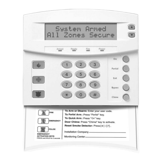
Lcd code pad
Hide thumbs
Also See for NetworX Series:
- Installation and start-up manual (80 pages) ,
- Installation and startup manual (20 pages) ,
- Manual (18 pages)

Related Manuals for GE NetworX Series


Summary of Contents for GE NetworX Series
- Page 1 ™ NetworX Series NX-148E LCD Code pad Installation and Setup Manual (Australian & New Zealand version)
- Page 2 Market Manager GE Interlogix, Melbourne, Australia. This document contains proprietary information of GE Interlogix and is furnished to its distributor and their customers solely to assist that customer in the installation, testing, operations, and/or maintenance of the equipment described.
-
Page 3: Table Of Contents
Table of Contents Entering the Program Mode Selecting the Module to Program Programming a Feature Numerical Data............................4 Binary Data............................... 5 Character Data ............................5 Loading Factory Defaults Enrolling Programming the Code Pads Using the Function Menu ......................... 7 Adjusting the LCD Contrast & Brightness....................8 Custom Messages ............................. -
Page 4: Entering The Program Mode
1. Entering the Program Mode Action Result Enters the program mode. On Bypass Partial Exit & Chime LEDs will flash. Prompts for the programming code. If the ‘Go To Program Code’ is valid, the LCD Go To Program Code screen will prompt for the device address to program. Factory default is You are now in the program mode and ready to select the module. -
Page 5: 3B. Binary Data
3b. Binary Data The top line of the display will show the current feature number on the left and the segment number on the right. The data will be displayed on the bottom line with the numbers 1-8 in the first 8 characters. If the number appears, this binary switch is on. -
Page 6: Loading Factory Defaults
Table 3-1 English Characters ù ‘ & < º > » Table 3-2 English Library ALARM DETECTOR GARAGE LIBRARY SMOKE VAULT AREA DINING GLASSBREAK LIGHT PORCH SOUND WAREHOUSE AUDIO DOOR GUEST LIVING ROOM SOUTH WEST BACK DOWN HALL MASTER RUMPUS STAIRS WINDOW BATHROOM... -
Page 7: Enrolling
5. Enrolling For supervision purposes, the NetworX control panel has the ability to automatically find and store in its memory the presence of all code pads, zone expanders, wireless receivers, and any other module connected to the data terminal. This allows these modules to be supervised by the control panel. Note: All modules should be connected and set to unique addresses prior to enrolling modules. -
Page 8: 6B. Adjusting The Lcd Contrast & Brightness
Table 6-1 Function Menu Function Result Function Result Adjust code pad tone Reset function Temp Master Mode Log review View zone status Adjust view / brightness of LCD Service menu Programming custom messages View alarm memory Set code pad options Test function Set code pad number and area Display test function... -
Page 9: 6D. Custom Messages In Language 2
The messages (custom, zone, and shutdown) are transferred to other LCD code pads after this mode is exited. All code pads must be addressed and enrolled for this to happen. Use the function to set the code pad numbers prior to programming custom messages. If a code pad is added after messages are programmed, you should either program all messages in it, or enter custom message programming on an existing code pad and make changes. -
Page 10: 6E. Set Code Pad Options
6e. Set Code Pad Options Action Result Prompts to ‘Please Enter Your Code’. The LCD will now prompt you through the options [program code] listed on the following chart. The current state of the option will be shown in the lower right corner of the display. Advances to the next option without making changes. -
Page 11: 6F. Set Code Pad Number And Area
6f. Set Code Pad Number and Area Action Result Prompts to ‘Please Enter Your Code’. Prompts for the code pad number. [program code] The current code pad number will be displayed in the lower right hand corner. Prompts for the area number. [code pad number] The current area will be displayed in the lower right hand corner. - Page 12 Possible Log Messages Display Description Txlobat Transmitter Low Battery - The transmitter has a low battery. ZN Lost Zone Lost - A wireless or multiplexed zone device is not reporting to the control. Duress Duress - The control has been armed or disarmed with a duress code. Man Fire Manual Fire - Code pad ‘Fire’...
-
Page 13: 7B. Set Elapsed Time In Minutes Since Last Autotest
7b. Set Elapsed Time in Minutes Since Last Autotest Action Result Prompts for a code. Displays the elapsed time screen. [program code] [100's digit] [10's digit] [1's digit] (example only) Saves and exits. 7c. Set System Time and Date Action Result Prompts to ‘Please Enter Your Code’. -
Page 14: 7E. View Zone Status
7e. View Zone Status Action Result Displays the zone status. Displays the list of all zones in sequential order by zone number. Exits the mode. 7f. View Alarm Memory Action Result Displays the zone descriptions. Displays the alarm memory list in sequential order by zone number. -
Page 15: 7I. Light Control For X-10 Devices
7i. Light Control for X-10 Devices When used in conjunction with an X-10 output device such as the NetworX NX-507E, NX-508E, NX-534E or NX-540E, this menu allows the user to control up to ten X-10 devices from each code pad. Action Result Prompts to ‘Select Light Number 0-9’. -
Page 16: 7L. Changing User Codes
7l. Changing User Codes For systems with areas - someone changing the code of another person must have access to all or more areas than the user being changed. Action Result Prompts ‘Please Enter Your Code’. Prompts for a user number. [master code] Prompts for a new code. -
Page 17: 7N. Reset Function
Default allows access to all areas. [Area number] The first key press will remove access to the area. To reestablish access, press the area number again. Saves data. Prompts for next user code. Return to step 3 to program another user code. Exits this mode. -
Page 18: Multi Area Systems Operation
8. Multi Area Systems Operation 8a. Master Mode The LCD code pad can be programmed to operate all system areas simultaneously. To set the multi-area mode, use the function as described on page 10, and answer ‘Yes’ to the question ‘Master code pad?’... - Page 19 Arming and Disarming Multiple Areas To arm/disarm multiple areas, enter a code that has arm/disarm Disarm º 12-45--8 authority for all of the areas to be armed/disarmed. A display similar to º --3--67- the one on the left will appear on the LCD screen. Top line of display = disarmed areas to which this code has access Bottom line of display = areas that are armed Table 8-1 List of Possible Conditions...
-
Page 20: 8E. Bypass In The Multi Area Mode
Silencing Alarms in the Multi-Area Mode If the code pad is sounding an alarm or the siren is running, it can be silenced by entering a code with the authority for the area(s) that are in alarm. The Exit, Bypass and Alarm Memory function keys will only work if an individual area is selected. -
Page 21: Service Display
9. Service Display The following message will be displayed periodically if the security system requires service. If you see this display, press One or more of the Service Required following fault messages will be displayed. Use the scroll keys Type 2 for help to browse through them. - Page 22 Expansion The main power to an expansion power supply is not on. Power Trouble Expansion An expansion power supply has a low battery. Low Battery Expansion A box containing an expansion device has been opened. Box Tamper Expansion A radio receiver is being jammed by another RF device. RF Jammed Expansion An expansion device or code pad is not reporting to the control...
-
Page 23: Device Numbers For Reporting
10. DEVICE NUMBERS FOR REPORTING The following table provides the device numbers that will be reported for trouble conditions. Table 10-1 Code Area 11. Maximum Wire Run Maximum total wire run is 800 meters using 14/020 cable. These numbers are for one code pad at the end of the wire. -
Page 24: Specifications
Shipping Weight 0.91grams When installed as directed, this product conforms to the standards set by Standards Australia on behalf of the Australian Communications Authority (ACA). GE Interlogix Australia 646 Whitehorse Rd Mitcham, Victoria, 3132 Tel. (03) 9259 4700 Fax. (03) 9259 4799 www.gesecurity.com.au...