Siemens SIMATIC Series Operating Instructions Manual
Hide thumbs
Also See for SIMATIC Series:
- Manual (118 pages) ,
- Getting started (46 pages) ,
- Product information (12 pages)
Table of Contents
Quick Links
SIMATIC IPC547G
SIMATIC
Industrial PC
SIMATIC IPC547G
Operating Instructions
04/2020
A5E49948632-AA
Preface
Overview
Safety instructions
Installing and connecting the
device
Commissioning the device
Expanded device functions
Expanding and assigning
parameters to the device
Device maintenance and
repair
Technical specifications
Technical support
List of abbreviations
Markings and symbols
1
2
3
4
5
6
7
8
A
B
C
Table of Contents

Related Manuals for Siemens SIMATIC Series


Summary of Contents for Siemens SIMATIC Series
- Page 1 SIMATIC IPC547G Preface Overview SIMATIC Safety instructions Installing and connecting the device Industrial PC SIMATIC IPC547G Commissioning the device Expanded device functions Operating Instructions Expanding and assigning parameters to the device Device maintenance and repair Technical specifications Technical support List of abbreviations Markings and symbols 04/2020 A5E49948632-AA...
- Page 2 Note the following: WARNING Siemens products may only be used for the applications described in the catalog and in the relevant technical documentation. If products and components from other manufacturers are used, these must be recommended or approved by Siemens. Proper transport, storage, installation, assembly, commissioning, operation and maintenance are required to ensure that the products operate safely and without any problems.
-
Page 3: Preface
Preface These operating instructions contain all the information you need for commissioning and operation of the SIMATIC IPC547G. It is intended both for programming and testing personnel who commission the device and connect it with other units (automation systems, programming devices), as well as for service and maintenance personnel who install add-ons or carry out fault/error analyses. - Page 4 Preface Figures This document contains figures for the described device. The supplied device may differ in some details from the figures. ① ② ③ ● Portions of the figure referenced in the text are marked with item numbers: etc. ● Work steps within the figures are marked with process numbers according to the order in which they have to be performed: ,…...
-
Page 5: Table Of Contents
Table of contents Preface ..............................3 Overview..............................9 Product description ........................9 1.1.1 Scope of application........................ 10 1.1.2 Highlights ..........................11 1.1.3 Features ..........................12 Device configuration ....................... 17 1.2.1 Interfaces ..........................20 1.2.2 Operator controls ........................23 1.2.3 Status displays ........................25 Accessories .......................... - Page 6 Table of contents 4.4.4 RAID systems ........................60 4.4.4.1 Manage RAID system ......................60 4.4.4.2 RAID1 system ........................61 4.4.4.3 RAID5 system ........................61 4.4.4.4 RAID system with hot spare drive ..................61 Windows Action Center ......................62 Switching off the device ......................63 Expanded device functions ........................
- Page 7 Table of contents Device maintenance and repair ......................103 Repair information ......................... 103 Maintenance ......................... 104 7.2.1 Maintenance intervals ......................104 7.2.2 Remove the fan cover ......................105 7.2.3 Replacing filters ........................105 Manage onboard RAID system ..................... 107 7.3.1 Example for a RAID1 system during the boot phase of the system ........
- Page 8 Table of contents Dimension drawings ......................145 8.3.1 Dimension drawing of the device ..................145 8.3.2 Dimension drawing of the expansion cards ................. 147 8.3.3 Dimension drawing of the telescope rails ................147 Technical specifications ....................... 149 8.4.1 General technical specifications ..................149 8.4.2 Current and power requirements ..................
-
Page 9: Overview
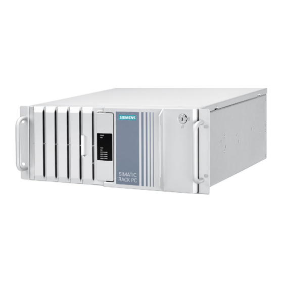
Overview Product description Note Depending on the configuration ordered the features and illustrations described in this manual may differ from the features of your device. The SIMATIC IPC547G is a powerful industrial PC in 19" rack format design (4 HE). It is perfectly suited for high-performance industrial PC applications. -
Page 10: Scope Of Application
Overview 1.1 Product description Device with short enclosure (enclosure depth 356 mm) 1.1.1 Scope of application The SIMATIC IPC offers system integrators, cabinet designers, system engineers and machine designers a 19" rack PC platform for high-performance applications and IT applications on the control and cell level for: ●... -
Page 11: Highlights
Overview 1.1 Product description 1.1.2 Highlights The latest PC technology ● State-of-the-art Intel technology, 6th Generation Intel Core™ i processors ® ® ● Maximum performance and scalability, independent of the enclosure version ● Expansion card slots 2 × PCIe x16, 1 × PCIe x8, 2 × PCIe x4, 2 × PCI ●... -
Page 12: Features
Overview 1.1 Product description 1.1.3 Features Note Please take note of the version ordered Depending on the configuration ordered the features and illustrations described in this manual may differ from the features of your device. Basic data Device with standard enclosure Device with short enclosure Design 19"... - Page 13 Overview 1.1 Product description Device with standard enclosure Device with short enclosure Interfaces See section "Interfaces (Page 20)". Drive bays On the front: Internal: • • – 4 × slimline removable trays in the drive – 2 × 3.5" cage type A or –...
- Page 14 Overview 1.1 Product description Installation options of drives in a short enclosure Drive bay plate Basic design On a drive bay plate on the front, see section "Install and replace the internal hard disk, short enclosure (Page 85)" and "Installing and replacing SSDs, short enclosure (Page 87)". Number of drives for 2 (3.5"/2.5") internal, robust instal-...
- Page 15 Overview 1.1 Product description Operating system Device with standard enclosure Device with short enclosure Operating system Without • Pre-installed, included on Restore DVD: • – Microsoft Windows 7 Ultimate, 64-bit, MUI – Microsoft Windows 7 Ultimate, 32-bit, MUI – Microsoft Windows Server 2008 R2, 64-bit, including 5 clients, MUI –...
- Page 16 Overview 1.1 Product description Operating system languages The following languages for the operating system can be installed at a later time: Windows Server 2008 Windows Server 2012 Windows Server 2016 Windows 7 Windows Server 2019 (32 Bit / 64 Bit) Windows 10 2015 LTSB Windows 10 2016...
-
Page 17: Device Configuration
Overview 1.2 Device configuration Device configuration Front panel SIMATIC IPC547G Operating Instructions, 04/2020, A5E49948632-AA... - Page 18 Overview 1.2 Device configuration Example with drive cage type A ① Fan cover Fan cover with openings for ventilation of the device ② Status displays See section "Status displays (Page 25)" ③ Front door Lockable front door that provides protection against unauthorized access. ⑪...
- Page 19 Overview 1.2 Device configuration Rear of the device Device with motherboard D3446-S Device with motherboard D3445-S ① Power supply See section "Interfaces (Page 20)", power supply connection ② Interfaces See section "Interfaces (Page 20)" ③ Air outlet ④ Expansion card slots •...
-
Page 20: Interfaces
Overview 1.2 Device configuration 1.2.1 Interfaces Interfaces Device with motherboard D3446-S Device with motherboard D3445-S ① COM2 Serial interface 2 (V.24), 9-pin D-sub socket (optional) ② Mouse Connection for a PS/2 mouse ③ Keyboard Connection for a PS/2 keyboard ④ USB 2.0 Connections for USB devices ⑤... - Page 21 Overview 1.2 Device configuration ⑧ Parallel interface, 25-pin (optional) ⑨ 2 × USB 3.0 Connections for USB devices, backward compatible with USB 2.0/1.1 ⑩ LAN 1 RJ45 Ethernet connections for 10/100/1000 Mbps LAN 2 LAN 1 is iAMT capable (only in combination with motherboard D3446-S) ⑪...
- Page 22 Overview 1.2 Device configuration 20-pin DisplayPort connector (3.3 V; 500 mA) Audio 3.5 mm Audio Jack Plug Line IN (light blue) • Headphone OUT (lime) • (max. 1.2 V @ 32 ohm) Microphone IN (pink) • PS/2 6-pin PS/2 socket (5 V;...
-
Page 23: Operator Controls
Overview 1.2 Device configuration Power supply connections In the following figure the AC connections of the power supply are marked, on the left for devices with a single power supply and on the right with redundant power supply: NOTICE Incompatible enclosure Conversion from one power supply type to another is not possible. - Page 24 Overview 1.2 Device configuration On/Off switch and alarm reset button The following figures show the location of the on/off switch on the rear of the device for devices with simple or redundant power supply. The alarm reset button is only available for devices with redundant power supply.
-
Page 25: Status Displays
Overview 1.2 Device configuration 1.2.3 Status displays Front status displays The status displays integrated in the front door provide information on the status of the device components listed in the following table. Item Status dis- Meaning Description play ① POWER Operating mode of the PC Switched off or disconnected from the mains YELLOW... - Page 26 Overview 1.2 Device configuration only ⑦ HDD2 Alarm All RED LEDs are RAID synchronization running, RAID is not flashing HDD3 Alarm ⑧ The hard disk newly integrated in case of error is synchronized with an existing hard disk. All RED LEDs are RAID is not OK lit up The faulty drive could not be localized by the...
- Page 27 Overview 1.2 Device configuration ● Redundant power supply Status display Meaning Status Meaning of the status Status LED (see Status of the power Module is out of service, no • marking) supply module redundancy in effect. GREEN The module is in operation •...
-
Page 28: Accessories
Accessories are available for your device. These are not included in the scope of delivery. Information on available accessories is listed in the table below and on the Internet at the following addresses: ● Industry Mall (https://mall.industry.siemens.com) ● IPC expansion components (http://www.automation.siemens.com/mcms/pc-based-... - Page 29 Overview 1.3 Accessories Name Description Device Device Article number / MLFB with with short standard enclosure enclosure Low profile The removable tray makes for quick and 6ES7648-0EH00-1BA0 removable rack simple replacement of a 2.5" or 3.5" drive unit without having to open the device or re- move it from the control cabinet.
- Page 30 Overview 1.3 Accessories SIMATIC IPC547G Operating Instructions, 04/2020, A5E49948632-AA...
-
Page 31: Safety Instructions
Safety instructions General safety instructions Risk of physical injury CAUTION Risk of physical injury The device is heavy and may injure persons and be damaged if it falls. • Use the handles on the front panel of the device to carry and lift the device. Risk due to electric shock WARNING Risk of electric shock... - Page 32 Safety instructions 2.1 General safety instructions Devices in the control cabinet WARNING Life-threatening voltages are present with an open control cabinet When you open the control cabinet, some areas or components may be carrying life- threatening voltages. If you touch these areas or components, you may be killed by electric shock. Switch off the power supply to the cabinet before opening it.
- Page 33 Safety instructions 2.1 General safety instructions Battery WARNING Risk of explosion and release of harmful substances Improper handling of lithium batteries can result in an explosion of the batteries. Explosion of lithium batteries and the released pollutants can cause serious physical injury. Damaged batteries jeopardize the function of the device.
- Page 34 Siemens’ products and solutions undergo continuous development to make them more secure. Siemens strongly recommends that product updates are applied as soon as they are available and that the latest product versions are used. Use of product versions that are no longer supported, and failure to apply latest updates may increase customer’s exposure to...
-
Page 35: Notes On Use
Safety instructions 2.2 Notes on use Protection against access by unauthorized persons An unauthorized user can operate the device incorrectly and bypass logon by restarting the device. Operator actions by unauthorized persons jeopardize operational reliability. Take the following safety precautions: •... - Page 36 Safety instructions 2.2 Notes on use NOTICE Rack-mount instructions A) Elevated Operating Ambient - If installed in a closed or multi-unit rack, the operating ambient temperature of the rack environment may be greater than the room ambient. Therefore consideration should be given to installing the equipment in an environment compatible with the maximum ambient temperature (Tma) specified by the manufacturer.
- Page 37 Safety instructions 2.2 Notes on use NOTICE Ambient conditions and chemical resistance Unsuitable environmental conditions can cause faults or damage the device. Failure to comply nullifies the warranty in accordance with IEC/EN/UL/CSA 61010-2-201. • Operate the device only in closed rooms. •...
- Page 38 Safety instructions 2.2 Notes on use SIMATIC IPC547G Operating Instructions, 04/2020, A5E49948632-AA...
-
Page 39: Installing And Connecting The Device
Installing and connecting the device Preparing for installation 3.1.1 Checking the delivery package Procedure 1. When accepting a delivery, please check the packaging for visible transport damage. 2. If any transport damage is present at the time of delivery, lodge a complaint at the shipping company in charge. - Page 40 Installing and connecting the device 3.1 Preparing for installation 6. Please inform the delivery service immediately if the package contents are incomplete or damaged or do not correspond with your order. Fax the enclosed form "SIMATIC IPC/PG Quality Control Report". DANGER Electric shock and fire hazard due to damaged device A damaged device can be under hazardous voltage and trigger a fire in the machine or...
-
Page 41: Device Identification Data
Installing and connecting the device 3.1 Preparing for installation 3.1.2 Device identification data The device can be clearly identified with the help of this identification data in case of repairs or loss. The following illustrations are examples. The data of your device may differ from the data in these examples. -
Page 42: Mounting The Device
Installing and connecting the device 3.2 Mounting the device Identification date Source Value Microsoft Windows Product Key COA label Ethernet address 1, MAC address BIOS setup > "Main" menu Ethernet address 2, MAC address Component label 1. Copy the order number, serial number and manufacturing version in the table listed above. -
Page 43: Mounting Location And Position
Installing and connecting the device 3.2 Mounting the device Note The device meets the requirements for fire protection enclosures in accordance with IEC/EN/UL/CSA 61010-2-201. You can therefore install it without an additional fire protection enclosure. ● Install the device only in one of the described permitted mounting positions. ●... - Page 44 Installing and connecting the device 3.2 Mounting the device The systems meets the requirements according to IEC60297_3_100. CAUTION Risk of physical injury The device is too heavy to be mounted exclusively with the 19-inch brackets of the front panel. The device may fall down, injure people and get damaged. Secure the device using additional measures.
-
Page 45: Connecting The Device
Installing and connecting the device 3.3 Connecting the device Connecting the device 3.3.1 Connection information WARNING Risk of fire and electric shock The on/off button and on/off switch do not fully disconnect the device from the mains. If the device is switched off with the on/off switch, there remains a risk of electric shock and fire hazard, for example, if the device or connection cables are damaged or if the device is used improperly. - Page 46 Installing and connecting the device 3.3 Connecting the device WARNING Operation only in TN networks The device is designed exclusively for operation on grounded power supply systems (TN networks per VDE 0100 Part 100 or IEC 60364-1). Operation with non-grounded or impedance-grounded systems is not permitted.
-
Page 47: Connection Of Equipotential Bonding Line
Installing and connecting the device 3.3 Connecting the device 3.3.2 Connection of equipotential bonding line A low-impedance earth connection ensures that interference signals generated by external power supply cables, signal cables or other cables to the I/O devices are safely discharged to earth. -
Page 48: Connecting The Power Supply
Installing and connecting the device 3.3 Connecting the device 3.3.3 Connecting the power supply Please observe before connecting WARNING Injury to persons or damage to property when operated on an incorrect power supply system If you connect the device to an unsuitable power supply, the device receives voltages and currents that are too high or too low. - Page 49 Installing and connecting the device 3.3 Connecting the device Ensure that the device connectors, connection sockets and connection materials are rated for the maximum current input and ambient temperature of the device and meet the requirements of the following standards: ●...
-
Page 50: Connecting Peripheral Equipment
Installing and connecting the device 3.3 Connecting the device Connecting a redundant power supply ② 1. Make sure that the on/off switch is in the '0' position. ③ 2. Connect a power cable to the two sockets ② 3. Switch on the two on/off switches ①... -
Page 51: Securing The Cables
Installing and connecting the device 3.3 Connecting the device Note Wait at least ten seconds before you reinsert USB devices. Note that the EMC immunity of standard USB devices is designed only for office environments. These USB devices are appropriate for handling commissioning and service tasks. -
Page 52: Connecting The Device To Networks
Control level. Information on this can be found on the SIMATIC NET Manual Collection CD. The software package and the documentation are not included in the scope of delivery. Additional information You can find additional information on the Internet at: Technical support (https://support.industry.siemens.com/cs/ww/en/) SIMATIC IPC547G Operating Instructions, 04/2020, A5E49948632-AA... -
Page 53: Multi-Monitoring
Installing and connecting the device 3.3 Connecting the device 3.3.7 Multi-monitoring You can operate up to five monitors simultaneously (for a device with motherboard D3445-S: up to 4 monitors) at the interfaces of the integrated graphics controller in combination with the optional graphics card. - Page 54 Installing and connecting the device 3.3 Connecting the device SIMATIC IPC547G Operating Instructions, 04/2020, A5E49948632-AA...
-
Page 55: Commissioning The Device
Commissioning the device General information on commissioning Requirements for commissioning The following requirements have to be met before you can start commissioning: ● I/O devices, keyboard, mouse and monitor are connected. ● The power supply is connected. ● An operating system is installed. The device can be supplied without an operating system. -
Page 56: Automatic Switching On Of The Device
Commissioning the device 4.3 Automatic switching on of the device 4. Make the required region and language settings. If you want your system language to be international, select English. Information for subsequent changing of the region and language settings, see the section "Setting up the language selection using the Multilanguage User Interface (MUI) (Page 135)". -
Page 57: Notes On Various Device Configurations
Commissioning the device 4.4 Notes on various device configurations Notes on various device configurations 4.4.1 DVD burner drive The DVD burner drive is an optional device feature. Recording methods supported by the disk drive: ● Disc-At-Once ● Track-At-Once ● Session-At-Once ●... -
Page 58: Hard Disks In Removable Tray
Commissioning the device 4.4 Notes on various device configurations 4.4.2 Hard disks in removable tray The hard disks in the removable tray can be replaced during operation in connection with RAID (hot swap). Requirement ● A hard disk of the same interface type Always replace the defective hard disk with a new one of the same interface type and capacity. -
Page 59: System With Two Drives
Commissioning the device 4.4 Notes on various device configurations 6. Fold back the tray bracket until it rests completely against the removable tray. ① The power supply LED must be on. ② 7. Close the lock with the appropriate key. Note Always lock the removable tray to ensure reliable operation of a device with a removable tray. -
Page 60: Raid Systems
Commissioning the device 4.4 Notes on various device configurations 4.4.4 RAID systems 4.4.4.1 Manage RAID system RAID system management functions The RAID system is fully set up ex works. The installed SIMATIC diagnostic software is used to display the status of the RAID system. Additional software is not required. Detailed information on drive replacement is available in section "Expansion and parameter assignment of device", "Replace defective hard disk in RAID system". -
Page 61: Raid1 System
Commissioning the device 4.4 Notes on various device configurations 4.4.4.2 RAID1 system This is a RAID1 system configuration (data mirroring with two drives). This means that if there is a defective hard disk or there are cable problems, the system can continue to operate in one channel and achieve a high degree of availability. -
Page 62: Windows Action Center
Commissioning the device 4.5 Windows Action Center Windows Action Center The Action Center checks the status of the device with regard to the important safety aspects listed below. If a problem is found, the Action Center provides recommendations on how you can better protect the device. Functions ●... -
Page 63: Switching Off The Device
Commissioning the device 4.6 Switching off the device Switching off the device Shutting down the operating system For Windows operating systems: 1. Click on a free area of the Windows Desktop with the left mouse button. Alternatively, press the key combination - Page 64 Commissioning the device 4.6 Switching off the device Hardware reset You can perform a hardware reset to restart the device when the operating system no longer responds to input from the keyboard or mouse. The operating system is not safely shut down in this case.
-
Page 65: Expanded Device Functions
Expanded device functions Monitoring functions 5.1.1 Overview of the monitoring functions SIMATIC IPC DiagBase software Even in its basic version, the device supports the use of monitoring functions. The SIMATIC IPC DiagBase software, which is included in the scope of delivery, provides the following local display, monitoring and control functions: ●... -
Page 66: Temperature Monitoring And Temperature Display
Expanded device functions 5.1 Monitoring functions 5.1.2 Temperature monitoring and temperature display The temperature is detected at critical device locations by temperature sensors. A temperature sensor monitors the processor temperature. Other temperature sensors monitor further critical points. If the set temperature threshold is exceeded at a temperature sensor, the following reactions are triggered: ●... -
Page 67: Fan Monitoring
Expanded device functions 5.1 Monitoring functions 5.1.3 Fan monitoring The operation of front fans, CPU, dual-head graphic card fans, power supply fans and fans on the drive cage type A are monitored by SIMATIC monitoring software. If a fan fails, the following reactions are triggered: ●... -
Page 68: Battery Monitoring
Expanded device functions 5.1 Monitoring functions NOTICE "Reset on" option The "Reset on" option immediately triggers a hardware reset that may result in loss of data under Windows and damage to the installation. Watchdog monitoring times The monitoring time can be configured with the DiagBase or DiagMonitor software. Note When you change the monitoring time, the change becomes effective immediately. -
Page 69: Active Management Technology (Amt)
SIMATIC IPC Remote Manager The "SIMATIC IPC Remote Manager" software is available for utilization of the AMT functions with SIMATIC IPCs. The software can be ordered from the Siemens online ordering system. For detailed information about "SIMATIC IPC Remote Manager", refer to the corresponding product documentation:SIMATIC IPC Remote Manager (http://support.automation.siemens.com/WW/view/en/48707158) -
Page 70: Trusted Platform Module (Tpm)
Expanded device functions 5.3 Trusted Platform Module (TPM) Trusted Platform Module (TPM) Depending on the ordered configuration of your device, a Trusted Platform Module according to Standard TPM V2.0 may be available. The Trusted Platform Module is a chip that enhances your device with security functions. -
Page 71: Expanding And Assigning Parameters To The Device
Expanding and assigning parameters to the device Information on expansions The permissible expansion of the device is described below, as well as the resulting permissible operating conditions. Installation of expansions WARNING Unauthorized opening and improper repairs or expansions on the device may result in substantial damage to equipment or endanger the user. -
Page 72: Drives
Expanding and assigning parameters to the device 6.1 Information on expansions See also ESD guideline (Page 143) Spare parts and repairs (http://support.automation.siemens.com/WW/view/en/16611927) 6.1.1 Drives Drives can be installed in the standard enclosure as follows: ● In the drive cage type A for operable drives in the removable tray ●... - Page 73 Expanding and assigning parameters to the device 6.1 Information on expansions If the device is permanently installed or mounted on telescopic rails, it must not be subjected to vibration stress during operation. The restrictions do not apply for the use of SSD. Motherboard Number of drives AHCI...
-
Page 74: Permissible Expansion For Temperature Range 0 To 40 °C
Expanding and assigning parameters to the device 6.1 Information on expansions 6.1.1.2 Permissible expansion for temperature range 0 to 40 °C Enclosure variant with drive cage type A ① Drive in 5.25" adapter for removable tray ② Drive in removable tray ③... - Page 75 Expanding and assigning parameters to the device 6.1 Information on expansions Enclosure variant with drive cage type B ① Drive in drive bay for internal robust installation ② Hard disk type "Enterprise" is possible The maximum permitted power loss of the expansion cards is 80 W. If the device is permanently installed or mounted on telescopic rails, it may be subjected to the following vibration stress during operation: ●...
-
Page 76: Opening The Front Door
Expanding and assigning parameters to the device 6.2 Opening the front door Opening the front door Procedure 1. Open the front door with the key. 2. Pull the front door to the side. Open the device NOTICE Malfunctions and electric shock Improper intervention in the device endangers operational reliability and may damage the device. -
Page 77: Memory Expansion
Expanding and assigning parameters to the device 6.4 Memory expansion Requirement ● The front door is open; see "Opening the front door (Page 76)". ● The device is fully disconnected from the mains voltage; see section "Switching off the device (Page 63)". ●... -
Page 78: Installing Expansion Cards
Expanding and assigning parameters to the device 6.5 Installing expansion cards Installing expansion cards Note the following: ● Specification of the expansion cards The device is designed for the following types of expansion cards: – PCI specification 2.3 – PCIe Gen 2, expansion cards of the PCIe type Gen 1 and Gen 2 are supported. –... -
Page 79: Drives
Expanding and assigning parameters to the device 6.6 Drives Procedure ① 1. Hold the bar with the card retainer on both ends and remove it by pulling it upwards. The bar is latched on both ends. ② 2. Remove the slot bracket for the required slot. -
Page 80: Removing And Installing A 3.5"/2.5" Drive In Drive Cage Type B
Expanding and assigning parameters to the device 6.6 Drives 6.6.2 Removing and installing a 3.5"/2.5" drive in drive cage type B Requirement ● The device is equipped with the drive cage type B. ● The device is fully disconnected from the mains voltage; see section "Switching off the device (Page 63)". - Page 81 Expanding and assigning parameters to the device 6.6 Drives ② 3. As shown below, remove the left and right drive mounting bars laterally and the drive ② bay cover from the front. Note: The mounting bars are labeled with "L" and "R" and must be remounted in the ③...
- Page 82 Expanding and assigning parameters to the device 6.6 Drives ② 7. Attach the left and right drive mounting bars as shown. ① 8. Push the drive bay in the guide rail on the left and right 3/4 into the drive cage evenly without tilting.
-
Page 83: Removing And Installing The Hard Disk Or Ssd In The Removable Tray
Expanding and assigning parameters to the device 6.6 Drives 6.6.3 Removing and installing the hard disk or SSD in the removable tray Requirement ● The device is equipped with the drive cage type A. ● If there is no RAID: The device is fully disconnected from the mains voltage, see section "Switching off the device (Page 63)". - Page 84 Expanding and assigning parameters to the device 6.6 Drives Installation 1. Carefully insert the new drive into the removable tray. Take care not to touch the contacts of the drive when you do this. 2. Fasten the new drive with the screws to the base of the removable tray. Only use the original screws.
-
Page 85: Install And Replace The Internal Hard Disk, Short Enclosure
Expanding and assigning parameters to the device 6.6 Drives 6.6.4 Install and replace the internal hard disk, short enclosure Requirement ● The device is fully disconnected from the mains voltage, see section "Switching off the device (Page 63)". ● The device is open, see the chapter "Open the device (Page 76)". ●... - Page 86 Expanding and assigning parameters to the device 6.6 Drives ① ② 3. Remove the design cover from the drive bay plate ③ ④ 4. Loosen the 4 highlighted fixing screws on slot of the respective hard disk drive. Installation 1. Proceed in reverse order. See also Device configuration (Page 17) SIMATIC IPC547G...
-
Page 87: Installing And Replacing Ssds, Short Enclosure
Expanding and assigning parameters to the device 6.6 Drives 6.6.5 Installing and replacing SSDs, short enclosure Requirement ● The device is fully disconnected from the mains voltage, see section "Switching off the device (Page 63)". ● The device is open, see the chapter "Open the device (Page 76)". ●... - Page 88 Expanding and assigning parameters to the device 6.6 Drives ① ② 3. Remove the design cover from the drive bay plate ③ ④ 4. Loosen the 4 highlighted fixing screws on slot of the respective hard disk drive. Installation 1. Proceed in reverse order. SIMATIC IPC547G Operating Instructions, 04/2020, A5E49948632-AA...
-
Page 89: Hard Disk Or Ssd, Device With Drive Cage Type A
Expanding and assigning parameters to the device 6.6 Drives 6.6.6 Hard disk or SSD, device with drive cage type A Requirement ● The device is equipped with the drive cage type A. ● The device is fully disconnected from the mains voltage, see section "Switching off the device (Page 63)". - Page 90 Expanding and assigning parameters to the device 6.6 Drives ⑤ ⑥ 5. Insert the new adapter module for the removable tray into the drive bay from the front and snap it into place at the back. Check the following: ⑤ –...
-
Page 91: Installing A Hard Disk Or Ssd In Slot 3
Expanding and assigning parameters to the device 6.6 Drives 6.6.6.2 Installing a hard disk or SSD in slot 3 ① Drive bay cover Procedure ① 1. Unlock the slot cover by pressing laterally against the surfaces and pushing the ② mounting bar forwards from the device in the direction of the arrow . -
Page 92: Install / Replace Internal Hard Disk/Ssd On The Side Panel (Standard Enclosure Only)
Expanding and assigning parameters to the device 6.6 Drives 2. Push the 5.25" adapter for the removable rack unit shown below from the front into the drive cage. 3. Connect the SATA cables to the required SATA connectors of the motherboard and to the adapter module of the new 5.25"... - Page 93 Expanding and assigning parameters to the device 6.6 Drives 2. Screw from outside the drive bay plate on the inside to the side wall of the enclosure, at ① ② ③ position or position . The SATA connections each lie in the middle 3.
-
Page 94: Replacing A Defective Hard Disk Drive In The Raid System
Expanding and assigning parameters to the device 6.6 Drives 6.6.7 Replacing a defective hard disk drive in the RAID system Hard disks can be replaced during operation in the removable tray in connection with a configured RAID1 system or RAID5 system. This functionality is referred to as "Hot Swap". Note If you have configured a non-RAID system with several hard disk drives, you need to turn off the device before you replace a hard disk drive. - Page 95 Expanding and assigning parameters to the device 6.6 Drives Similar to figure ① Removable tray 1 ② Removable tray 0 ③ "Power" LED; power supply available ④ "HDD" LED, access to hard disk drive Status displays of the hard disk drives in a RAID1 system A defective hard disk drive in the RAID system is signaled with the status displays at the front of the device.
- Page 96 Expanding and assigning parameters to the device 6.6 Drives Mounting locations for hard disk drives in the RAID5 system Unlike a RAID1 system, hard disk drives can only be installed on the front in the removable tray for a RAID5 system. Note Replacement of a hard disk drive in the removable tray and in the RAID system can be performed without switching off the device.
-
Page 97: Inserting The 5.25" Drive In The Drive Cage Type B
Expanding and assigning parameters to the device 6.6 Drives Status displays of the hard disk drives in a RAID5 system A defective hard disk drive in the RAID system is displayed by the status displays at the front of the device. The following table includes information on the alarms of the status displays. - Page 98 Expanding and assigning parameters to the device 6.6 Drives Procedure Installing a drive 1. Remove the drive cover of the free slot, see section "Removing and installing a 3.5"/2.5" drive in drive cage type B (Page 80)" or "Removing and installing the hard disk or SSD in the removable tray (Page 83)".
- Page 99 Expanding and assigning parameters to the device 6.6 Drives Replacing the drive ① 1. Unlock the drive by pressing laterally against the surfaces and pushing the drive ② forward from the device in the direction of the arrow . Set the drive down carefully. 2.
-
Page 100: Removing And Installing A Dvd Drive
Expanding and assigning parameters to the device 6.6 Drives 6.6.9 Removing and installing a DVD drive Requirement ● The device is fully disconnected from the mains voltage; see section "Switching off the device (Page 63)". ● The device is open. ①... - Page 101 Expanding and assigning parameters to the device 6.6 Drives Procedure 1. Remove all SATA cables from the ① cable holder The outlined segment is enlarged in the next figure. 2. Unlock the DVD drive bay by pressing against the movable ②...
- Page 102 Expanding and assigning parameters to the device 6.6 Drives ③ 3. Grip the front of the DVD drive on the left and the right and pull it completely out of the device. 4. Carefully set down the DVD drive ④ in the drive bay , as shown.
-
Page 103: Device Maintenance And Repair
Device maintenance and repair Repair information Carrying out repairs Only qualified personnel are permitted to repair the device. WARNING Unauthorized opening and improper repairs on the device may result in substantial damage to equipment or endanger the user. • Always disconnect the power plug before you open the device. •... -
Page 104: Maintenance
● T6 screwdriver for removing and installing the DVD drive ● T10 screwdriver for all of the remaining screws See also ESD guideline (Page 143) Spare parts and repairs (http://support.automation.siemens.com/WW/view/en/16611927) Maintenance 7.2.1 Maintenance intervals To maintain high system availability, we recommend the preventative replacement of those PC components that are subject to wear in accordance with the intervals for replacement indicated in the table below. -
Page 105: Remove The Fan Cover
You may only use filters of the same type. Information about the original spare parts for SIMATIC PCs is available in the Internet at SIMATIC IPC after-sales information system (http://www.siemens.com/asis). Filter pads are available as a pack of 10 under the article number A5E37019277. - Page 106 Device maintenance and repair 7.2 Maintenance Note Use of the filter pad We advise against using filter pads that have already been used. If you do want to refit a filter pad you have removed, however, take account of the direction in which the fan draws air into the device.
-
Page 107: Manage Onboard Raid System
Device maintenance and repair 7.3 Manage onboard RAID system Manage onboard RAID system The RAID system is fully set up ex works. The installed SIMATIC diagnostic software is used to display the status of the RAID system. Additional software is not required. Additional information is available in the sections "RAID systems (Page 60)"... -
Page 108: Raid Software
Device maintenance and repair 7.3 Manage onboard RAID system 7.3.3 RAID software The RAID software "Intel Rapid Storage Technology" offers advanced functions to use and manage the RAID system. 1. Select the RAID software via "Start > Programs > Intel Rapid Storage Technology". 2. -
Page 109: Displaying A Defective Hard Disk Of A Raid System In The Raid Software
Device maintenance and repair 7.3 Manage onboard RAID system NOTICE Operator errors on the machine or plant Data is synchronized if a hard disk fails. Depending on the work load of the processor and hard disks, the system may react with some delay. Execution of keyboard, mouse or touch screen commands may be briefly delayed in extreme situations. -
Page 110: Special Feature: Replacing Hard Disk In The Raid System When Switched Off
Device maintenance and repair 7.3 Manage onboard RAID system 7.3.6 Special feature: Replacing hard disk in the RAID system when switched off The RAID system does not automatically boot up when restarted if a defective hard disk was replaced while the RAID system is switched off. Therefore, place the RAID system in the first place of the bootable sources in the BIOS setup menu "Boot". - Page 111 Device maintenance and repair 7.3 Manage onboard RAID system Manual integration of the hard disk (in the event of an error) 1. Select "Start" > "Programs" > "Intel Rapid Storage Technology". 2. Click "Run Hardware Scan now". The new hard disk is found and displayed. Click on the link "Rebuild to another Disk".
- Page 112 Device maintenance and repair 7.3 Manage onboard RAID system Display of the defective hard disk in the RAID software (in the event of an error) The defective hard disk being replaced remains displayed in the RAID software during the rebuild process. The defective hard disk is no longer displayed when the rebuild process is complete.
-
Page 113: Integrating A Hot Spare Hard Disk Drive In The Raid System
Device maintenance and repair 7.4 Removing and installing hardware 7.3.8 Integrating a hot spare hard disk drive in the RAID system If the hot spare hard disk drive was replaced in a RAID system, the new hot spare hard disk drive must be integrated in the RAID system once again. - Page 114 Device maintenance and repair 7.4 Removing and installing hardware Procedure Remove the fan support ① 1. Press the locks together and keep them pressed. ② 2. Lift the fan support slightly upwards from the bayonet fitting and remove it to the front from the front of the enclosure.
- Page 115 Device maintenance and repair 7.4 Removing and installing hardware Replace the fan in the fan support 1. Press on the clip on the small fan ① cable plug connector remove the connector from the ② larger adapter plug ② 2. Press on the side of the clips and loosen the adapter plug from the cable holder.
-
Page 116: Change The Fan On Drive Cage Type A
Device maintenance and repair 7.4 Removing and installing hardware 7.4.1.2 Change the fan on drive cage type A The fan is only installed in the removable tray (drive cage type A) for configurations with RAID and the hard disk type "Enterprise". Requirement ●... -
Page 117: Replacing The Backup Battery
● A lithium battery recommended by the manufacturer or one that is identical Information on original spare parts for SIMATIC IPCs is available at SIMATIC IPC after- sales information system (http://www.siemens.com/asis). Note Article number of the original spare part (lithium battery of the same type): A5E00369854 CR2032). -
Page 118: Removing The Power Supply
Device maintenance and repair 7.4 Removing and installing hardware 7.4.3 Removing the power supply Requirement ● The device is fully disconnected from the mains voltage, see section "Switching off the device (Page 63)". ● The device is open, see the section "Open the device (Page 76)". ●... -
Page 119: Replacing Redundant Power Supply Module
Device maintenance and repair 7.4 Removing and installing hardware 7.4.4 Replacing redundant power supply module If a module of the redundant power supply is defective, you can continue to operate the device until the device can be shut down in a controlled manner. The replacement of one of the two modules of the redundant power supply can be performed, however, without shutting down the device. -
Page 120: Removing The Redundant Power Supply
Device maintenance and repair 7.4 Removing and installing hardware 7.4.5 Removing the redundant power supply Requirement ● The device is fully disconnected from the mains voltage; see section "Switching off the device (Page 63)". ● The device is open; see section "Open the device (Page 76)". ●... -
Page 121: Removing The Motherboard
Device maintenance and repair 7.4 Removing and installing hardware 7.4.6 Removing the motherboard Requirement ● The device is fully disconnected from the mains voltage; see section "Switching off the device (Page 63)". ● The device is open; see section "Open the device (Page 76)". ●... - Page 122 Device maintenance and repair 7.4 Removing and installing hardware 4. Disconnect all cables from the motherboard. 5. Remove the screws that are marked in the figure below. Installation 1. For installation, follow the steps for removal in reverse order. 2. Update the BIOS to match the version of the motherboard. Please note during the update if you operate a device with or without a RAID system.
-
Page 123: Replacing The Processor
Only an approved processor is permitted to be installed on the motherboard of the device. Information about original spare parts for SIMATIC IPCs is available on the Internet at: – SIMATIC IPC after-sales information system (http://www.siemens.com/asis) – Contacts (http://www.siemens.com/automation/partner) NOTICE... - Page 124 Device maintenance and repair 7.4 Removing and installing hardware Procedure Removal 1. Remove the highlighted fan connector and loosen the four highlighted screws. The following figure shows the motherboard D3446 with the heat sink for the Xeon processor. 2. Remove the heat sink. SIMATIC IPC547G Operating Instructions, 04/2020, A5E49948632-AA...
- Page 125 Device maintenance and repair 7.4 Removing and installing hardware 3. Unlock the socket and lift the socket cover. 4. Remove the processor. Installation 1. Install the new processor on the socket, as shown in the figure. During positioning, make sure to take the highlighted arrow on the processor into consideration.
-
Page 126: Replace The Adapter Module For The Removable Tray
Device maintenance and repair 7.4 Removing and installing hardware 7.4.8 Replace the adapter module for the removable tray Requirement ● The device is equipped with the drive cage type A. ● The device is fully disconnected from the mains voltage; see section "Switching off the device (Page 63)". -
Page 127: Changing Drives
Device maintenance and repair 7.5 Installing the software 7.4.9 Changing drives See section "Drives (Page 79)". Installing the software 7.5.1 Sources for installation of the operating system If the operating system is faulty, you can reinstall it with one of these DVDs: ●... -
Page 128: Installing Drivers And Software
Device maintenance and repair 7.5 Installing the software other operating systems Contact the corresponding manufacturer. 7.5.3 Installing drivers and software Requirement You need the "Documentation and Drivers" DVD included in the scope of delivery to install Windows drivers. Procedure Installing drivers 1. -
Page 129: Installing Windows
Device maintenance and repair 7.5 Installing the software 7.5.4 Installing Windows Note Specific information on using the Windows operating systems is available on the Internet: • Microsoft Technet Windows (http://technet.microsoft.com/windows) • Microsoft Technet Windows Server (http://technet.microsoft.com/windowsserver) Requirement You need the Recovery DVD for the operating system you want to install. This is included in the product package if you have ordered a device with an operating system. - Page 130 Device maintenance and repair 7.5 Installing the software 5. Select the optical drive using the cursor keys. To boot the recovery DVD in "UEFI" mode, in the "Boot" menu in BIOS setup select the item for which the optical drive is identified with "UEFI" in front of the name. –...
-
Page 131
Device maintenance and repair 7.5 Installing the software 4. Press the
key when the device boots and keep it pressed. The "Boot Menu" is displayed when initialization is completed. 5. Select the optical drive using the cursor keys. Example of internal drive: P5: HL-DT-ST DVDRAM GUD0N 6. - Page 132 Device maintenance and repair 7.5 Installing the software Refresh Updating Load Driver Integration of controller drivers unknown to the operating system and required for installation. Please read the information in the section "Information for systems with RAID or AHCI controller". Drive options For display of additional functions that you can use to set up the data storage (advanced)
- Page 133 Device maintenance and repair 7.5 Installing the software Refresh Updating Load Driver Integration of controller drivers unknown to the operating system and required for installation. Please read the information in the section "Information for systems with RAID or AHCI controller". Delete Deleting a partition Extend...
-
Page 134: Partitions In The Factory State
Device maintenance and repair 7.5 Installing the software find information on how the data medium is partitioned in its factory state in the next section. 2. Select the partition on which you want to install the operating system. 3. Click "Next". Installation is started. -
Page 135: Setting Up The Language Selection Using The Multilanguage User Interface (Mui)
Device maintenance and repair 7.5 Installing the software Partitions in the delivery state of Windows Server 2012 R2 The following information applies to data storage media ≥ 200 GB. Partition Name Size File system First WinRE 300 MB NTFS Second Boot 260 MB FAT32, automatically set up by instal-... - Page 136 Device maintenance and repair 7.5 Installing the software Changing the settings for language, region and formats of a registered user account Windows 7 and Windows Server 2008 R2: 1. Choose: "Start > Control Panel > Clock, Language, and Region > Region and Language" 2.
-
Page 137: Restoring The Delivery State
Device maintenance and repair 7.5 Installing the software Windows 7 and Windows Server 2008 R2: 1. Choose: "Start > Control Panel > Clock, Language, and Region > Region and Language" 2. Select the "Keyboards and Languages" tab. 3. Click the "Install/uninstall languages" button and make the required changes. Windows 10, Windows Server 2012 R2, Windows Server 2016 and Windows Server 2019: 1. - Page 138 Device maintenance and repair 7.5 Installing the software Procedure 1. If your device has no DVD drive, connect an external USB DVD drive to the USB port. 2. Insert the Restore DVD into the DVD drive. 3. Reboot the device. 4.
- Page 139 ● "Factory settings" option: Use this option if you want to restore the factory settings of the operating system with the installed device drivers and the SIEMENS software products. ● "Administrator Basic" option: Use this option if you only want to restore the operating system without additional device drivers and without SIEMENS software products.
-
Page 140: Installing Onboard Raid Controller Software
(images). SIMATIC IPC Image & Partition Creator supports the burning of DVD media. You can order the tool using the Siemens online ordering system Industry Mall (https://mall.industry.siemens.com). For more information on SIMATIC IPC Image & Partition Creator, refer to the corresponding product documentation. -
Page 141: Technical Specifications
Certificates and approvals ISO 9001 certificate The Siemens quality management system for our entire product creation process (development, production and sales) meets the requirements of ISO 9001. This has been certified by DQS (the German society for the certification of quality management systems). -
Page 142: Directives And Declarations
European standards (EN) published in the official gazettes of the European Union: EU Declaration of Conformity The associated declaration of conformity is available on the Internet at the following address: Rack PC certificates (http://support.automation.siemens.com/WW/view/en/10805674/134200). Electromagnetic compatibility 2014/30/EU "Electromagnetic Compatibility Directive" (EMC Directive) Scope of application Requirements for... -
Page 143: Esd Guideline
Technical specifications 8.2 Directives and declarations Low-voltage directive ● 2014/35/EU "Electrical equipment for use within specific voltage limits" (Low-Voltage Directive). Conformance with this standard has been verified according to EN 61010-2-201. ● 2011/65/EU "Restriction of the use of certain hazardous substances in electrical and electronic equipment"... - Page 144 Technical specifications 8.2 Directives and declarations ① Synthetic materials ② Wool ③ Antistatic materials such as wood or concrete NOTICE Grounding measures There is no equipotential bonding without grounding. An electrostatic charge is not discharged and may damage the ESD. Protect yourself against discharge of static electricity.
-
Page 145: Dimension Drawings
Technical specifications 8.3 Dimension drawings Dimension drawings 8.3.1 Dimension drawing of the device Note IEC60297_3_100 The systems meets the requirements for 4 HUaccording to IEC60297_3_100. Device with standard enclosure: Front view and top view 1) At top when installed vertically. All dimensions in mm. SIMATIC IPC547G Operating Instructions, 04/2020, A5E49948632-AA... - Page 146 Technical specifications 8.3 Dimension drawings Device with short enclosure: Front view and top view SIMATIC IPC547G Operating Instructions, 04/2020, A5E49948632-AA...
-
Page 147: Dimension Drawing Of The Expansion Cards
Technical specifications 8.3 Dimension drawings 8.3.2 Dimension drawing of the expansion cards ① L Length of expansion card Device with standard enclosure: 312 Device with short enclosure: 260 All dimensions in mm 8.3.3 Dimension drawing of the telescope rails Device with standard enclosure: Dimensions for bore holes for telescopic rails SIMATIC IPC547G Operating Instructions, 04/2020, A5E49948632-AA... - Page 148 Technical specifications 8.3 Dimension drawings Device with short enclosure: Dimensions for bore holes for telescopic rails SIMATIC IPC547G Operating Instructions, 04/2020, A5E49948632-AA...
-
Page 149: Technical Specifications
Technical specifications 8.4 Technical specifications Technical specifications 8.4.1 General technical specifications Note Applicability of technical specifications The following technical specifications only apply under the following conditions: • The device is in good working order. • The fan cover and filter pad are installed. •... - Page 150 Technical specifications 8.4 Technical specifications Device with standard enclosure Device with short enclosure: Frequency 50 to 60 Hz, min. 47 Hz to max. 63 Hz, sinusoidal Transient voltage interruption Power supply: 20 ms for 230 W • ≤ 10 events/h; recovery time ≥ 1 s •...
- Page 151 Technical specifications 8.4 Technical specifications Electromagnetic compatibility Emitted interference (AC) EN 61000-6-3; EN 61000-6-4; CISPR 22, EN 55022 Class B; FCC Class A / EN 61000-3-2 class D, EN 61000-3-3 Noise immunity: ± 2 kV; according to IEC 61000-4-4; burst interference conducted on the ±...
- Page 152 Technical specifications 8.4 Technical specifications Operation 20 to 58 Hz, Amplitude 0.015mm; 58 to 200 Hz: 2 m/s2 Storage/transportation 5 up to 8.51 Hz; amplitude 3.5 mm; 8.51 up to 500 Hz: 9.8 m/s2 Resistance to shock Tested in accordance with IEC 60068-2-27 Operation Half-sine;...
- Page 153 Technical specifications 8.4 Technical specifications Drives Information on the drives is available in your order documents. Device with standard enclosure Device with short enclosure: SATA drive Maximum number: 6 (depends on the Maximum number: 2 selected configuration) HDD types (Native Command Queuing is HDD types (Native Command Queuing is supported): supported):...
- Page 154 Technical specifications 8.4 Technical specifications Motherboard Device with motherboard D3446 Device with motherboard D3445 Chipset Intel® GL82 C236 PCH Intel® GL82 H110 PCH Intel Pentium Processor G4400 Intel Pentium Processor G4400 Processor • ® ® • ® ® 2C/2T, 3.3 GHz; 3 MB cache 2C/2T, 3.3 GHz;...
- Page 155 Technical specifications 8.4 Technical specifications Graphics Device with motherboard D3446 Device with motherboard D3445 Graphic controller Intel HD Graphics 510 Intel HD Graphics 510 • ® • ® integrated in processor: integrated in processor: Intel Pentium Processor G4400 Intel Pentium Processor G4400 ®...
- Page 156 Technical specifications 8.4 Technical specifications Device with motherboard D3446 Device with motherboard D3445 DVI-D For connecting a digital monitor 2 × DVI-I/DPP with dual-head For connecting two digital or analog monitors using adapter cable for DPP, DVI-D graphics card (optional) and VGA PS/2 keyboard 1 ×...
-
Page 157: Current And Power Requirements
Technical specifications 8.4 Technical specifications 8.4.2 Current and power requirements Base system Component Voltage +3.3 V +5 V +12 V +12 V2 -12 V 5 Vaux Motherboard core i processor 0.43 A 2.6 A 0.72 A 6.7 A 0.28 A with cooling Front fan 0.5 A... -
Page 158: Ac Power Supply
Technical specifications 8.4 Technical specifications Typical power values Component Current consumption Power consumption (AC-SV, U=230 V) Base device Pentium 0.39 A 89 W Base device Pentium SATA 0.43 A 97 W Enterprise Base device Core i 0.46 A 103 W Base device Core i SATA Enter- 0.48 A 109 W... -
Page 159: Ac Power Supply, Redundant
Technical specifications 8.4 Technical specifications Note Information on the dimensioning of the fuses in the higher-level plant circuits A fuse, which is designed for a tripping current of typical 6.3 A, is integrated in the power supply of the IPC. Pulse current are also taken into consideration by the "time lag" type. In the case of fault, this fuse ensure the correct separation of the device from the power supply. -
Page 160: Hardware Description
Technical specifications 8.5 Hardware description Hardware description 8.5.1 Motherboard A detailed description of the motherboard and the ports is available in the manual for the motherboard on the supplied "Documentation and Drivers" DVD. Layout of the motherboard D3446-S SIMATIC IPC547G Operating Instructions, 04/2020, A5E49948632-AA... -
Page 161: System Resources
Technical specifications 8.5 Hardware description Layout of the motherboard D3445-S Additional information For a description of the interfaces, refer to section "Interfaces (Page 20)". 8.5.2 System resources All system resources (hardware addresses, memory configuration, allocation of interrupts, DMA channels) are assigned dynamically by the Windows OS, depending on the hardware configuration, drivers and connected external devices. - Page 162 Technical specifications 8.5 Hardware description Host PCI-IRQ A to H is assigned to IRQ 16 to 23 permanently in APIC mode. Host PCI-IRQ A to H is assigned to IRQ 0 to 15 automatically by the BIOS in PIC mode. A specific assignment cannot be forced.
- Page 163 Technical specifications 8.5 Hardware description Slot-specific interrupt assignment Interrupt routing of the slot connectors on the motherboard. Interrupt assignment of the slot connectors Note All system resources (hardware addresses, memory utilization, interrupt assignment, DMA channels) are assigned dynamically by the BIOS or the Windows operating system, depending on the hardware equipment, drivers, inserted expansion cards and connected external devices.
-
Page 164: Bios Description
Technical specifications 8.6 BIOS description Assigning exclusive interrupts in BIOS Setup (PIC mode only) The interrupts are automatically assigned to the slots at system startup due to the default settings in system BIOS. Several slots may share the same interrupt, depending on the system configuration. -
Page 165: Active Management Technology (Amt)
Technical specifications 8.7 Active Management Technology (AMT) For a detailed description of how to call up and operate the BIOS setup and which menus and setting options are available, refer to the BIOS reference manual on the "Documentation and Drivers" DVD that ships with the manual. Note After a BIOS update, you need to execute the "Restore Defaults"... -
Page 166: Overview Of Amt
Technical specifications 8.7 Active Management Technology (AMT) From a SIMATIC IPC which does not have Intel AMT functions, you can access networked SIMATIC IPCs with Intel AMT using the SIMATIC IPC Remote Manager and/or a web browser. A SIMATIC IPC that supports AMT features two onboard Ethernet interfaces, each with a separate controller. -
Page 167: Activate Amt
Technical specifications 8.7 Active Management Technology (AMT) 8.7.3 Activate AMT For security reasons, AMT is not enabled on new devices. Procedure 1. Connect the AMT PC by means of "Create Internet connection" when using the corresponding LAN controller (LAN 1). 2. -
Page 168: Advanced Settings
Technical specifications 8.7 Active Management Technology (AMT) 8.7.4 Advanced settings The BIOS and the MEBx contain the most important basic settings for AMT. Additional tools are necessary if you want to make more advanced settings. If required, these must be downloaded from the relevant manufacturer's site. -
Page 169: Determining The Network Address
Technical specifications 8.7 Active Management Technology (AMT) 8.7.6 Determining the network address To connect the AMT PC with the AMT server, the network address that uniquely localizes the AMT server on the AMT PC must be entered. If DHCP is set for the automatic assignment of the network address in "Network Setup" in the MEBx of the AMT PC, the network address is not fixed. -
Page 170: Assignment Of Expansion Interface To The Software In The Tia Portal (Cp Assignment)
Technical specifications 8.8 Assignment of expansion interface to the software in the TIA Portal (CP assignment) Assignment of expansion interface to the software in the TIA Portal (CP assignment) The table below shows the correlation between enclosure labeling of the IPC expansion slots and the labeling that is used during assignment of interfaces to the software in the TIA Portal. -
Page 171: Technical Support
You can find additional information and support for the products described on the Internet at the following addresses: ● Technical support (https://support.industry.siemens.com/cs/ww/en/) ● Support request form (http://www.siemens.com/automation/support-request) ● After Sales Information System SIMATIC IPC/PG (http://www.siemens.com/asis) ● SIMATIC Documentation Collection (http://www.siemens.com/simatic-tech-doku-portal) ● Your local representative (http://www.automation.siemens.com/mcms/aspa- db/en/Pages/default.aspx) -
Page 172: Troubleshooting
Technical support A.2 Troubleshooting Troubleshooting This chapter provides you with tips on how to locate and/or troubleshoot problems which occur. Problem Cause Remedy The device is not operational No power supply Check the power supply, the power cable and • the power plug. - Page 173 Technical support A.2 Troubleshooting Problem Cause Remedy USB device not responding USB ports are deactivated in the Use a different USB port or activate the port. BIOS Setup Operating system does not support Activate the "PS/2 Emulation" setup parameter in the XHCI "Advanced >...
-
Page 174: Raid System And Device Startup
Technical support A.3 RAID system and device startup RAID system and device startup Problem Cause Remedy The RAID software reports RAID is not activated The messages have no negative effect on the operation of the the following errors: device and can be ignored. Acknowledge the messages. -
Page 175: Notes On The Use Of Expansion Cards
Different pin assignment • sion card was the cause of the fault. Replace this with a Siemens expansion card or contact the supplier of the ex- pansion card. If the device still crashes, contact your technical support team. Insufficient output of an external Use a powerful power supply. - Page 176 Technical support A.4 Notes on the use of expansion cards SIMATIC IPC547G Operating Instructions, 04/2020, A5E49948632-AA...
-
Page 177: List Of Abbreviations
List of abbreviations Abbrevia- Term Meaning tion Alternating current Alternating current Programmable controller Accelerated Graphics Port High speed bus system AHCI Advanced Host Controller Interface Standardized controller interface for SATA devices. This is supported in Mi- crosoft Windows XP as of SP1 and IAA driver. - Page 178 List of abbreviations Abbrevia- Term Meaning tion Extended capability port Extended parallel port Extensible Firmware Interface Components sensitive to electrostatic charge European standard Enhanced Parallel Port Bi-directional Centronics interface Hard Disk Hard disk Hard Disk Drive Hard disk drive Height unit Hyper Threading Input/Output Data input/output on computers...
- Page 179 List of abbreviations Abbrevia- Term Meaning tion SDRAM Synchronous DRAM Service [Grade] Junior (Hard Service) Ther- PVC armored cable moplastic SNMP Simple Network Management Protocol Network protocol Solid State Drive UEFI Unified Extensible Firmware Interface Underwriters Laboratories Inc. US organization for tests and certifica- tions according to own or binational standards (with CSA / Canada) stand- ards...
- Page 180 List of abbreviations SIMATIC IPC547G Operating Instructions, 04/2020, A5E49948632-AA...
-
Page 181: Markings And Symbols
Markings and symbols Overview The following tables show all the symbols which may be found on your SIMATIC industrial PC, SIMATIC industrial monitor or SIMATIC Field PG in addition to the symbols which are explained in the operating instructions. The symbols on your device may vary in some details from the symbols shown in the following tables. -
Page 182: Interfaces
Markings and symbols C.4 Interfaces Interfaces Symbol Meaning Symbol Meaning Connection to the power supply PS/2 mouse interface Protective conductor terminal PS/2 keyboard-interface Connection for functional earthing Multimedia Card Reader (equipotential bonding line) DisplayPort interface Smart Card Reader DVI-D interface Line In LAN interface, not approved for con- Line Out... -
Page 183: Glossary
Glossary APIC mode Advanced peripheral interrupt controller. 24 interrupt lines are available. Automation system A programmable controller (PLC) of the SIMATIC S7 system consist of a central controller, one or several CPUs, and various I/O modules. BIOS Setup A program in which information about the device configuration (that is the configuration of the hardware on the PC/PG) is defined. - Page 184 Glossary Controller Integrated hardware and software controllers that control the functions of certain internal or peripheral devices (for example, the keyboard controller). Device configuration The configuration of a PC or programming device contains information on hardware and device options, such as memory configuration, drive types, monitor, network address, etc. The data are stored in a configuration file and enable the operating system to load the correct device drivers and configure the correct device parameters.
- Page 185 Glossary Expansion card Expansion cards are plug-in units for PLCs, programming devices or PCs. They are available as central modules, interface modules or mass storage (mass storage modules). Extensible Firmware Interface Refers to the central interface between the firmware, the individual components of a computer and the operating system.
- Page 186 The devices connected to a LAN are called nodes. The purpose of networks is the mutual use of files, printers or other resources. License key The license key represents the electronic license stamp of a license. Siemens AG issues a license key for each software that is protected by a license. Motherboard The motherboard is the core of the computer.
- Page 187 Glossary Programmable controller The programmable controllers of the SIMATIC S5 system consist of a central controller, one or more CPUs, and I/O modules, for example. Recovery DVD Contains the tools for configuring hard disks and the Windows operating system. Reset Hardware reset: Reset/restart of the PC using a button/switch.
- Page 188 Glossary Track-At-Once In track-at-once recording, a CD can be written to in bits in several sessions if the CD was not closed. Wake on LAN Wake on Local area network. This function allows the PC to be started via the LAN interface. SIMATIC IPC547G Operating Instructions, 04/2020, A5E49948632-AA...
-
Page 189: Index
Index Connecting Equipotential bonding, 47 I/O devices, 46 Power supply, 50 2 HDD system, (System with two drives) Connection for functional earthing, 47 Connection of equipotential bonding, 47 Connections, (Interfaces) 5.25" drive Installing, 97 Data carrier controller Making known to the operating system, 131 Data exchange, 52 Access protection, 35 Degree of protection, 150... - Page 190 Index Highlights, 11 Hot spare drive, 61 EAC, 142 Electromagnetic compatibility for system expansions, 32 ESD, 143 ESD Directive, 143 I/O devices Ethernet, 52 Connecting, 46 Connection, 21 ICES compliance (Canada), 141 Status display, 26 Identification data, 41 Ethernet address, 42 Image &...
- Page 191 Index Operating system, 15 Initial commissioning, 55 LAN, (Ethernet) Installing, 129 LEDs, (Status displays) Shutdown, 63 Limitation of liability, 71, 103 Updates, 127, 127 Operator controls, 24 Connection, 21 Overview LPT1, 155 Drive cage, 13, 14 Main memory, 154 Package contents, 39 Manufacturing version Checking, 39 of the device, 41...
- Page 192 Index SIMATIC S7, 52 Integration, 52 Radiation, 33 SIMATIC software High frequency radiation, 33 Installing, 128 RAID, 174 Slave drive, (System with two drives) RAID controller Software Making known to the operating system, (See Installing, 128 storage controllers) Static electricity RAID system Protective measures, 144 Automatic integration of new hard disk, 110...
- Page 193 Index Ventilation slots, 37, 43 Connection, 22, 22 Warranty, 32 Watchdog, 14, 67 Monitoring function, 67 Monitoring times, 68 Windows Installing, 129 Partitions, 134, 135, 135 Windows Action Center, 62 SIMATIC IPC547G Operating Instructions, 04/2020, A5E49948632-AA...
- Page 194 Index SIMATIC IPC547G Operating Instructions, 04/2020, A5E49948632-AA...