
Related Manuals for Saf-Fro DIGIWAVE III Series


Summary of Contents for Saf-Fro DIGIWAVE III Series
- Page 1 DIGIWAVE III INSTRUCTIONS FOR OPERATION AND MAINTENANCE Cat n° : 8695-1263 Contact : www.saf-fro.com Date : 06/2016...
- Page 2 Arc welding and plasma cutting may be dangerous for the operator and persons close to the work area. Read the operating manual.
-
Page 3: Table Of Contents
CONTENTS 1 - GENERAL INFORMATION ............................................4 1.1. PRESENTATION OF INSTALLATION ......................................... 4 1.2. WELDING SET COMPONENTS .......................................... 4 1.3.POWER SOURCES TECHNICAL SPECIFICATIONS ..................................6 1.4. COOLING UNIT TECHNICAL SPECIFICATIONS....................................6 2 - STARTING UP ................................................7 2.1. ELECTRICAL CONNECTIONS TO THE MAINS ....................................7 2.2. -
Page 4: General Information
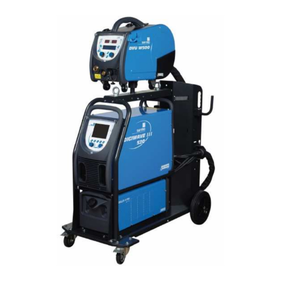
1 - GENERAL INFORMATION 1.1. PRESENTATION OF INSTALLATION DIGIWAVE III is a manual welding set that enables : MIG-MAG welding Feeding different types of wire Steel, stainless steel, aluminum and special wires Solid and cored wires Diameters from 0.6-0.8-1.0-1.2-1.4-1.6mm coated electrode welding TIG welding ARC-AIR Gouging process, using the torch for gouging: ARC AIR. - Page 5 WARNING : The plastic handles are not intended for slinging the set. Stability of the equipment is guaranteed only for an incline of maximum 10°. DIGIWAVE III...
-
Page 6: Power Sources Technical Specifications
1.3.POWER SOURCES TECHNICAL SPECIFICATIONS DIGIWAVE III 420 DIGIWAVE III 520 W000384989 W000384990 Primary side Primary power supply 400 V 400 V Primary power supply frequency 50/60Hz 50/60Hz Effective primary consumption 21.1 A 28,5 A Maximum primary consumption 27,1 A 33,9 A Fuse primary 25 A Gg 32 A Gg... -
Page 7: Starting Up
2 - STARTING UP 2.1. ELECTRICAL CONNECTIONS TO THE MAINS DIGIWAVE III is a 400 V 3-phase welding set. If your mains supply corresponds to requirements, connect the "three-phase + ground" plug to the end of the power cable. WARNING : Provided that the public low voltage system impedance at the point of common coupling is lower than : 98,2 m9 for the DIGIWAVE III 420 20,6 m9 or the DIGIWAVE III 520... -
Page 8: Starting Up
2.5. STARTING UP The main switch is located at the rear of the generator. Flip this switch to turn the machine on. This switch must never be flipped during welding. At each start-up, the generator displays the software version, the power and the connected optional device, as relevant of the power source. -
Page 9: Easy Starting-Up
3 - EASY STARTING-UP To ensure an optimal use of the installation and a good understanding of the following Instructions for use, we recommend you read the Wire Feeder operating manual first. 3.1. FRONT PANEL FUNCTIONS FIRST CONFIGURATION OF THE HUMAN-MACHINE INTERFACE (HMI) The human-machine interface (HMI) is located on the front panel of the power source: Validation Escape button to cancel the operations in progress or go back to the previous menu or page... - Page 10 The homepage contains 8 Main Menus : TIG LIFT Traceability Configuration MIG/MAG Maintenance Welding Programs User Synergy HMI CONFIGURATION STEPS For the first use of the power source, you must do the 4 following steps. STEP 1 Choice of the interface language Language selection Validation of the selection Position...
-
Page 11: First Setting For Easy Access To Weld
STEP 3 : Name of the power source. This is the name used for identifying the machine when installations communicate. Please check that different installation have different names. During an export to an external storage device, the name of the directory created is composed of the power source name and the date. - Page 12 Synergy bar + Trigger Mode ALW Data base Synergies / User Synergies Choice of metal Choice of wire diameter Welding cycle representation Choice of gas Indicative welding values Choice of the arc transfer Main welding parameters Choice of the working mode Choice of the trigger mode SYNERGY BASE MODE SETTING AND TRIGGER MODE Synergies...
- Page 13 Pre-gas Slows wire forwarding Welding step Crater fill Post-gas : Trigger pressed/ released : Wire speed Description The welder holds the trigger during the whole welding. Pressing the trigger will launch the welding (the beginning of the pregas), and releasing the trigger will stop the welding (beginning of crater filling).
- Page 14 WIRE SPEED MANUAL mode: By placing the cursor on SPEED WIRELESS, pressing OK shows the parameters together to facilitate the adjustment of parameters. Setting Mode Unit Interval step Depending of The wire speed varies in a range settled by the synergy. m/mn synergy The wire speed is not limited by the synergy table.
- Page 15 MIG WELDING PAGE you are allowed to weld only if the color of the top left icon is green Arc current measure Arc voltage measure Wirespeed Motor current of the wire feeder Welding time (includes all the steps of the welding cycle) The motor current of the wire feeder is proportional to the motor torque.
-
Page 16: Advanced Functionnalities Of Digiwave Iii
4 - ADVANCED FUNCTIONNALITIES OF DIGIWAVE III 4.1. MIG-MAG WELDING CYCLE ADVANCED SETTING MIG-MAG WELDING CYCLE SETTING The MIG welding cycle setting menu distinguishes 7 phases on the welding cycle: Pregas Hotstart Welding step Crater filler Burn back Affûtage fil Postgas WARNING the voltage is present at the end of the wire from the slow wire forwarding phase to the post retract spray phase. - Page 17 Softstart The softstart phase can be pre-set for the start of the weld, allowing a limited wire speed with low energy. Variables : Temps de palier : T(s) [0.00 ; 10.00] Temps de transitions : T(s) [0.00 ; 10.00] Paramètres principaux de soudage du palier de Hostart/Softstart. Note: If the setting exceeds the capacity of the source, the curve appears red Remark: With the SYN mode, the wire speed of the Hotstart / Softstart step is tuned relatively to the wire speed of the welding step (∆...
- Page 18 4. Craterfiller The crater fill phase allows filling up of the crater at the end of the weld for a good finish of welding. It is made by decreasing the arc regime at the end of the weld (downslope), then maintaining a low level of the wire speed for a defined timing (Craterfiller step).
- Page 19 FULL MIG-MAG WELDING CYCLE Pre-gas Slow wire inch [forward] Hotstart Welding phase Crater filler Burnback Affûtage fil Post-gas STRIKING ADJUSTMENT The striking adjustment is accessible in the menu SETUP of the MIG page. Note: the striking is the 2 phase of the welding cycle. The striking of every synergy is by default optimal in most of the application cases.
- Page 20 USER SYNERGIES The User Synergies Menu is accessible from the homepage. This function of the power source allows the user to create their own synergies from the existing ones. From the synergy bar, located on the top of the screen as in the MIG menu, choose an existing synergy by selecting the following parameters: metal, diameter, gas, arc transfer.
-
Page 21: Mig Welding Cycle Advanced Setting
The new synergic curve (in red) is different from the former one thanks to the chosen settings. The third step is the saving of the User Synergy. The power source allows the creation of up to 50 User Synergies. Make sure all of the fields are filled in order to easily find the references and using conditions of the User Synergy created. - Page 22 Create a program To create a program, press on and select “Create program” then press on OK Select the number of the created program Then call the program (if necessary, see step 3 of the first HMI configuration) You cannot create a program in these three different cases: If a program list is activated.
-
Page 23: Selection And Gestion Des Programmes De Soudage
4.3. SELECTION AND GESTION DES PROGRAMMES DE SOUDAGE This page is accessible from the homepage, it gives an overview of the available programs (except masked programs). To load a program from this page, select the program and press OK. Program Management MIG 4T Program Lists Program Lists Preview of selected program... - Page 24 MIG 4T PROGRAMS MANAGEMENT MIG 4T Program list is a particular case of the program list in which the programs MIG 4T are chainable during welding because they are compatible: same synergy (metal, wire diameter and gas). MIG 4T Program lists allow optimizing complex welds by adapting every specific operating condition of the cordon to a particular welding program. The transition can be done without stopping the welding, as in automatic N1, improving the productivity.
- Page 25 List management Program lists set into the power source Number of the list Program Lists Name of the list Welding programs contained into the list Activate or desactivate a list Add a new list Suppress an existing list See below useful icons for list management. Program List MIG 4T Program List Program...
-
Page 26: Import / Export Of Welding Programs
4.4. IMPORT / EXPORT OF WELDING PROGRAMS The export of welding programs can be useful to import those programs on another welding post, or to conserve a back up of those programs on an external storage medium. An exported program is associated to its number among the 100 available numbers. If a program is linked to a user synergy, this synergy will be automatically exported and imported with this program. - Page 27 The level of rights available are the following, in decreasing order: Administrator Technician Welder To be allowed to access to a function of the power source, the user must have a level higher or equad level of rights superior or equal to the level of rights access associated to the function.
-
Page 28: Program Limitations
4.6. PROGRAM LIMITATIONS The Limitations page is accessible from the SETUP of the MIG welding tuning page. USE: Program tuning gap limitation. Tuning limitation concerns the main parameters of the welding step of the current program: Wire speed Arc length Fine tuning To activate the limitation, turn the encoder The selected value gives a ‘window’... -
Page 29: Control Process
4.7. CONTROL PROCESS The Control Process allows improving the control of the welding variables. Indeed, the DIGIWAVE III is able to alert the user that the value of one of the following variables is out of a control corridor: Current welding Current of the wirefeeder motor (gives an idea of the wire speed) Arc tension The control corridor is defined by an upper threshold and a lower threshold that the user can tune for each variable. - Page 30 TRACEABILITY The traceability menu , accessible from the homepage, is divided in two parts: Configuration It allows activating export of welding characteristics by configuring the export delay after welding. T(s) [1: 100] Selecting the Welding trace adds extra parameters to the report. Two export choices are possible: USB –...
-
Page 31: Tig & Mma Welding
5 - TIG & MMA WELDING DIGIWAVE III is a multi-process welding post and as such, it allows welding in TIG and MMA. TIG LIFT In this mode, the user must use the TIG adaptor ref. W000379466 supplied for this use. You must use the ‘SCRATCH START’... -
Page 32: Detailed Installation
6 - DETAILED INSTALLATION 6.1. GONFIGURATION OF COOLING UNIT The MIG welding torch is connected to the front of the wire feeder, after ensuring it has been properly outfitted with the wear parts corresponding to the wire used for welding. Refer to the torch instructions. If you use a water-cooled torch, make sure to connect your cooling unit to the rear of the power source, as well as to the water harness. -
Page 33: Automation Interface Decription
Reverse the signal failure of the cooling unit. Normally Open or Normally Closed. (si défaut Input level of default actif) Manual commands Setting of the default wire speed by pressing the manual wire advance speed button on the Manual wire advance speed(m/min) Wire Feeder. - Page 34 Automation cycle configuration In the MIG menu, the specific auto "SETUP" page allows you to set: • Level of RI threshold (range: A) ; • Broken arc detection (range: s) ; • Delay before movement start (range: s) ; • Delay before movement stop (range: s) ;...
-
Page 35: External Communications
Pre-gas Slows wire forwarding Softstart Hotstart Welding 6/7/8 Craterfiller Burnback Postgas 6.3. EXTERNAL COMMUNICATIONS Communication with a USB key is possible as soon as a USB key is detected by the power source. Communication with remote host via Ethernet connection is possible: If the power source is equipped with IP address. - Page 36 The import/export of the Installation Backup is available in the menu: Maintenance > Installation Backup Backup of the Installation to: Installation Backup Restore it later on this power source or another power source Keep it for traceability reasons The power source is displayed on the left column and the external storage medium is displayed on the right column: Export Import Power source...
-
Page 37: Maintenance Of Installation
7 - MAINTENANCE OF INSTALLATION SOFTWARE UPDATE This page is accessible in the menu Maintenance . It allows updating software with a file from a USB key. This file is provided by Air Liquide Welding to improve the power source functions. The user must chose the file on the USB key then launch loading by pressing on the transfer button. The software version of every part of the installation can be identified in the page: Software identification. -
Page 38: Options
8 - OPTIONS 8.1. UNIT COOLER, REF. W000273516 8.2. WIRE FEEDER DVU W500, REF. W000372327 8.3. REMOTE CONTROL RC JOB II, REF. W000371925 Remote control functions: Setting the parameter settings (wire speed, fine setting, peak voltage, arc voltage and dynamism) according to the setting configuration, during welding and out of welding. -
Page 39: Workshop Trolley Ii, Ref. W000279927
8.5. WORKSHOP TROLLEY II, REF. W000279927 To move easily the power source in a workshop environment. 8.6. DUST FILTER, REF. W000373703 8.7. RC JOB II PLUG ON THE GENERATOR, REF. W000374008 8.8. TUBE HANDLE, REF. W000279930 8.9. PUSH PULL CARD OPTION, REF. W000275907 8.10. -
Page 40: Harnesses
8.15. HARNESSES AIR harness 2 M – 70 MM ref. W000275894 AIR harness 5 M – 70 MM ref. W000275895 AIR harness 10 M – 70 MM ref. W000275896 AIR harness 15 M – 70 MM ref. W000275897 2 (in order) AIR harness 25 M –... -
Page 41: Maintenance
9 - MAINTENANCE 9.1. ENTRETIEN Twice a year, depending on the use of the device, inspect the following: cleanliness of the generator electrical and gas connections WARNING The clogging of the dust filter may lead to the decrease of the duty cycle of the generator. WARNING : TWICE A YEAR Compressed air blowing. -
Page 42: Spare Parts
9.4. SPARE PARTS Capots DIGIWAVE III... - Page 43 Composants internes et onduleur : DIGIWAVE III...
- Page 44 DIGIWAVE III...
-
Page 45: Fault List Description
9.5. FAULT LIST DESCRIPTION The listed faults here after can be fixed by following the indications with caution. If a displayed fault doesn’t belong to this list below, please contact the after sales services. Servicing of electrical equipment must be performed by qualified personnel only. WARNING: Any intervention requiring the opening of the casing of the generator or one of its peripherals must be exclusively made by an agent appointed or authorized by Air Liquide Welding. - Page 46 DISPLAY OF THE MESSAGE E30 “Boot Failure” Only in AUTOMATIQUE mode time out of 3 seconds Effective Detecting the welding launch without striking DISPLAY OF THE MESSAGE E32 “Broken arc” Only in AUTOMATIQUE mode break detection arc DISPLAY OF THE MESSAGE E33 “Job problem” Calling a non existing program or unauthorized The program is not compatible with this software version Please update the software generator.
- Page 47 DISPLAY OF THE MESSAGE E83 « Detection Process U max control » Exceeded high threshold monitoring welding current user-defined DISPLAY OF THE MESSAGE E84 « Detection Process Control Reel I min» Exceeding low threshold current monitoring engine reeling user-defined DISPLAY OF THE MESSAGE E85 « Detection Process Control Reel Imax» Exceeded high threshold monitoring motor current reeling user-defined DISPLAY OF THE MESSAGE E86 «...
-
Page 48: Annex 1 - Synergies Tables
ANNEX 1 - SYNERGIES TABLES Angle à plat Easy Short Arc (ESA) Métal 0.6 0.8 0.9 1.0 1.2 1.4 1.6 Fil Massif Acier Ar 82 CO2 18 M21 ATAL 5 / ARCAL Force Ar 92 CO2 8 M20 ARCAL 21 / ARCAL Speed Ar 96 CO2 3 O2 M14 ARCAL 14 Fil Massif Inox (308L/316L) - Page 49 Alliage à base Nickel Type 625 ARCAL 1 / ARCAL Prime Ar 80 He 20 ARCAL 32 Fil Fourré à Poudre Métalique Acier Ar 82 CO2 18 M21 ATAL 5 / ARCAL Force Fil Fourré Basique Acier Ar 82 CO2 18 M21 ATAL 5 / ARCAL Force Ar 96 CO2 3 O2 Galvanisé...
- Page 50 ARCAL 12 / ARCAL Ar 98 CO2 2 Chrome Ar 81 He 18 CO2 M12 ARCAL 121 Fil Massif Acier Inoxidable à 17% Cr Ar 92 CO2 8 M20 ARCAL 21 / ARCAL Speed Ar 98 O2 2 M13 CARGAL 22 Speed Short Arc (SSA) Métal 0.6 0.8 0.9 1.0 1.2 1.4 1.6...
-
Page 51: Annex 2 - Specific Mig/Mag Welding Cycle
ANNEX 2 - SPECIFIC MIG/MAG WELDING CYCLE Application Strong Point Benefits All positions Universal for all positions Short Arc All materials Packing Suitable for all positions Universal for all positions Easy Short Arc All materials No globular area Suitable for all positions Extends the area of behavior Short Arc Acier Fast forward speed... -
Page 52: Annex 3 - Symbols
ANNEX 3 - SYMBOLS Signification Symbols for USB key connection Remote control connection Ethernet Connection Minus output power connection plus output power connection Power source connexion if automation level 1 is activated (RI) Cooler unit W000275516 Connection Warning, possible presence of hazardous voltage, do not touch. -
Page 53: Electrical Schemes
ELECTRICAL SCHEMES DIGIWAVE III 420 DIGIWAVE III... - Page 54 DIGIWAVE III 520...