Table of Contents
Instruction Manual
Form 5755
September 2005
Design D4 Control Valve Assembly
Contents
. . . . . . . . . . . . . . . . . . . . . . . . . . . . . . .
. . . . . . . . . . . . . . . . . . . . . . . . .
. . . . . . . . . . . . . . . . . . . . . . . . . . . . . .
. . . . . . . . . . . . . . . . . . . . . . . . . . . .
. . . . . . . . . . . . . . . . . . . . . . . . . . . . . . . .
. . . . . . . . . . . . . . . . . . . . . . . . .
. . . . . . . . . . . . . . . . . . . . . . . . . . . . . .
. . . . . . . . . . . . . . . . . . . . . . . . . . . .
. . . . . . . . . . . . . . . . . . . . . . . . . . . . . . . . .
. . . . . . . . . . . . . . . . . . . . . . . . . . . .
. . . . . . . . . . . . . . . . . . . . . . . . . . . . . . .
. . . . . . . . . . . . . . . . . . . . . . . . . . . . . . . .
Introduction
Scope of Manual
This instruction manual provides installation,
maintenance, and parts information for the Design
D4 control valve.
No person may install, operate, or maintain a Design
D4 control valve without first D being fully trained
and qualified in valve, actuator, and accessory
installation, operation, and maintenance, and D
carefully reading and understanding the contents of
this manual. If you have any questions about these
instructions, contact your Fisherr sales office before
proceeding.
Neither Emersonr, Emerson Process
Management, Fisher, nor any of their
affiliated entities assumes
responsibility for the selection, use
and maintenance of any product.
Responsibility for the selection, use,
and maintenance of any product
remains with the purchaser and
end-user.
www.Fisher.com
. . . . . . . . . . . . . . . . . .
Note
1
1
1
1
3
5
5
6
7
8
10
10
11
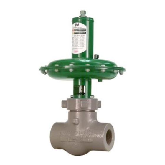
W8531/IL
Figure 1. Design D4 Control Valve
Description
The Design D4 control valve is a compact, rugged
valve designed primarily for high-pressure throttling
applications. This valve is ideal for use on pressure
and flow control applications within the oil and gas
production industry. The Design D4 valve also
makes an excellent dump valve for high-pressure
separators and scrubbers.
Specifications
Table 1 lists specifications for the Design D4 control
valve. Some of the specifications for a given control
valve as it originally comes from the factory are
stamped on a nameplate located on the actuator
spring barrel.
D4 Valve
Table of Contents

Related Manuals for Emerson FISHER D4


Summary of Contents for Emerson FISHER D4
-
Page 1: Table Of Contents
Fisherr sales office before makes an excellent dump valve for high-pressure proceeding. separators and scrubbers. Note Neither Emersonr, Emerson Process Management, Fisher, nor any of their Specifications affiliated entities assumes responsibility for the selection, use and maintenance of any product. - Page 2 Instruction Manual Form 5755 D4 Valve September 2005 Table 1. Specifications Available Configurations Material Temperature Capabilities Spring-to-Close Actuator Assembly: –40 to 93°C (–40 to 200°F) Spring-to-Open Valve Body Assembly: Standard Bonnet O-Ring: –46 to 149°C (–50 to Valve Body Sizes and End Connection Styles 300°F) Optional Fluoroelastomer Bonnet O-Ring: –23 to See table 2...
-
Page 3: Installation
Instruction Manual Form 5755 D4 Valve September 2005 Table 3. Maximum Shutoff Pressure Drops for Design D4 Control Valves (Spring-to-Close) When Used with Typical Control Instrumentation INPUT SIGNAL TO 0 to 1.2 Bar 0 to 1.4 Bar 0 to 2.0 Bar 0 to 2.3 Bar 0 to 2.4 Bar 0 to 3.4 Bar... - Page 4 Instruction Manual Form 5755 D4 Valve September 2005 Table 5. Maximum Shutoff Pressure Drops for Design D4 Control Valves (Spring-to-Open) When Used with Typical Control Instrumentation INPUT SIGNAL TO 0 to 1.2 Bar 0 to 1.4 Bar 0 to 2.0 Bar 0 to 2.3 Bar 0 to 2.4 Bar 0 to 3.4 Bar...
-
Page 5: Spring Adjustment
Instruction Manual Form 5755 D4 Valve September 2005 valves, use suitable gaskets between valve and 3. After adjustment, replace the spring case pipeline flanges. assembly (key 27). 5. If continuous operation is required during maintenance and inspection, install a conventional Maintenance three-valve bypass around the valve. -
Page 6: Valve Plug And Seat Ring
Instruction Manual Form 5755 D4 Valve September 2005 Valve Plug and Seat Ring downward movement of the stem is not restricted by instrument linkages attached to the stem (key 47). The Design D4 control valve is designed to allow Table 7. Torque for Seat Ring (Key 3) easy access to the valve plug and seat ring without VALVE SIZE RECOMMENDED TORQUE... -
Page 7: Valve Packing
Instruction Manual Form 5755 D4 Valve September 2005 BELLEVILLE SPRINGS REASONABLY BELLEVILLE SPRINGS FINGER TIGHT, THEN TIGHT TO SEAT THE PACKING TIGHTEN 5/6 TURN (5 FLATS ON THE RETAINER) E0862 Figure 2. Design D4 Belleville Spring Procedure adjustable wrench until the nut stops turning. A few surface condition is damaged, and cannot be hammer blows will be required to ensure that the improved by light sanding, replace the bonnet by... -
Page 8: Actuator
Instruction Manual Form 5755 D4 Valve September 2005 Actuator (Spring-to-Close) burrs or sharp edges on any threads or surfaces that might cut or damage an O-ring, bushing, the packing, or the diaphragm. When replacing O-rings WARNING and bushings, be sure the O-ring or bushing groove is clean and undamaged. - Page 9 Instruction Manual Form 5755 D4 Valve September 2005 6. Inspect the diaphragm and the actuator O-ring for CAUTION damage or deterioration, and replace if necessary. If the diaphragm is replaced, a new O-ring should also be installed. Over-tightening the diaphragm casing cap screws and nuts (keys 45 and 46) 7.
-
Page 10: Parts Ordering
5. Screw the adjusting stem (key 31) onto the stem (key 47) and secure the cotter pin (key 36). Make Neither Emerson, Emerson Process sure the bushing and O-ring are in place in the upper Management, Fisher, nor any of their casing. -
Page 11: Parts List
Instruction Manual Form 5755 D4 Valve September 2005 Parts List Description Part Number 2-inch valve Description Part Number 0.25 inch port diameter GE07389X012 0.375 inch port diameter GE07394X012 Valve Body 0.5 inch port diameter GE07397X012 0.75 inch port diameter GE07398X012 Valve Plug S41000 / S41600 HT 1-inch port diameter... - Page 12 Instruction Manual Form 5755 D4 Valve September 2005 GE02332-A Figure 3. Design D4 Valve Assembly (Spring-to-Close)
- Page 13 Instruction Manual Form 5755 D4 Valve September 2005 2 PLACES GE02334-B Figure 4. Design D4 Valve Assembly (Spring-to-Open)
- Page 14 Instruction Manual Form 5755 D4 Valve September 2005...
- Page 15 Instruction Manual Form 5755 D4 Valve September 2005...
- Page 16 Micro-Form and Fisher are marks owned by Fisher Controls International LLC, a member of the Emerson Process Management business division of Emerson Electric Co. Emerson and the Emerson logo are trademarks and service marks of Emerson Electric Co. All other marks are the property of their respective owners.