
Related Manuals for SainSmart Genmitsu


Summary of Contents for SainSmart Genmitsu
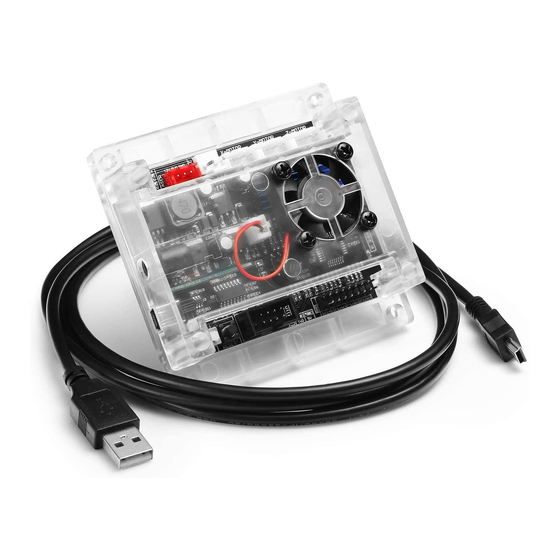
- Page 1 SainSmart Genmitsu Controller Board (GRBL) with ABS case and built-in fan for Genmtisu CNC Router 3018, 3018-PRO, 1810-PRO User Manual V1.0 Jun 2020...
-
Page 2: Preface
Genmitsu 1810-PRO, 3018 and 3018-PRO CNC milling/engraving machines. It is also compatible with our blue SainSmart laser module. In general, it can also be used with other 3018 series CNC machines and laser modules of other manufacturers. For understandable reasons, however, we cannot guarantee this. -
Page 3: Table Of Contents
Table of Content Topic Page Preface Table of Content 1 – Parts List 2 – Control Module Design 3 – Setting V 4 – Assembly and Operation 5 – Update Firmware 6 – Optional Accessories... -
Page 4: Parts List
1 – Parts List GRBL Controller USB cable (USB-A <-> mini-USB) -
Page 5: Control Module Design
2 – Control Module Design The control module measures just 91mm x 87mm x 23mm. It has a very quiet, brushless fan which provides sufficient cooling for the three A4988 stepper motor drivers, which have a common aluminium heat sink. Each of these 3 stepper motor drivers can deliver a motor current of up to 2A at 12V. - Page 6 2 – Control Module Design Connection for 24V spindle motor The connection for the 24VDC spindle motor is controlled by an IRF024 N-channel MOSFET with a maximum load of 10A. Since the MOSFET is not cooled, the maximum load capacity should not be used. However, this is still quite sufficient to operate a 775ER type motor.
- Page 7 2 – Control Module Design Connection for Stepper Motors The module comes with 4-pin connectors for 3 stepper Motors. One for the X-, one for the Y- and another one for the Z-axis. The pin assignment is as follows. Pin assignment: PCB edge XH 2.54 type 4-wire...
- Page 8 2 – Control Module Design Connection for external 24V power supply unit On the left side of the control board there is a DC Power jack for connecting an external 24VDC power supply.The outer ring is connected to GND whilst the inner pin is connected to +24V.
- Page 9 2 – Control Module Design Connection for offline-controller An external offline-controller can be connected to the 8-pin tub connector. This makes it possible to operate the CNC milling/engraving machine connected to the control module independently without an additional PC. In such a case, the positioning data (g-code) are stored beforehand on a micro-SD card located in the offline-controller.
- Page 10 2 – Control Module Design Connection for limit switches and Z-Probe Limit switches as well as a measuring device for the Z-axis (Z-probe) can be connected via the 16-pin plug that is also available at the bottom edge of the control module. Pin assignment: Z-lim Z-lim...
- Page 11 2 – Control Module Design Connection of limit switches For each of the 3 axes there are connections for two limit switches on the control module. The connections of the limit switches of one axis are connected parallel to each other. The direction of movement enables the control module to differentiate which limit switch was triggered.
- Page 12 2 – Control Module Design ICSP interface On the right side of the board there are 6 pads for the ICSP interface (in-circuit serial programming). They have been setup in a 1.27mm grid. Since a bootloader is already preinstalled on the ATMEGA328P at the factory, this interface is normally no longer required for later operation of the control board.
-
Page 13: Setting
3 – Setting V Setting V Before connecting stepper motors to the control module, the maximum motor currents for the stepper motors used must first be set on the control module using the appropriate miniature potentiometers. For the stepper motor drivers of the type A4988 used in the control module, the formula for determining the maximum motor current is: (maximum motor current) = V / (8 x R... -
Page 14: Assembly And Operation
4 – Assembly and Operation Assembly Please refer to the manual of your milling / engraving machine for assembly instructions. Pay attention to the required cable lengths of the supply lines to all movable elements. If possible, use additional fabric hoses to protect the supply lines. - Page 15 4 – Assembly and Operation A PWM laser module, such as the blue SainSmart 5500MW laser module, can be connected to the red 3-pin connector labeled "LASER" using the 3-core cable supplied with the laser module. Note that either a spindle motor is connected to the "SPINDLE" connector or a laser module is connected to the "LASER"...
-
Page 16: Update Firmware
Internet by searching for "xloader arduino". Hint: SainSmart is not liable for damage to the control module or other modules and devices connected to it resulting from improper or incorrect firmware installation. SainSmart is also not liable for any other damage to persons or property. - Page 17 5 – Update Firmware Installing the firmware Connect the control module to a Windows PC with USB connection. The USB port of the PC supplies the microprocessor of the control module with sufficient voltage. Therefore, make sure that the CNC controller's external power supply is disconnected or switched off.
- Page 18 5 – Update Firmware In Device Manager, locate the "Ports (COM & LPT)" entry and click it to display the active driver that is in use. For this CNC control boards, it should be "CH340", but it may display different COM port numbers. Make a note of the COM port number as it will be needed later.
- Page 19 5 – Update Firmware Double-click the highlighted driver line to expand it. When expanded, will display multiple tabs, click the Port Settings tab and set it to transfer at 115200 bits per second.
- Page 20 5 – Update Firmware Use the file manager to navigate to the directory where you saved the update file and unpack it. In the created file there is usually also an executable program called "XLoader". Double-click on this program to start it and ignore any error messages that may appear.
-
Page 21: Optional Accessories
6 – Optional Accessories 5.5W Engraving CNC milling cutter, Laser module material Milling chuck Accessories for your milling/engraving machine are best purchased from SainSmart:... - Page 22 Copyright © 2020 by SainSmart All rights reserved. This manual or any portion thereof may not be reproduced or used in any manner whatsoever without the written permission of the publisher, except for the use of brief quotations embodied in critical reviews and certain other noncommercial uses permitted by copyright law.