
Related Manuals for GE Mark VIeS


Summary of Contents for GE Mark VIeS
- Page 1 GEH-6855_Vol_II Mark* VIeS Functional Safety Systems for General Market Volume II: System Guide for General-purpose Applications July 2019 Public Information...
- Page 2 It is understood that GE may make changes, modifications, or improvements to the equipment referenced herein or to the document itself at any time. This document is intended for trained personnel familiar with the GE products referenced herein.
- Page 3 Related Documents Doc # Title GEH-6855_Vol_I Mark VIeS Functional Safety Systems for General Market Volume I: System Guide Mark VIeS Control General Market Functional Safety Manual GEH-6860 Mark VIeS Functional Safety System Equipment in Hazardous Locations (HazLoc) GEH-6861 Instruction Guide...
- Page 4 Indicates a procedure or condition that, if not strictly observed, could result in damage to or destruction of equipment. Caution Indicates a procedure or condition that should be strictly followed to improve these applications. Attention GEH-6855_Vol_II GEH-6855_Vol_II Mark VIeS Functional Safety Systems Volume II Public Information...
- Page 5 Control System Warnings To prevent personal injury or damage to equipment, follow all equipment safety procedures, Lockout Tagout (LOTO), and site safety procedures as indicated by Employee Health and Safety (EHS) guidelines. Warning This equipment contains a potential hazard of electric shock, burn, or death. Only personnel who are adequately trained and thoroughly familiar with the equipment and the instructions should install, operate, or maintain this equipment.
- Page 6 3.4 IONet Switch Specifications ........................87 3.5 Operation ............................. 88 3.6 Third-party Switch Replacement....................... 90 4 YAIC Analog I/O Modules ......................91 4.1 Mark VIeS YAIC Analog I/O Pack......................91 4.2 YAIC Specific Alarms ...........................101 4.3 TBAIS1C Analog Input/Output .......................106 4.4 STAIS2A Simplex Analog Input......................113 5 YDIA Discrete Input Modules ....................
- Page 7 7.16 SUAA Universal Analog Terminal Board ....................225 8 YVIB Vibration Monitor Modules ....................227 8.1 Mechanical Vibration Standards ......................227 8.2 Mark VIeS YVIB Vibration Monitor I/O Pack....................228 8.3 YVIB Functions ...........................234 8.4 YVIB Specific Diagnostic Alarms ......................271 8.5 TVBA Vibration Input ...........................276 9 PSCA Modbus Master (Serial Communication) Module.............285...
- Page 8 Notes GEH-6855_Vol_II GEH-6855_Vol_II Mark VIeS Functional Safety Systems Volume II Public Information...
- Page 9 Orderable Part Numbers The following tables provide the orderable part numbers for the Mark VIeS Functional Safety System product components, including I/O packs, modules, Terminal Boards (TB), and daughterboards. Note For replacement and ordering instructions, refer to the sections Replacement Ordering Parts.
- Page 10 Cover: 151X1202YE08PP16BL TMR, 24 pt - 48 V dc Contact In, 24 pt TB (1-24): 173C9123BB IS410TBCIS3C 4" T-type TB, with cover and TB blocks 24 pt TB (25-48): 173C9123BB GEH-6855_Vol_II GEH-6855_Vol_II Mark VIeS Functional Safety Systems Volume II Public Information...
- Page 11 Module Part Numbers (continued) Associated Base Replacement Part within I/O Pack/Part Description Notes Assembly/Accessory Number Module Board: IS400BPPCS1A Contact Output Safety I/O pack Board: IS200BPDOS1 Simplex, 12 Form C Contact Out, Board: IS400SRLYS2A 7" S-type TB, with cover and TB Cover: 151X1202YE04PP05BL IS410SRLYS2A plugs...
- Page 12 Distribution module (24 or 48 V IS410JPDEG1A 7 A fuse: 64G5001-001 dc), with cover 15 A fuse: 64G5003-001 Control Power Fanout Board: IS400JPDHG1A IS410JPDHG1A Distribution, with cover Cover: 151X1202YE12PP03BL GEH-6855_Vol_II GEH-6855_Vol_II Mark VIeS Functional Safety Systems Volume II Public Information...
- Page 13 IS400TRLYS#F wetting and fusing, Add hi side fusing and UL Pending IS400WPDFH2A 3.15 A fuse: 64G5005-005 sensed power to 2 groups of 6 relays Mark VIe and Mark VIeS Controllers Part Numbers Associated Base I/O Pack/Part Replacement Part within Description Notes Assembly/Accessory...
- Page 14 DIN-rail Option DIN-rail base for ESWA, long edge of switch body 259B2451BVP2 perpendiculr to DIN-rail Option DIN-rail base for ESWB, long edge of switch body 259B2451BVP4 perpendicular to DIN-rail GEH-6855_Vol_II GEH-6855_Vol_II Mark VIeS Functional Safety Systems Volume II Public Information...
- Page 15 Mark VIe Power Supplies and OR-ing Module Part Numbers Replacement Associated Base I/O Pack/Part Description Part within Notes Assembly/Accessory Number Module 120W Power Supply 342A3648P120W24 120/240AC//125/250DC > 24DC 120W Power Supply 342A3648P120W24C 120/240AC//125/250DC > 24DC, Coated 120W Power Supply 342A3648P120W28 120/240AC//125/250DC >...
- Page 16 Notes GEH-6855_Vol_II GEH-6855_Vol_II Mark VIeS Functional Safety Systems Volume II Public Information...
- Page 17 Note For additional information, refer to the following documents: • Mark* VIe and Mark VIeS Functional Safety UCSC Controller Summary Sheet (GEI-100867) • Mark VIeS Functional Safety Systems for General Market Volume I: System Guide (GEH-6855_Vol_I) • ToolboxST *User Guide for Mark VIeS Functional Safety Systems (GEH-6862) •...
- Page 18 The UCSCH1B is available beginning with ControlST* V07.01, and supports Simplex, Dual, and Triple Modular Redundant (TMR) redundancy. UCSCH1 Platform Configuration Supported Features Platform Embedded PPNG Embedded EtherCAT ✓ UCSCH1B Mark VIe UCSCH1B Controller GEH-6855_Vol_II GEH-6855_Vol_II Mark VIeS Functional Safety Systems Volume II Public Information...
- Page 19 2.1.2 Mark VIeS UCSCS2A Controllers The IS420UCSCS2A dual core controller runs the Mark VIeS Safety control applications used for functional safety loops to achieve SIL 2 and 3 capabilities. Mark VIeS Safety equipment is used by operators that are knowledgeable in safety-instrumented system (SIS) applications to reduce risk in critical safety functions.
- Page 20 IS420UCSCH1: 4 GB DDR3-1333 SDRAM Memory IS420UCSCS2: 2 GB DDR3-1066 SDRAM Supports 3067 nonvolatile program variable, 338 forces, and 64 totalizers NVSRAM Not supported by the Mark VIeS Safety control • 5 Ethernet ports on front panel (Refer to the section Interface Details.) •...
- Page 21 2.1.4 UCSC Mounting and Installation Requirements 2.1.4.1 UCSC Mounting Requirements The following are requirements for mounting the UCSC controller: • Directly mount the UCSC to the mounting base using the two mounting screws. • Vertical mount with unobstructed air flow through fins. •...
- Page 22 UCSC Mounting Requirements to Achieve 70ºC Operating Temperature GEH-6855_Vol_II GEH-6855_Vol_II Mark VIeS Functional Safety Systems Volume II Public Information...
- Page 23 UCSC Mounting Requirements to Achieve 65ºC Operating Temperature Controllers GEH-6855_Vol_II System Guide 23 Public Information...
- Page 24 UCSC Controller Mounting Dimensions GEH-6855_Vol_II GEH-6855_Vol_II Mark VIeS Functional Safety Systems Volume II Public Information...
- Page 25 2.1.4.2 Power Requirements Power Requirements Item Units UCSC Controller Input Power Watts — 30.8 Voltage V dc 24/28 Input Capacitance — — Non-replaceable 4 A 125 V dc rated fuse Surge Protection Nominal melting: 26 A squared seconds (A sec) Provided Reverse Polarity Protection Reversing the + and - input will not damage the UCSC, nor will it power up.
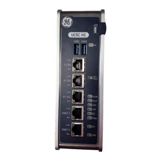
- Page 26 2.1.4.3 Interface Details UCSC Connection Ports (Front View) Note For further information, refer to the ToolboxST User Guide for Mark VIeS Functional Safety Systems (GEH-6862), the section System Controller Platforms. GEH-6855_Vol_II GEH-6855_Vol_II Mark VIeS Functional Safety Systems Volume II Public Information...
- Page 27 † For instructions to set up the controller Internet Protocol (IP) address using the COM port, refer to the ToolboxST User Guide for Mark VIeS Functional Safety Systems (GEH-6862), the section Configure and Transfer IP Address to UCSC Controller. Controllers...
- Page 28 TCP/IP protocol is used for alarm communication to HMIs. Interface to LAN Modbus TCP Slave EGD protocol is used for application variable communication to HMIs. Not supported ENET 2 GEH-6855_Vol_II GEH-6855_Vol_II Mark VIeS Functional Safety Systems Volume II Public Information...
- Page 29 From the ToolboxST Component Editor, select Device, Download, and Controller Setup to launch the Controller Setup Wizard. Follow the on-screen instructions to load the flash drive. Refer to the ToolboxST User Guide for Mark VIeS Functional Safety Systems (GEH-6862), the section Configure and Transfer IP Address to UCSC Controller for further instructions.
- Page 30 2.1.5.2 LEDs The locations and descriptions of the LED indicators that are located on the front panel of the UCSC controller and the UCEC module are as follows. GEH-6855_Vol_II GEH-6855_Vol_II Mark VIeS Functional Safety Systems Volume II Public Information...
- Page 31 Both of these warnings drive the OT LED and are annunciated as diagnostic alarms. 2.1.5.4 UCSC COM Port Typically used by GE to troubleshoot in the field, the UCSC COM port accepts a UCSC COM port adapter and a standard serial to USB cable is used to connect to another computer.
- Page 32 VM. Note To configure virtual network adapters, refer to the ToolboxST User Guide for Mark VIeS Functional Safety Systems (GEH-6862), the section Virtual Network Adapters. To configure the virtual network in the EFA, refer to the Field Agents User Guide (GFK-2993).
- Page 33 2.1.8 Agency Certifications and Standards Refer to the UCSC Installation and Maintenance Requirements (IMR) (GFK-3006) for conformance to these standards. Description Marking Comments ISA 12.12.01: 2015, Class I Div. 2 Groups ABCD, UL 60079-0 Ed 6.0 (2013), Class I, North America Safety for Zone 2 Gas Group ABCD, UL 60079-15 Edition 4.0 (2013), [Ex nA] Programmable Controller for use in Hazardous locations...
- Page 34 2.1.9 Accessories Part Number Description UCSB to UCSC Power Cable Adapter 121T8700P0002 UCSC COM Port Adapter (RJ-45 to DB9F) 121T6659P0001 GEH-6855_Vol_II GEH-6855_Vol_II Mark VIeS Functional Safety Systems Volume II Public Information...
- Page 35 2.1.10 UCSC Hardware Replacement Replacement parts may contain static-sensitive components. Therefore, GE ships replacement parts in anti-static bags. When handling electronics, make sure to store them in anti-static bags or boxes and use a grounding strap. To prevent component damage caused by static electricity, treat all boards with static-sensitive handling techniques.
- Page 36 15. Cycle power on the controller. 16. From the ToolboxST Controller Setup Wizard window, click Finish. 17. Perform a Download to bring the controller back online and in the controlling state. GEH-6855_Vol_II GEH-6855_Vol_II Mark VIeS Functional Safety Systems Volume II Public Information...
- Page 37 2.3 Shared IONet The Shared IONet function (with ControlST V04.06 or higher) enables the sharing of Mark VIeS Safety inputs with another basic process Mark VIe controller set, saving the cost of redundant sensors and I/O. Refer to the Mark Controllers Shared IONet User Guide (GEH-6812) for more information.
- Page 38 Click to go online. Wait and reset any alarms, if needed. Build and Download again, if needed. Wait and reset any alarms, if needed. Select the Component InfoView Status tab. GEH-6855_Vol_II GEH-6855_Vol_II Mark VIeS Functional Safety Systems Volume II Public Information...
- Page 39 The color of the Status tab indicates overall health and equality status of the controller, including its associated I/O hardware. A major difference in controller equality means that the configuration in the ToolboxST application is different from the controller configuration. •...
- Page 40 Build and download the configuration to the controller, wait for I/O pack communication status to change, then scan and download to the I/O pack. Note This alarm is not reported to the WorkstationST Alarm Viewer. This alarm is generated by the ToolboxST application, not by the firmware. GEH-6855_Vol_II GEH-6855_Vol_II Mark VIeS Functional Safety Systems Volume II Public Information...
- Page 41 Note This alarm is obsolete. Description Control/Status communication failure between [ ] and controller Possible Cause • Asynchronous Drive Language (ADL) communication unhealthy • Terminal board barcode typed incorrectly in the ToolboxST configuration • Wrong terminal board is configured in the ToolboxST application •...
- Page 42 Solution Rebuild the controller and download. Note This alarm is not reported to the WorkstationST Alarm Viewer. This alarm is generated by the ToolboxST application, not by the firmware. GEH-6855_Vol_II GEH-6855_Vol_II Mark VIeS Functional Safety Systems Volume II Public Information...
- Page 43 Description ToolboxST application cannot retrieve diagnostics information from I/O pack [ ] Possible Cause • Cannot get requested information from I/O pack or module • Communication program failure • I/O pack or module unable to retrieve IP address Terminal board Bar Code entered incorrectly in ToolboxST configuration •...
- Page 44 For an I/O module, perform the following: • From the ToolboxST application, rebuild the system, then download the application and configuration to the I/O module. • Replace the I/O module. GEH-6855_Vol_II GEH-6855_Vol_II Mark VIeS Functional Safety Systems Volume II Public Information...
- Page 45 Description Application Runtime Error - [ ] Frame skips occurred Possible Cause There is an overloaded processor or a processor malfunction. Frame number skips were detected. The frame number should incrementally increase during Controlling state. Solution For a controller, do the following: •...
- Page 46 • Reload firmware and application and restart. • If controller is a UCSA, try formatting and reloading the flash memory. • If this does not work, replace the controller. GEH-6855_Vol_II GEH-6855_Vol_II Mark VIeS Functional Safety Systems Volume II Public Information...
- Page 47 Description Application Error - application overrunning the frame Possible Cause Application cannot start within frame. Solution Check application loading and reduce the amount of application code or frequency of execution. Build application and download to all controllers. Description Controller CPU overtemperature, Temp [ ] °C, Threshold [ ] °C Possible Cause •...
- Page 48 Verify that all redundant controllers on the UDH network are receiving all expected EGD exchanges. • Verify that all relevant devices are powered on and producing data on the network. GEH-6855_Vol_II GEH-6855_Vol_II Mark VIeS Functional Safety Systems Volume II Public Information...
- Page 49 Description EGD Error - Fault Tolerant EGD data requested Possible Cause An EGD exchange timeout occurred on the requesting controller. Redundant processor (if applicable) unable to receive UDH EGD inputs and has requested that EGD data be transferred over the IONet. Solution •...
- Page 50 Check for a bad Ethernet cable to network switch. • Check for a bad network switch: − Place the Ethernet cable into empty port. − If the problem persists, replace the network switch. GEH-6855_Vol_II GEH-6855_Vol_II Mark VIeS Functional Safety Systems Volume II Public Information...
- Page 51 Description Startup sequence failed - Data initialization timeout R processor Possible Cause Controller unable to complete startup data initialization • IONet malfunction • Controllers have different application revisions • One or more controllers powered down • Controller overloaded by external command messages Solution •...
- Page 52 Frame number skips detected. Frame number should monotonically increase until rollover; alarm occurs following a single frame number skips in successive frames. Solution • Check IONet (switches, cables). • Replace the controller. GEH-6855_Vol_II GEH-6855_Vol_II Mark VIeS Functional Safety Systems Volume II Public Information...
- Page 53 Description Memory Verification Failed – Firmware Processes Possible Cause A modification has occurred in the code segment for one of the processes. This indicates that a hardware memory failure has occurred. Solution Replace the controller. Description Controller is Unlocked Possible Cause •...
- Page 54 • Replace Ethernet cable(s). • Replace the I/O pack. • Move the I/O pack’s Ethernet cable into an empty IONet switch port. If problem persists, replace the IONet switch. GEH-6855_Vol_II GEH-6855_Vol_II Mark VIeS Functional Safety Systems Volume II Public Information...
- Page 55 Description Memory Validation Failed – Blockware Data Structures Possible Cause A hardware memory failure because application process data was modified (data should not change after controller goes online) Solution Replace the controller. Description Memory Validation Failed – Configuration Shared Memory Possible Cause A hardware memory failure because system process data was modified (data should not change after controller goes online) Solution Replace the controller.
- Page 56 FAILURE control state. Solution • Ignore alarm if it occurs during a restart of the controller. • Replace the controller, if the alarm occurs during normal operation. GEH-6855_Vol_II GEH-6855_Vol_II Mark VIeS Functional Safety Systems Volume II Public Information...
- Page 57 Description Internal Runtime error - Sequencer frame state timeout out-of-bounds (±15%) Possible Cause Possible hardware malfunction. Sequencer frame state timeout greater than ±15% of nominal. Alarm occurs following a sequencer frame state timeout being out-of-bounds three frames in row; after five, controller put in FAILURE control state.
- Page 58 Possible Cause Network interface has been disabled to protect itself from excessive activity on the network. Solution • Check for network loops. • Monitor network activity and remove excessive traffic. GEH-6855_Vol_II GEH-6855_Vol_II Mark VIeS Functional Safety Systems Volume II Public Information...
- Page 59 Description Ethernet Interface [ ] disabled due to excessive traffic Possible Cause Network interface has been disabled to protect itself from excessive activity on the network Solution • Check for network loops. • Monitor network activity and remove excessive traffic. Description Ethernet Interface [ ] disabled due to excessive traffic Possible Cause Network interface has been disabled to protect itself from excessive activity on the network Solution...
- Page 60 Check for a defective network switch by placing the producer's Ethernet cable into an empty port. If the problem persists, replace the network switch. • Replace the producer processor module. GEH-6855_Vol_II GEH-6855_Vol_II Mark VIeS Functional Safety Systems Volume II Public Information...
- Page 61 Description Auto-Reconfiguration server installation is incomplete Possible Cause • A download from the ToolboxST application to an I/O pack and/or the Auto-Reconfiguration server has failed • Not all of the I/O packs were selected for download Solution Perform a scan and download using the ToolboxST application. Description Auto-Reconfiguration server failed scanning or downloading an I/O pack Possible Cause At least one I/O pack is in an unexpected state that the Auto-Reconfiguration server is unable to handle Solution...
- Page 62 A runtime malfunction has disabled the hardware watchdog protective function • A hardware failure has disabled the hardware watchdog protective function Solution • Reload firmware and restart. • If problem persists, replace hardware. GEH-6855_Vol_II GEH-6855_Vol_II Mark VIeS Functional Safety Systems Volume II Public Information...
- Page 63 Description CDH EGD fault detected by the R processor Possible Cause • CDH EGD producer is powered down • Producer is unhealthy • Ethernet connection(s) failure Solution • Ensure all EGD producers are powered up and healthy. • Check for a defective Ethernet cable from producer to network switch. Replace the cable(s). •...
- Page 64 Fan loss detected for controller fan [ ] Possible Cause • Hardware malfunction • Fan power not applied Solution • Check the fan. • Verify that the power connector is properly inserted. • Replace the fan. GEH-6855_Vol_II GEH-6855_Vol_II Mark VIeS Functional Safety Systems Volume II Public Information...
- Page 65 Reduce the content of the application configuration/code. • To address a memory leak, reboot the device to reinitialize baseline memory use. Monitor for reoccurrence and contact your GE representative. Description Syspage inconsistency detected Possible Cause Memory corruption Solution Restart the controller to re-initialize QNX syspage.
- Page 66 Reload firmware and parameters to the affected I/O module. • Reload firmware and application to all controllers. • If the problem persists, replace the affected I/O module, then replace the controller. GEH-6855_Vol_II GEH-6855_Vol_II Mark VIeS Functional Safety Systems Volume II Public Information...
- Page 67 Description S network shared I/O module inputs unhealthy Possible Cause • I/O module restarting or restarted • I/O module application/configuration missing • Application/configuration does not match in I/O module and controller • Failed Ethernet connection between I/O module and controller •...
- Page 68 Solution • Transition the controller from Secure to Open state then back to Secure to generate a new certificate and private key. • Contact the Certificate Authority (CA) Administrator. GEH-6855_Vol_II GEH-6855_Vol_II Mark VIeS Functional Safety Systems Volume II Public Information...
- Page 69 Description Controller certificate will expire within seven days Possible Cause Controller certificate will expire within seven days Solution • Transition the controller from Secure to Open state then back to Secure to generate a new certificate and private key. • Contact the Certificate Authority (CA) Administrator.
- Page 70 Solution Contact the CA Administrator. Description Certificate Authority (CA) certificate will expire within one day Possible Cause CA certificate will expire within one day Solution Contact the CA Administrator. GEH-6855_Vol_II GEH-6855_Vol_II Mark VIeS Functional Safety Systems Volume II Public Information...
- Page 71 Description Certificate Authority (CA) certificate has expired; controller is no longer in Secure state Possible Cause CA certificate has expired Solution Contact the CA Administrator. Description Certificate Revocation List (CRL) has expired Possible Cause CRL has expired Solution Contact the CA Administrator and request/confirm the renewal of the CRL. After the CRL is renewed, from the Mark VIe Device menu select View | Diagnostics | Controller Advanced Diagnostics.
- Page 72 Note It is the user’s responsibility to change the default password to a unique password. If you do not know the default password, contact the nearest GE Sales or Service Office, or an authorized GE Sales Representative. To change the controller password, refer to the ToolboxST User Guide for Mark VIeS Functional Safety Systems (GEH-6862), the section Controller Password Change.
- Page 73 1000-2024 Description Inputs unhealthy on IO Module [ ], R pack IONet [ ] - Message Timeout Possible Cause • I/O pack restarting or restarted • I/O pack application/configuration is missing • Application/configuration does not match in the I/O pack and controller •...
- Page 74 Check for faulty Ethernet cable from I/O pack to network switch and/or from switch to controller. Replace cable(s) if necessary. • Replace the I/O pack. • Defective network switch, place I/O pack's Ethernet cable into empty port. If problem persists, replace network switch. GEH-6855_Vol_II GEH-6855_Vol_II Mark VIeS Functional Safety Systems Volume II Public Information...
- Page 75 1000-2024 Description Inputs unhealthy on IO Module [ ], IONet [ ] - Message Timeout Possible Cause • I/O pack restarting or restarted • I/O pack application/configuration is missing • Application/configuration does not match in the I/O pack and controller •...
- Page 76 • Reload firmware and parameters to the affected I/O pack. • Reload firmware and application to all controllers. • If problem persists, replace affected I/O pack, then replace controller. GEH-6855_Vol_II GEH-6855_Vol_II Mark VIeS Functional Safety Systems Volume II Public Information...
- Page 77 1000-2024 Description Inputs unhealthy on IO Module [ ], S Pack IONet [ ] - Major Signature Mismatch Possible Cause Application/configuration does not match in the I/O pack and controller. Solution • Rebuild and download application/parameters to all controllers and I/O packs. •...
- Page 78 • Reload firmware and parameters to the affected I/O pack. • Reload firmware and application to all controllers. • If problem persists, replace affected I/O pack, then replace controller. GEH-6855_Vol_II GEH-6855_Vol_II Mark VIeS Functional Safety Systems Volume II Public Information...
- Page 79 1000-2024 Description Inputs unhealthy on IO Module [ ] IONet [ ] - Minor Signature Mismatch Possible Cause Application/configuration does not match in the I/O pack and controller. Solution • Rebuild and download application/parameters to all controllers and I/O packs. •...
- Page 80 • Reload firmware and parameters to the affected I/O pack. • Reload firmware and application to all controllers. • If problem persists, replace affected I/O pack, then replace controller. GEH-6855_Vol_II GEH-6855_Vol_II Mark VIeS Functional Safety Systems Volume II Public Information...
- Page 81 1000-2024 Description Immediate Attention Required: Fieldbus I/O Module [ ] Not Detected on IoNet [ ] Possible Cause Note: If this diagnostic is active, the module needs to be replaced immediately. If it is simplex, the devices under this PFFA have lost communication. If it is redundant and not replaced, and a controller on the remaining module's IONet goes down, then control is lost for all devices under the PFFA modules.
- Page 82 Solution Check the EtherCAT device configuration in the ENI file and EtherCAT Configuration Tool. 2407 Description EtherCAT Master in unexpected state Possible Cause Bus does not match ENI file. Solution Download a new ENI file or plug in all devices. GEH-6855_Vol_II GEH-6855_Vol_II Mark VIeS Functional Safety Systems Volume II Public Information...
- Page 83 2408 Description EtherCAT ENI file does not match bus configuration Possible Cause ENI File imported in ToolboxST does not match the discovered network. Solution • Verify ENI file matches the network connected to the Mark VIe controller. • Verify EtherCAT network is connected and intact. 2409 Description EtherCAT redundant Ethernet links crossed Possible Cause Main and Redundant Ethernet links are swapped on the controller.
- Page 84 Notes GEH-6855_Vol_II GEH-6855_Vol_II Mark VIeS Functional Safety Systems Volume II Public Information...
- Page 85 Unmanaged Ethernet Switches GE’s product line of industrial unmanaged Ethernet 10/100 switches, ESWA and ESW, are specifically designed to meet the needs of real-time industrial control solutions. To meet the requirements for speed and functionality, the following features are provided: •...
- Page 86 Note For system requirements, redundancy, and other related information, refer to the Mark VIe Industrial Ethernet / IONet Switches Summary Sheet (GEI-100869) and the Mark VIeS Functional Safety Systems for General Market Volume I: System Guide (GEH-6855_Vol_I), the chapter Ethernet Networks.
- Page 87 LC-type † Fiber Single Mode Fiber (SMF) requires the additional IR SFP single-mode transducer, GE part # 65G2100–008. † A port adapter is used if needing to interface an existing SC fiber termination to the LC fiber port. GE part # 336A5026P01 SC to LC adapter is required for multi-mode fiber (most common).
- Page 88 The switch supports store and forward architecture, providing high data confidence. Switch architecture The switch provides soft start capability that limits inrush current to less than 200% of the Inrush current normal operating current. GEH-6855_Vol_II GEH-6855_Vol_II Mark VIeS Functional Safety Systems Volume II Public Information...
- Page 89 • flashes yellow for activity at half duplex In certain conditions, an input voltage sag, known as a brownout, may cause the GE IS420ESWBH#_ (ESWB) I/O Network (IONet) switch to incorrectly reboot and fail to re-establish communication with the system. If the ESWB switch experiences a...
- Page 90 DIN-rail mounts. There are seven screw holes used on the existing switch to support panel mounting. The following drawing displays the pattern and dimensions for these holes. Holes to Support Panel Mounting GEH-6855_Vol_II GEH-6855_Vol_II Mark VIeS Functional Safety Systems Volume II Public Information...
- Page 91 YAIC Analog I/O Modules 4.1 Mark VIeS YAIC Analog I/O Pack The Analog I/O pack (IS420YAICS1B) provides the electrical interface between one or two I/O Ethernet networks and an analog I/O terminal board. The YAIC contains a common processor board and an acquisition board specific to the analog input function.
- Page 92 Attention To upgrade or replace the YAIC, refer to the following replacement procedures for specific instructions: • Replace Mark VIeS Safety I/O Pack with Same Hardware Form • Replace Mark VIeS Safety I/O Pack with Upgraded Hardware Form The YAIC I/O pack is compatible with the TBAISIC and STAIS2A terminal boards.
- Page 93 4.1.2 YAIC Installation ➢ ➢ To install a new YAIC I/O module into an existing Mark VIeS panel Securely mount the desired terminal board. Directly plug one YAIC I/O pack for simplex or three YAIC I/O packs for TMR into the terminal board connectors.
- Page 94 75.15 Hz. Voltage signal feedbacks from the analog output circuits and calibration voltages are also sensed by the YAIC analog input section. GEH-6855_Vol_II GEH-6855_Vol_II Mark VIeS Functional Safety Systems Volume II Public Information...
- Page 95 4.1.3.2 Analog Output Hardware The YAIC includes two 0-20 mA analog outputs capable of 18 V compliance running simplex or TMR. A 14-bit digital-to-analog converter (DAC) commands a current reference to the current regulator loop in the YAIC that senses current both in the YAIC pack and on the terminal board.
- Page 96 Ambient Rating for Enclosure Design -40 to 70°C (-40 to 158 °F) Technology Surface mount Note For further details, refer to the Mark VIeS Functional Safety Analog I/O Module Summary Sheet (GEI-100866). GEH-6855_Vol_II GEH-6855_Vol_II Mark VIeS Functional Safety Systems Volume II Public Information...
- Page 97 4.1.5 YAIC Diagnostics The YAIC performs the following self-diagnostic tests: • A power-up self-test that includes checks of RAM, flash memory, Ethernet ports, and most of the processor board hardware • Continuous monitoring of the internal power supplies for correct operation •...
- Page 98 4-20 mA input is less than the value of parameter Min_ MA_Input TMR_DiffLimt Diag limit, TMR input vote difference, in percent of (High_Value - 0 to 200 % Low_Value) GEH-6855_Vol_II GEH-6855_Vol_II Mark VIeS Functional Safety Systems Volume II Public Information...
- Page 99 4.1.6.3 Outputs Output Name Output Description Choices AnalogOutput01 - First of two analog outputs - board point, Point edit Output REAL AnalogOutput02 Output_MA Output current, mA selection. Unused, 0-20 mA PwrDownMode OutputState State of the outputs when offline. When the YAIC loses communication with the controller, this parameter determines HoldLastVal how it drives the outputs:...
- Page 100 Status of Suicide Relay for Output 1 Input BOOL OutSuicide2 Status of Suicide Relay for Output 2 Input BOOL Out1MA Feedback, Total Output Current, mA Input REAL Out2MA Feedback, Total Output Current, mA Input REAL GEH-6855_Vol_II GEH-6855_Vol_II Mark VIeS Functional Safety Systems Volume II Public Information...
- Page 101 4.2 YAIC Specific Alarms The following alarms are specific to the YAIC I/O pack. 32-41 Description Analog Input [ ] unhealthy Possible Cause • Excitation to transducer is wrong or missing. • Transducer is defective. • Analog input current/voltage input is beyond the specified range. •...
- Page 102 • Hardware failure causing one I/O pack to drive too much output current Solution • Verify that the value of TMR_SuicLimit is set correctly. • Replace the I/O pack. GEH-6855_Vol_II GEH-6855_Vol_II Mark VIeS Functional Safety Systems Volume II Public Information...
- Page 103 70-71 Description Output [ ] Total current varies from reference current Possible Cause The difference between the commanded output current and total feedback is greater than TMR_ SuicLimit. • Field wiring problem • Open-circuit on output or total loop resistance is too high •...
- Page 104 Possible Cause The time signal used to generate a dither on the valve output signal does not appear to being changing. This could cause a frozen valve. Solution • Cycle power to the I/O pack. • Replace the I/O pack. GEH-6855_Vol_II GEH-6855_Vol_II Mark VIeS Functional Safety Systems Volume II Public Information...
- Page 105 Description I/O pack internal reference voltage out of limits Possible Cause The calibration reference voltage for the analog inputs is more than ±5% from the expected value, indicating a hardware failure. Solution • Check the I/O pack ground quality through mounting bolts. •...
- Page 106 The TBAI has three DC-37 pin connectors for TMR I/O packs. Simplex I/O redundancy is also supported using a single JR1 connection. Note The TBAIS1C is IEC 61508 safety-certified when used with the Mark VIeS YAIC. J ports For simplex, connect I/O pack to JR1.
- Page 107 4.3.1 Installation Connect the input and output wires directly to two I/O terminal blocks mounted on the terminal board. Each block is held down with two screws and has 24 terminals accepting up to #12 AWG wires. A shield terminal attachment point is located adjacent to each terminal block.
- Page 108 20 ma 20 ma Power Return Signal Return Supply Open Open Max. common J# B JP# B mode voltage Misc return PCOM is 7. 0 V dc to PCOM PCOM GEH-6855_Vol_II GEH-6855_Vol_II Mark VIeS Functional Safety Systems Volume II Public Information...
- Page 109 4.3.2 Operation TBAI provides a 24 V dc power source for all the transducers. The inputs can be configured as current or voltage inputs using jumpers (JP#A and JP#B). One of the two analog output circuits is 4-20 mA and the other can be configured as 4-20 mA. TBAI Analog I/O Capacity Input Analog Input Types...
- Page 110 Jump select on one 200 m A circuit only ; #2 Circuit is 4- 20 m A only 20 m A Signal Return SCOM Simplex Analog Inputs and Outputs GEH-6855_Vol_II GEH-6855_Vol_II Mark VIeS Functional Safety Systems Volume II Public Information...
- Page 111 In a TMR system, analog inputs fan out to the three I/O packs. The 24 V dc power to the transducers also comes from all three I/O packs and is diode shared on TBAI. Each analog current output is fed by currents from all three I/O packs. The actual output current is measured with a series resistor, which feeds a voltage back to each I/O pack.
- Page 112 Jumpers JP9A and JP10A select either 1 mA or 20 mA input current. • Jumpers JP9B and JP10B select whether the return is connected to common or is left open. GEH-6855_Vol_II GEH-6855_Vol_II Mark VIeS Functional Safety Systems Volume II Public Information...
- Page 113 The two analog outputs are 0-20 mA. High-density Euro style box terminal blocks are used. An on-board ID chip identifies the board to the pack for system diagnostic purposes. Compatibility Board Revision Mark VIeS YAIC Comments STAIS2A Plug in terminals, IEC 61508 safety certified with YAIC...
- Page 114 Notes GEH-6855_Vol_II GEH-6855_Vol_II Mark VIeS Functional Safety Systems Volume II Public Information...
- Page 115 YDIA Discrete Input Modules 5.1 Mark VIeS YDIA Discrete Input Pack The Discrete Input (IS420YDIAS1B) I/O pack provides the electrical interface between one or two I/O Ethernet networks and a discrete input terminal board. The YDIA contains a common processor board and an acquisition board specific to the discrete input function.
- Page 116 Attention To upgrade or replace the YDIA, refer to the following replacement procedures for specific instructions: • Replace Mark VIeS Safety I/O Pack with Same Hardware Form • Replace Mark VIeS Safety I/O Pack with Upgraded Hardware Form The YDIA I/O pack is compatible with seven discrete contact input terminal boards, including the TBCI and STCI boards.
- Page 117 5.1.2 Operation The following features are common to the distributed I/O modules: • BPPx Processor • Processor LEDs • Power Management • ID Line • I/O Module Common Diagnostic Alarms 5.1.2.1 Input Signals The discrete input acquisition board provides the second stage of signal conditioning and level shifting to interface the terminal board inputs to the control logic.
- Page 118 Surface-mount Ambient rating for enclosure design -40 to 70°C (-40 to 158 °F) Note For further details, refer to the Mark VIeS Functional Safety Contact Input Module Summary Sheet (GEI-100862). 5.1.4 Diagnostics The I/O pack performs the following self-diagnostic tests: •...
- Page 119 5.2 Configuration 5.2.1 Parameters Parameter Description Choices ContactInput Mark a specific contact input as Used or Unused. Used, Unused SignalInvert Inversion makes signal true if contact is open Normal, Invert SeqOfEvents Record contact transitions in sequence of events Enable, Disable DiagVoteEnab Enable voting disagreement diagnostic Enable, Disable...
- Page 120 Possible Cause The contact excitation voltage applied to the terminal board is not within the acceptable range for the board. Solution Check power distribution and wiring to ensure that the correct excitation voltage is applied to the terminal board. GEH-6855_Vol_II GEH-6855_Vol_II Mark VIeS Functional Safety Systems Volume II Public Information...
- Page 121 5.4 TBCIS#C Contact Input with Group Isolation The Contact Input with Group Isolation (TBCI) terminal board accepts 24 dry contact inputs wired to two barrier-type terminal blocks. For contact excitation, dc power is wired to TBCI. The contact inputs have noise suppression circuitry to protect against surge and high-frequency noise.
- Page 122 JS1. In a TMR system, plug the I/O packs into JR1, JS1, and JT1. The I/O pack(s) attach to side-mounting brackets. One or two Ethernet cables plug into the I/O packs. Connect TBCI to the contact excitation voltage source using plugs JE1 and JE2. GEH-6855_Vol_II GEH-6855_Vol_II Mark VIeS Functional Safety Systems Volume II Public Information...
- Page 123 J-port Connections Use all three for TMR Use JR1 and JS1 for dual Use JR1 for simplex TBCI Wiring and Cabling YDIA Discrete Input Modules GEH-6855_Vol_II System Guide 123 Public Information...
- Page 124 The last three have a 10 mA load to support interface with remote solid-state output electronics. Contact input circuitry is designed for NEMA Class G creepage and clearance. GEH-6855_Vol_II GEH-6855_Vol_II Mark VIeS Functional Safety Systems Volume II Public Information...
-
Page 125
In the following figure, the TBCIH4C contact input section has a current limit resistor on each wetting voltage output. Floating DC From Power
YDIA Source for Contact Excitation (Wetting) Noise Current Limit Suppression Resistor Field Contact Hardware Filter BCOM Noise Current Limit Suppression... - Page 126 When the chip is read by the I/O pack and a mismatch is encountered with what is configured in the ToolboxST application, a hardware incompatibility fault is created. GEH-6855_Vol_II GEH-6855_Vol_II Mark VIeS Functional Safety Systems Volume II Public Information...
- Page 127 5.5 STCIS#A Simplex Contact Input The Simplex Contact Input (STCI) terminal board is a compact contact input terminal board designed for DIN-rail or flat mounting. The STCI board accepts 24 contact inputs that are supplied with a nominal 24/48 V dc excitation from an external source.
- Page 128 Wiring to STCI Terminal Board GEH-6855_Vol_II GEH-6855_Vol_II Mark VIeS Functional Safety Systems Volume II Public Information...
- Page 129 5.5.2 Operation The function and on-board signal conditioning are the same as those on TBCI. The threshold voltage is 50% of the excitation voltage. Contact input currents are resistance limited to 2.5 mA on the first 21 circuits, and 10 mA on circuits 22 through 24. The combined contact excitation current is current limited to 0.5 A using polymer positive temperature coefficient fuses that can be reset.
- Page 130 Notes GEH-6855_Vol_II GEH-6855_Vol_II Mark VIeS Functional Safety Systems Volume II Public Information...
- Page 131 YDOA Discrete Output Modules 6.1 Mark VIeS YDOA Discrete Output Pack The Discrete Output (IS420YDOAS1B) I/O pack provides the electrical interface between one or two I/O Ethernet networks and a discrete output terminal board. The pack contains a common processor board and an acquisition board specific to the discrete output function.
- Page 132 Attention To upgrade or replace the YDOA, refer to the following replacement procedures for specific instructions: • Replace Mark VIeS Safety I/O Pack with Same Hardware Form • Replace Mark VIeS Safety I/O Pack with Upgraded Hardware Form YDOA is compatible with several types of discrete (relay) output terminal boards.
- Page 133 6.1.2 YDOA Installation ➢ ➢ To install the YDOA pack Securely mount the desired terminal board. Directly plug one YDOA for simplex or three YDOAs for TMR into the terminal board connectors. Mechanically secure the packs using the threaded studs adjacent to the Ethernet ports. The studs slide into a mounting bracket specific to the terminal board type.
- Page 134 An inverting level shifting line is also provided from the control to the terminal board for status feedback multiplexing control allowing the pack to receive two sets of 15 signals from a terminal board. GEH-6855_Vol_II GEH-6855_Vol_II Mark VIeS Functional Safety Systems Volume II Public Information...
- Page 135 Technology Surface-mount Ambient Rating for Enclosure Design -40 to 70°C (-40 to 158 °F) Note For further details, refer to the Mark VIeS Functional Safety Relay Contact Output Module Summary Sheet (GEI-100863). YDOA Discrete Output Modules GEH-6855_Vol_II System Guide 135...
- Page 136 Provided for each output to indicate the presence of a command to energize the Yellow 1 – 12 relay Note For more information, refer to the section Processor LEDs. GEH-6855_Vol_II GEH-6855_Vol_II Mark VIeS Functional Safety Systems Volume II Public Information...
- Page 137 6.2 YDOA Configuration 6.2.1 Inputs Select Option or Enter Description Parameter Value ContactInput Enables Relay#Fdbk Unused, Used Inverts Relay#Fdbk signal and Relay#ContactFdbk signal (if available) Do not rely on the SignalInvert property of digital inputs to invert the value. SignalInvert Normal, Invert Implement this operation in the application code with the input connected to a NOT block.
- Page 138 Replace the WROB, F, or G daughterboard or the WPDF daughterboard. − Replace the terminal board. (This requires a ToolboxST configuration Build and Download to update the terminal board serial number.) GEH-6855_Vol_II GEH-6855_Vol_II Mark VIeS Functional Safety Systems Volume II Public Information...
- Page 139 Terminal Board Fuses Relay TRLYH1B/- TRLYH#C TRLYH1D/- TRLYH#F/S#- SRLY_2A SRLY_2A SRLY_2A with Output F with WPDF with with WROF WROG Circuit # WROB FU13 FU14 FU15 FU10 FU10 FU10 FU16 FU10 FU11 FU11 FU11 FU17 FU11 FU12 FU12 FU12 FU18 FU12 Not fused Not fused...
- Page 140 Solution The command signal feedback requires a properly connected terminal board. • Check the I/O pack to terminal board connector alignment and seating. • Replace the I/O pack. • Replace the terminal board. GEH-6855_Vol_II GEH-6855_Vol_II Mark VIeS Functional Safety Systems Volume II Public Information...
- Page 141 179-184 Description Relay [ ] connected field device impedance outside of acceptable range Possible Cause A connected load does not fall within published impedance limits for TRLY__D-specific terminal boards. Solution • Clear the voter disagreements. • Check for field wiring open or short circuits. •...
- Page 142 The following TRLY discrete output terminal boards work with the YDOA I/O pack: • TRLYS1B Relay Output with Coil Sensing • TRLYS1D Relay Output with Solenoid Integrity Sensing • TRLYS1F/2F Relay Output with TMR Contact Voting GEH-6855_Vol_II GEH-6855_Vol_II Mark VIeS Functional Safety Systems Volume II Public Information...
- Page 143 6.5 TRLYS1B Relay Output with Coil Sensing The Relay Output with coil sensing (TRLYS1B) terminal board holds 12 plug-in magnetic relays. The first six relay circuits configured by jumpers for either dry, Form-C contact outputs, or to drive external solenoids. A standard 125 V dc or 115/230 V ac source, or an optional 24 V dc source with individual jumper selectable fuses and on-board suppression, can be provided for field solenoid power.
- Page 144 IS420YDOAS1B TRLYS1B Yes, all versions IEC 61508 safety certified with Mark VIeS YDOA 6.5.2 TRLYS1B Installation Connect the wires for the 12 relay outputs directly to two I/O terminal blocks on the terminal board. Each block is held down with two screws and has 24 terminals accepting up to #12 AWG wires. A shield terminal strip attached to chassis ground is located on to the left side of each terminal block.
- Page 145 TRLYS1B Terminal Board Wiring YDOA Discrete Output Modules GEH-6855_Vol_II System Guide 145 Public Information...
- Page 146 125 V dc is exposed to cross-connection to 125 V ac. This is including but not limited to contact sensing in motor control centers and breaker close circuits. GEH-6855_Vol_II GEH-6855_Vol_II Mark VIeS Functional Safety Systems Volume II Public Information...
- Page 147 6.5.3.2 Simplex Relay drivers, fuses, and jumpers are mounted on the TRLYS1B. For simplex operation, D-type connectors carry control signals and monitor feedback voltages between the I/O pack and TRLYS1B through JA1. Relays are driven at the frame rate and have a 3.0 A ac rating. The typical time to operate is 10 ms. Relays 1-6 have a 250 V metal oxide varistor (MOV) for transient suppression between Normally Open (NO) and the power return terminals.
- Page 148 JR1, JS1, and JT1. These signals are voted and the result controls the corresponding relay driver. Power for the relay coils comes from all three I/O packs and is diode-shared. TRLYS1B Circuits, TMR GEH-6855_Vol_II GEH-6855_Vol_II Mark VIeS Functional Safety Systems Volume II Public Information...
- Page 149 6.5.4 TRLYS1B Specifications TRLYS1B Specification Item 6 relays with optional solenoid driver voltages Number of Relay Channels (12 Qty) 5 relays with dry contacts only 1 relay with 7 A rating Nominal 125 V dc or 24 V dc Rated Voltage on Relays Nominal 115/230 V ac 0.6 A for 125 V dc operation 3.0 A for 24 V dc operation...
- Page 150 Input relay coil monitoring is removed. • The terminal board provides monitoring of field solenoid integrity. • There is no special-use relay for driving an ignition transformer. TRLYS1D Block Diagram GEH-6855_Vol_II GEH-6855_Vol_II Mark VIeS Functional Safety Systems Volume II Public Information...
- Page 151 Safety Rated TRLYS1D Yes, all versions IEC 61508 safety certified with Mark VIeS YDOA 6.6.2 TRLYS1D Installation Connect the wires for the six relay outputs directly to the TB1 terminal block on the terminal board. The block is held down with two screws and has 24 terminals accepting up to #12 AWG wires.
- Page 152 T through plugs JR1, JS1, and JT1. These signals are voted and the result controls the corresponding relay driver. Power for the relay coils comes in from all three I/O packs and is diode-shared. GEH-6855_Vol_II GEH-6855_Vol_II Mark VIeS Functional Safety Systems Volume II Public Information...
- Page 153 TRLYS1D Circuits (TMR) YDOA Discrete Output Modules GEH-6855_Vol_II System Guide 153 Public Information...
- Page 154 Details of the individual diagnostics are available in the configuration application. The diagnostic signals can be individually latched, and then reset with the RSTDIAG signal if they go healthy. GEH-6855_Vol_II GEH-6855_Vol_II Mark VIeS Functional Safety Systems Volume II Public Information...
- Page 155 6.7 TRLYS#F Relay Output – TMR Contact Voting The Relay Output with TMR contact voting (TRLYS1F and TRLYS2F) terminal boards provides 12 contact-voted relay outputs. The board holds 12 sealed relays in each TMR section, for a total of 36 relays. The relay contacts from R, S, and T are combined to form a voted Form A (NO) contact with TRLYS1F or the voted contacts are Form B (NC) output with TRLYS2F.
- Page 156 Alternatively, customer power may be wired to the terminal block. The 28 V dc power for the terminal board relay coils and logic comes from the three I/O packs connected at JR1, JS1, and JT1. GEH-6855_Vol_II GEH-6855_Vol_II Mark VIeS Functional Safety Systems Volume II Public Information...
- Page 157 TRLYS1F Terminal Board Wiring YDOA Discrete Output Modules GEH-6855_Vol_II System Guide 157 Public Information...
- Page 158 TRLYS1F or a Form B (NC) output with TRLYS2F. 24/125 V dc or 115 V ac can be applied. The following figure illustrates the TMR voting contact circuit. TRLYS1F Contact Arrangement for TMR Voting GEH-6855_Vol_II GEH-6855_Vol_II Mark VIeS Functional Safety Systems Volume II Public Information...
- Page 159 6.7.4 TRLYS#F Specifications TRLYS#F Specification Item S1F: 12 NO contacts Number of Output Relay Channels S2F: 12 NC contacts Nominal 100/125 V dc or 24 V dc Rated Voltage on Relays Nominal 115 V ac 0.5/0.3 A resistive for 100/125 V dc operation Max Load Current 5.0 A resistive for 24 V dc operation 5.0 A resistive for 115 V ac...
- Page 160 When an ID chip is read by the I/O pack and a mismatch is encountered, a hardware incompatibility fault is created. The diagnostic signals can be individually latched, and then reset with the RSTDIAG signal if they go healthy. GEH-6855_Vol_II GEH-6855_Vol_II Mark VIeS Functional Safety Systems Volume II Public Information...
- Page 161 Can be used for feedback from 9 to 240 V ac or from 12 to 125 V dc † Refer to the Mark VIeS Control General Market Functional Safety Manual (GEH-6860) for restrictions. YDOA Discrete Output Modules GEH-6855_Vol_II System Guide 161...
- Page 162 SOL: return circuit path for a solenoid that is powered by the relay board • VSENSE: the input to a voltage sensor that looks between VSENSE and COM • RETURN: return power path for devices powered by the WROG option GEH-6855_Vol_II GEH-6855_Vol_II Mark VIeS Functional Safety Systems Volume II Public Information...
- Page 163 Function of Each Terminal Point as Related to an Option Board Output Relay SRLY SRLY + SRLY/WROF SRLY/WROF SRLY + Terminal WROB with Fuses without Fuses WROG COM (unfused) POWER COM (fused) VSENSE RETURN COM (unfused) POWER COM (fused) VSENSE RETURN COM (unfused) POWER...
- Page 164 Electrically, the SRLYS2A plus IS400WROBH1A together have the circuitry displayed in the following figure. IS400WROBH1A has default fuse values of 3.15 A. Connector JW2 and its connections to JA1 are omitted for clarity. GEH-6855_Vol_II GEH-6855_Vol_II Mark VIeS Functional Safety Systems Volume II Public Information...
- Page 165 SRLYS2A + WROB Circuitry Both sides of the power distribution on relays 1-6 are fused allowing the board to be used in systems where dc power is floating with respect to earth. Fuse voltage feedback is compatible with 24 V, 48 V, and 125 V dc applications as well as 120 V and 240 V ac applications.
- Page 166 Note The fourth screw is Vsense. Refer to the section Installation. GEH-6855_Vol_II GEH-6855_Vol_II Mark VIeS Functional Safety Systems Volume II Public Information...
- Page 167 Normally Open Note These connections are application specific and can be connected in either the normally open or normally closed way. Normally Closed YDOA Discrete Output Modules GEH-6855_Vol_II System Guide 167 Public Information...
- Page 168 Fuses FU1 through FU12 are associated with relay circuits 1 through 12 respectively. Connector JW2 and its connections to JA1 are omitted for clarity. SRLYS2A + WROG Circuitry GEH-6855_Vol_II GEH-6855_Vol_II Mark VIeS Functional Safety Systems Volume II Public Information...
- Page 169 6.8.3 Specifications SRLY Specification Item Number of Relay Channels 12 Form-C relays (12 DO) Nominal 24, 48, or 125 V dc Rated Voltage on Relays Nominal 120 or 240 V ac 0.6 A for 125 V dc operation 1.2 A for 48 V dc operation Max Load Current 2.25 A for 24 V dc operation 2.25 A for 120/240 V ac, 50/60 Hz operation...
- Page 170 In addition for each relay the associated WROF fuse may be removed to allow direct use of the fuse voltage sensing circuit as a voltage detector. There are no jumpers associated with the WROGH1 board. GEH-6855_Vol_II GEH-6855_Vol_II Mark VIeS Functional Safety Systems Volume II Public Information...
- Page 171 YUAA Universal I/O Modules The Mark VIeS Functional Safety System is used in a wide range of process control and turbo-machinery applications. The IS430SSUAH1A Universal Analog Input/Output (I/O) module is enhanced I/O device designed for distributed control systems (DCS) and balance of plant (BoP) control systems (where there are typically up to tens of thousands of I/O points, requiring high availability).
- Page 172 I/O Pack Casing Protection Against Ingress Protection Code: IP20 per EN 60529 Intrusion Refer to GEH-6855_Vol_I for technical regulations and standards that apply to all of the Mark VIeS General I/O Pack Specifications Functional Safety System equipment 6.6 in L x 3.4 in W x 4.3 in H (with I/O pack attached)
- Page 173 YUAA Specifications (continued) Specification Item Exists internally between the processor and the IONet ports to break ground loops, using high Group Isolation resistance barriers Operation is guaranteed only when channel terminals are connected to signal voltages between 20 to -11 volts with respect to COM. For voltages outside this range, an external resistor may be required for correct operation.
- Page 174 Internal wetted switches with 10 mA contact current, 22 V open contact voltage Line monitoring (open/short detection) is optional for internal wetting using two 240 ohm resistors at contact GEH-6855_Vol_II GEH-6855_Vol_II Mark VIeS Functional Safety Systems Volume II Public Information...
- Page 175 IS410SUAAS1A Simplex terminal board on DIN-rail mountable base IS400SUAAS1A Simplex terminal board only Note For more information, refer to the Mark VIeS Functional Safety Vibration Input Module Summary Sheet (GEI-100865). YUAA Universal I/O Modules GEH-6855_Vol_II System Guide 175 Public Information...
- Page 176 Follow all standard safety and LOTO procedures and agency or specific area / location requirements for safety. Securely mount the SUAA terminal board to the cabinet. It uses the same DIN mounting columns as existing Mark VIeS terminal boards. Refer to the section Mounting for mechanical dimensions and thermal management requirements.
- Page 177 There are no spacing requirements to ensure adequate module cooling. Spacing the modules at the standard Mark VIeS spacing of 170 mm (6.7 in) will allow for a small gap between the modules but is not required for cooling purposes.
- Page 178 For removal, Use a large flat bladed screwdriver to pull the rail clip away from the rail. Rotate the module back and slide away from the rail. GEH-6855_Vol_II GEH-6855_Vol_II Mark VIeS Functional Safety Systems Volume II Public Information...
- Page 179 7.3.3 Wiring and Configuration For available modes and wiring and configuration instructions for new installations, refer to the table in the section Wiring and Configuration for New Installs. For wiring and configuration instructions for retrofit installations related to the existing terminal board being replaced by the SUAA, refer to the following sections: •...
- Page 180 Same as SUAA screw 3 Same as SUAA screw 3 Same as SUAA screw 5 PWR_RET P24V Same as SUAA screw 1 20mA Same as SUAA screw 3 Same as SUAA screw 3 GEH-6855_Vol_II GEH-6855_Vol_II Mark VIeS Functional Safety Systems Volume II Public Information...
- Page 181 STAI STAI SUAA SUAA Channel Screw Name screw Name Same as SUAA screw 5 Ground for special-use 4-wire internally powered devices PCOM Ground for special-use 4-wire internally powered devices PCOM Ground for special-use 4-wire internally powered devices PCOM Ground for special-use 4-wire internally powered devices PCOM current output 1 return for current output 1...
- Page 182 Shield Chassis Shield Chassis TC_P TC_N TC_P TC_N Shield Chassis Shield Chassis TC_P TC_N TC_P TC_N Shield Chassis Shield Chassis TC_P TC_N 37-40 No Connect Shield Chassis Shield Chassis GEH-6855_Vol_II GEH-6855_Vol_II Mark VIeS Functional Safety Systems Volume II Public Information...
- Page 183 7.3.3.5 Wiring and Configuration for SRTD Retrofits The following table provides a field wiring and channel comparison for retrofitting an existing SRTD with a SUAA terminal board to provide RTD inputs. SRTD SRTD SUAA SUAA Channel Screw Name screw Name EX01 Excitation Signal...
- Page 184 Return path from switch #21 SUAA #2 screw 15 I/O+ for Channel 21 Input 22 (Positive) SUAA #2 screw 14 PWR_RET for Channel 22 Positive feed to switch # 22 GEH-6855_Vol_II GEH-6855_Vol_II Mark VIeS Functional Safety Systems Volume II Public Information...
- Page 185 STCI Screw STCI Name Channel SUAA Screw SUAA Name Input 22 (Signal) Return path from switch #22 SUAA #2 screw 16 I/O+ for Channel 22 Input 23 (Positive) SUAA #2 screw 19 PWR_RET for Channel 23 Positive feed to switch # 23 Input 23 (Signal) Return path from switch #23 SUAA #2 screw 21...
- Page 186 A switched transmit path driver also connects to the burden resistor for modulating the voltage on the burden resistor when YUAA communicates back to the external device. GEH-6855_Vol_II GEH-6855_Vol_II Mark VIeS Functional Safety Systems Volume II Public Information...
- Page 187 • mA outputs connect the DAC to the external actuator with the return path passed to ground. Confirmation of the current is received by the PGA sensing the voltage drop on a series resistor at the DAC output. If the HART option is enabled, the DAC may be modulated with an AC tone to communicate to the external actuator with the response sensed by connecting a bandpass filter and A/D to the output terminal.
- Page 188 C (158 ° ° F), it is possible for a fault condition with shorted leads to cause all power dissipation to be within the YUAA package. In this situation, there may be thermal Caution alarms annunciated for the processor board. GEH-6855_Vol_II GEH-6855_Vol_II Mark VIeS Functional Safety Systems Volume II Public Information...
- Page 189 7.6 Current Outputs The following are typical channel wiring options for mA outputs. HART option is supported. Dithering is not supported. P owe PUAA/YUAA Two - wire R ec ei E xte rnal l y Pow ered Thr ee -w ir e R eceiver E xte rnal Power ed Fou r - wi re R ecei ver 0–20 mA Analog Current Outputs To avoid false heat alarms, ensure that the output loads are more than 600 ohms for...
- Page 190 YUAA. Once the first channel is assigned in a group, additional channels may be assigned on following downloads without a reboot of the pack. If channels being assigned in a download are within both groups of HART channels, then only a single reboot is required. GEH-6855_Vol_II GEH-6855_Vol_II Mark VIeS Functional Safety Systems Volume II Public Information...
- Page 191 7.8 RTD Inputs The YUAA has an RTD input performance equivalent to the existing SRTD for RSS accuracy covering 100 to 200 ohm sensors, with slow speed only (no fast mode). Analog channels support RTD inputs covering resistance spans matching Nickel and Platinum sensors, as compared to the existing SRTD.
- Page 192 ReportOpenTC is set to Fail_Hot, the YUAA will report 2000 °C (3632 °F) depending on TempUnits selection. Burnout detection is disabled on mv selection. Therefore, ± 312.5 mV can be read with mv type selection with healthy zone limited from -40 mV to 114 mV. GEH-6855_Vol_II GEH-6855_Vol_II Mark VIeS Functional Safety Systems Volume II Public Information...
- Page 193 Cold Junctions Two Cold Junction temperature sensors located on the SUAA terminal board provide local cold junction temperature for Cold Junction compensation for Thermocouple inputs. The YUAA products also supports the ability for the user to configure and use a Remote Cold Junction. The configuration between Local/Remote Cold Junction is determined by the ColdJuncType parameter on the YUAA Parameters tab (remote or local).
- Page 194 The NAMUR load 1K resistor is located on the IO- side of the connection. This prevents the use of a shared return wire for multiple sensors as done on RTD devices – each sensor shall be wired separately to its channel’s two terminals. GEH-6855_Vol_II GEH-6855_Vol_II Mark VIeS Functional Safety Systems Volume II Public Information...
- Page 195 The decision for the sensor state is based on the current sensing on the high side with thresholds set at 0.4 mA, 1 mA, 2.2 mA, and 5.85 mA. Faults as well as normal sensor low and high current states are detected as follows: •...
- Page 196 External Wetted Contact Input N/ C PWR _ RET Contact 20 to 30 V I O + 6.8 K Vsense 12.5 K ( current limiting ) I O - GEH-6855_Vol_II GEH-6855_Vol_II Mark VIeS Functional Safety Systems Volume II Public Information...
- Page 197 External Wetted Contact Inputs with Line Monitoring (Open/Short Detection) For full diagnostic coverage, the user can enable line monitoring. When line monitoring is enabled, a different circuit is required with two resistors added to allow detection of a loop break (too little current) or short (too high a current). This adds two 8.2K ¼...
- Page 198 I/O+ for contact open 1.71 Threshold volts at IO+ for open loop None 0.86 Threshold volts at IO+ for contact decision 1.25 2.13 Threshold volts at IO+ for short None 3.78 GEH-6855_Vol_II GEH-6855_Vol_II Mark VIeS Functional Safety Systems Volume II Public Information...
- Page 199 7.10.4 Discrete Output Using mA Outputs and Interposing Relays While no power output exists on the YUAA, the 24 mA output available on the mA output mode allows for driving interposing relays external to the YUAA. Examples of such devices available on the open market are as follows: •...
- Page 200 AMS_Mux_Scans_Permitted AMS mulitplexer scans for command 1 and 2 are allowed (command 3 always allowed) Enable {4.0} Min_MA_Hart_Output Minimum MA output for a Hart Enabled Device 0 to 22.5 GEH-6855_Vol_II GEH-6855_Vol_II Mark VIeS Functional Safety Systems Volume II Public Information...
- Page 201 7.12.2 Configuration (Modes) Channel configuration can be done at any time, but requires a channel be taken from an Unused mode to an assigned mode (or from an assigned mode to Unused), but not directly from one mode to a different mode. This does not require a device reboot or impact adjacent channels.
- Page 202 This value can be uploaded from the YUAA if the field device is connected. (Right-click on device name and select Update HART IDS) {Enable} Disable 0-26 0-255 0-255 0-116777215 GEH-6855_Vol_II GEH-6855_Vol_II Mark VIeS Functional Safety Systems Volume II Public Information...
- Page 203 ‡ The first time all channel 1–8 are disabled, the I/O pack will require a reboot. The first time all channel 9–16 are disabled, the I/O pack will require a reboot. The first time any channel 1–8 is enabled, the I/O pack will require a reboot. The first time any channel 9–16 is enabled, the I/O Attention pack will require a reboot.
- Page 204 The first time all channel 1–8 are disabled, the I/O pack will require a reboot. The first time all channel 9–16 are disabled, the Attention I/O pack will require a reboot. GEH-6855_Vol_II GEH-6855_Vol_II Mark VIeS Functional Safety Systems Volume II Public Information...
- Page 205 7.12.3 Voltage Inputs Voltage Inputs InputType Low_Input Low_Value High_Input High_Value InputFilter Description Type of Input Volts at Low Input in Input Volts at High Input in Filter Low Value Engineering Units High Value Engineering Bandwidth in Analog Input Units Choices +/-10volt {-5} {100}...
- Page 206 External Wetting monitoring is inherent in NAMUR operation. Choices {normal} {Disable} {Disable} {Internal} {Unfiltered} {24.0} {defaults} Invert Enable Enable External 10 ms NAMUR 20 ms 50 ms 100 ms GEH-6855_Vol_II GEH-6855_Vol_II Mark VIeS Functional Safety Systems Volume II Public Information...
- Page 207 7.12.7 Pulse Accumulators Pulse Accumulators PAThreshold Description Pulse threshold voltage Choices {3.0} {defaults} This example configuration with connected variable is used in the following two example applications. It is recommended that the user set a threshold midway between the expected low and high input levels. YUAA Universal I/O Modules GEH-6855_Vol_II System Guide 207 Public Information...
- Page 208 PAThreshold setting. The next pulse after accumulator is at 65535 will result in the accumulator rolling over to zero and continuing to count from there on following pulses. GEH-6855_Vol_II GEH-6855_Vol_II Mark VIeS Functional Safety Systems Volume II Public Information...
- Page 209 7.12.9 Frequency Calculation Example This user block example connects to YUAA pulse accumulator inputs to provide a frequency output. Rollover is handled. Three configuration values are offered. YUAA Universal I/O Modules GEH-6855_Vol_II System Guide 209 Public Information...
- Page 210 GEH-6855_Vol_II GEH-6855_Vol_II Mark VIeS Functional Safety Systems Volume II Public Information...
- Page 211 7.12.10 Variables Name Direction Data Type Description L3DIAG_YUAA_R Input BOOL I/O Diagnostic Indication LINK_OK_YUAA_R Input BOOL I/O Link Okay Indication ATTN_YUAA_R Input BOOL I/O Attention Indication OutxxMA AnalogInput REAL Current Output Feedback in mA, where xx = the channel number PS18V_YUAA_R Input BOOL...
- Page 212 Bit Encoded Hxx_ExStat_4 Extended Status Bytes 13-16 Bit Encoded Hxx_ExStat_5 Extended Status Bytes 17-20 Bit Encoded Hxx_ExStat_6 Extended Status Bytes 21-24 Bit Encoded Hxx_ExStat_7 Extended Status Bytes 25-26 Bit Encoded GEH-6855_Vol_II GEH-6855_Vol_II Mark VIeS Functional Safety Systems Volume II Public Information...
- Page 213 Unhealthy or point initialization in progress Not Lit Channel not used Note Refer to the illustration of the I/O pack faceplate in the section Mark VIeS YUAA Universal I/O Pack for the I/O status LEDs. YUAA Universal I/O Modules GEH-6855_Vol_II System Guide 213...
- Page 214 2.15 nm (19 in lb) torque to firmly hold the new I/O pack onto the terminal board. Plug the Ethernet and power cables back into the I/O pack. GEH-6855_Vol_II GEH-6855_Vol_II Mark VIeS Functional Safety Systems Volume II Public Information...
- Page 215 7.14.3 Replace Existing Mark VIeS I/O Module with YUAA I/O Module Depending on application requirements and field devices used, some existing Mark VIeS I/O modules can be replaced with the YUAA. Refer to the appropriate retrofit table in the section...
- Page 216 7.15 YUAA Diagnostic Alarms The following diagnostic alarms are specific to the YUAA universal analog functions. Common Mark VIeS I/O module processor diagnostics are listed separately. 32-63 Description Failed loading configuration for point [ ] Possible Cause • Attempted to change an already configured point to a different point type without making the point unused first.
- Page 217 Point Unhealthy Troubleshooting (continued) Mode Possible Cause Solution CurrentOutput The commanded output is beyond the range of Verify that the commanded output is within the range of the output. the output. CurrentOutput There is a field wiring problem Check the field wiring and device. CurrentOutput There is an open loop or too much resistance in Confirm the correct I/O pack 28 V input power.
- Page 218 CJ_Backup value is used. Solution • Check the mounting of the I/O pack on the terminal board. • Replace the terminal board. • Replace the I/O pack. GEH-6855_Vol_II GEH-6855_Vol_II Mark VIeS Functional Safety Systems Volume II Public Information...
- Page 219 99-130 Description IOPoint [ ] - Current output commanded current feedback error Possible Cause • The measured current feedback does not match the commanded current. • There is an open circuit on an output. • Output impedance is too high (max allowed 800 Ohms). Solution •...
- Page 220 Solution • Check the field wiring for an open circuit or high impedance. • Verify that the connections to the terminal board are correct. • Replace the I/O pack. GEH-6855_Vol_II GEH-6855_Vol_II Mark VIeS Functional Safety Systems Volume II Public Information...
- Page 221 2464-2495 Description IOPoint [ ] - RTD resistance beyond range of configured RTD type ([ ] Ohms) Possible Cause • RTD input exceeded range of linearization (lookup) table for this RTD type. Refer to documentation for specified RTD ranges. • The wrong type of RTD has been configured or selected by default.
- Page 222 Check the field wiring and determine if a connected device is sourcing currents beyond the specified range on the given I/O point. • After checking and correcting the wiring, wait approximately 15 seconds for the error to correct itself. GEH-6855_Vol_II GEH-6855_Vol_II Mark VIeS Functional Safety Systems Volume II Public Information...
- Page 223 2690-2721 Description IOPoint [ ] - Shorted field wire detected Possible Cause A short circuit has been detected at the terminal board, based on the sensor type. Solution Digital Input: • Check the wiring between the terminal board and the device. •...
- Page 224 Possible Cause It is expected that field devices be put into locked mode via an AMS or HART handheld communicator when the Mark VIeS is in locked mode. This alarm indicates that the device on the specified channel is not in a write-protected or secured mode while the controller is in locked mode.
- Page 225 7.16 SUAA Universal Analog Terminal Board The SUAA terminal board is a simplex universal analog I/O board that provides 48 terminals, grouped in threes to provide 16 channels or IO points. There are four additional screws (49, 50, 51, and 52) that provide a grounding option for special-case I/O pack-powered 4–wire field device applications.
- Page 226 Notes GEH-6855_Vol_II GEH-6855_Vol_II Mark VIeS Functional Safety Systems Volume II Public Information...
- Page 227 YVIB Vibration Monitor Modules 8.1 Mechanical Vibration Standards ISO 7919-4:2009 provides the standard for evaluation of machine vibration by measurements on the rotating shafts. The broad-band vibration is measured radially or transverse to the shaft axis of the Heavy Duty Gas Turbines (HDGTs) with fluid-film bearings.
- Page 228 8.2 Mark VIeS YVIB Vibration Monitor I/O Pack The YVIB vibration monitoring module contains a local processor and data acquisition board, which are housed in an I/O pack. Either one or three I/O packs can be mounted on the TVBA terminal board, to provide either Simplex or TMR module redundancy.
- Page 229 8.2.1 YVIB Compatibility The YVIB I/O pack contains an internal processor board. The following table lists the available versions of the YVIB. YVIB Version Compatibility I/O Pack Processor Application Compatible ControlST Enhanced Channels Sensor Board † Board † (Supported) Versions Signal Mode ‡...
- Page 230 Ambient rating for enclosure -40 to 70°C (-40 to 158 °F) design Note For further details, refer to the Mark VIeS Functional Safety Vibration Input Module Summary Sheet (GEI-100864). GEH-6855_Vol_II GEH-6855_Vol_II Mark VIeS Functional Safety Systems Volume II Public Information...
- Page 231 8.2.3 YVIB Installation ➢ ➢ To install a new YVIB module into an existing control cabinet Securely mount the desired terminal board. Directly plug the YVIB I/O pack into the terminal board connectors. Mechanically secure the I/O packs using the threaded studs adjacent to the Ethernet ports. The studs slide into a mounting bracket specific to the terminal board type.
- Page 232 Do NOT upgrade the firmware of any YVIBS1A to a version beyond V04.06.03C. Making this mistake is extremely difficult to reverse, and would be best if the site then upgrades to YVIBS1B. Attention GEH-6855_Vol_II GEH-6855_Vol_II Mark VIeS Functional Safety Systems Volume II Public Information...
- Page 233 ➢ ➢ To upgrade YVIB hardware forms (S1A to S1B) Redundant Safety I/O packs mounted on the same terminal board must all be of the same hardware form, and running the same firmware version. Do NOT attempt this replacement unless having enough I/O packs with the newer hardware form available, including spares.
- Page 234 The internal hardware of the YVIBS1A is different than YVIBS1B. The SIB provides an additional Keyphasor input (channel 12) and support for Combustion Dynamic Monitoring (CDM) sensors, as well as the ability to run in an Enhanced mode that offers additional input resolution and other features. GEH-6855_Vol_II GEH-6855_Vol_II Mark VIeS Functional Safety Systems Volume II Public Information...
- Page 235 8.3.1.1 Accuracy of Vibration Inputs Accuracy of Vibration Inputs for YVIBS1B Range Default Default Accuracy at min & max Vibration Inputs Measurement Hardware Hardware frequency range (V dc + V ac) (V ac portion) Gain Offset +/-0.020 Vpp at 10 Hz Eddy-Current or +/-0.023 Vpp at 200 Hz -20.0 to 0.0 V...
- Page 236 The following subsections provide details for common firmware features using in vibration monitoring applications. For application-specific firmware use cases and procedures, refer to the section Vibration Monitoring Application Examples. GEH-6855_Vol_II GEH-6855_Vol_II Mark VIeS Functional Safety Systems Volume II Public Information...
- Page 237 8.3.2.1 Signal Space Inputs for Sensor Types, with Firmware Version 5.01 or Later VIB_1Xn LMVibnA GAP12_KPH2 GAPn_POSy Vib1xPHn Sensor Type GAPn_VIBn VIBn LMVibnB GAP13_KPH1 (y = 1-3) VIB_2Xn LMVibnC Vib2xPHn Inputs 1-8 Inputs 9-11 Inputs 12-13 PosProx Inputs 1-8 Inputs 1-8 VibProx Inputs 1-8 Inputs 1-8...
- Page 238 For this reason, the effective update rate is the scan period, not frame rate. Scan Period (s) Signal Space Value Frame Period GEH-6855_Vol_II GEH-6855_Vol_II Mark VIeS Functional Safety Systems Volume II Public Information...
- Page 239 8.3.2.4 Enhanced Peak-Peak Algorithm The enhanced peak-peak algorithm (only available with YVIBH1B) performs the same operation as the legacy peak-peak algorithm, but it executes using a sliding window, rather than a fixed window. New input data displaces old data in the windowed peak detection function.
- Page 240 Sensor Type Default Snsr_Offset (Volts) (Volts) Default Gain PosProx VibLMAccel VibProx VibProx_KPH1 VibProx_KPH2 VibSeismic -2.5 VibVelomitor Keyphasor CDM_BN_Chg_Amp CDM_PCB_Chg_Amp ((-10V/G) - S) ((10V/G) - S) GnBiasOvride = TRUE GEH-6855_Vol_II GEH-6855_Vol_II Mark VIeS Functional Safety Systems Volume II Public Information...
- Page 241 8.3.2.7 Sensor Gain and Bias Override Depending on the specific application of a sensor, a different gain or DC bias may be needed. The YVIB provides a configurable override for the default values for Gain and Sensor Bias through the GnBiasOvride parameter. Setting GnBiasOvride = Enable will replace the default Gain and Sensor Offset with the configured Gain and Snsr_Offset parameters.
- Page 242 In order to use the GnBiasOvride correctly, select a Gain such that Input_Range exceeds the AC amplitude of the input signal (Equation 1), and then select a Snsr_Offset to ensure that the measurement window defined by Vin and Vin contains the sensor input completely (Max. Min. Voltage Definitions). GEH-6855_Vol_II GEH-6855_Vol_II Mark VIeS Functional Safety Systems Volume II Public Information...
- Page 243 8.3.2.8 YVIB Firmware Changes The following is a list of changes made to the YVIBS1B with firmware V05.01 and later. • VibProx-KPH is renamed to VibProx-KPH1, to reflect that it uses KPH1 as source for 1x/2x tracking filters. • LM Accelerometers are supported for Inputs 4-8, without computation of LM Tracking Filters. •...
- Page 244 Remove the nominal Gap value from GAP9_POS1. • Set SysLim1GAP9 to LATCH True if GAP9_POS1 ≥ 5 mils. • Set SysLim2GAP9 to LATCH True if GAP9_POS1 ≤ -5 mils. GEH-6855_Vol_II GEH-6855_Vol_II Mark VIeS Functional Safety Systems Volume II Public Information...
- Page 245 ➢ ➢ To configure GAP9_POS1 From the ToolboxST Component Editor, navigate to the Gap 9-11 tab. Select GAP9_POS1, and click the Show Advanced Parameters icon. Note the Advanced Parameters are used if setting up system limits. Configure it to match the following example. If the YVIB firmware is receiving valid sensor data, then this is expected: •...
- Page 246 At rotating speeds above 1000 RPM, RPM_KPH# is computed as the average of the speed over 4 rotations. This impacts the rate at which the RPM_KPH# signal will respond to changes in speed. Note Only RPM_KPH1 is used by the Wideband Vibration to perform Scan Filtering. GEH-6855_Vol_II GEH-6855_Vol_II Mark VIeS Functional Safety Systems Volume II Public Information...
- Page 247 Keyphasor Configuration GAPn_KPH#: VibType - KeyPhasor is used for Keyphasor applications. Scale – Conversion from Volts to engineering units (EU). Typically, units are Volts/mils. Scale_Off – Scale Offset to remove from measured Gap value. Units are engineering units (EU). KPH_Thrshld – Keyphasor detection threshold for GAPn_KPH#. Value is expressed as absolute difference in Volts. KPH_Type –...
- Page 248 • RPM_KPH1 value is 3000 RPM. This value will be refreshed with the latest RPM measurement once every rotation, which is every 20 ms for this example. GEH-6855_Vol_II GEH-6855_Vol_II Mark VIeS Functional Safety Systems Volume II Public Information...
- Page 249 8.3.3.3 Vibration Displacement Inputs 1-8 support Proximitor sensors to collect air gap, wideband vibration, and 1x/2x vibration vectors relative to a specified Keyphasor channel. In Heavy Duty turbine applications, Proximitors are used to monitor the position of a rotating shaft. Vibration Displacement algorithms report a filtered air gap value, and peak-to-peak displacement value, and an optional vibration phasor relative to a specified Keyphasor channel.
- Page 250 TMR_DiffLimt – TMR Voter Disagreement Detection Diagnostic alarm threshold for VIBn value. Value is expressed as absolute difference in EU. SysLimit#, SysLim#Enabl, SysLim#Latch, SysLim#Type – Refer to System Limits feature. Note FilterType, Fltrhpattn, Filtrhpcutoff, Fltrlpattn, Filtrlpcutoff – Unused for this sensor type. GEH-6855_Vol_II GEH-6855_Vol_II Mark VIeS Functional Safety Systems Volume II Public Information...
- Page 251 Vibration Displacement Application Example In the following figure (Vibration Displacement Sensor), Proximitor voltage inputs to a YVIB application are measured at the terminal board screws. Assume this sensor is connected to Channel 4 as a VibProx input (no Keyphasor). PVIB/YVIB PR4L PR4H 20ms (3000 RPM)
- Page 252 The high-pass and low-pass filters can be configured for 2, 4, 6, 8, or 10 pole Butterworth filters with a user-defined cutoff (-3dB) point. GEH-6855_Vol_II GEH-6855_Vol_II Mark VIeS Functional Safety Systems Volume II Public Information...
- Page 253 Depending on the value of the VIB_CalcSel for each input, the filtered data will be used to provide Peak velocity within the scan period, or RMS Velocity within the scan period. For Peak velocity calculations, the wideband filter output is sent through a variable length peak detection function. The length of the peak detection is determined by the Keyphasor 1 detected speed in RPM.
- Page 254 TMR_DiffLimt – TMR Voter Disagreement Detection Diagnostic alarm threshold for LMVibnA/B/C value. Value is expressed as absolute difference in EU. SysLimit#, SysLim#Enabl, SysLim#Latch, SysLim#Type – Refer to System Limits feature. GEH-6855_Vol_II GEH-6855_Vol_II Mark VIeS Functional Safety Systems Volume II Public Information...
- Page 255 Velocity Application Example PVIB/YVIB N24V1 PR1H 20ms (3000RPM) In this example, Velomitor voltage inputs to a YVIB application are measured at the terminal board screws. Assume this sensor is connected to Channel 1 as a VibVelomitor input. Example Velomitor Specifications Scale Factor 100mV/ips Frequency Response...
- Page 256 • LMVib1A value is the magnitude of the 1X harmonic of the rotor speed in LM_RPM_A, which is 3000RPM. Since the input wave is an ideal sine wave with a frequency of 3000RPM, the value of LMVib1A will be 5.0 inches/sec. GEH-6855_Vol_II GEH-6855_Vol_II Mark VIeS Functional Safety Systems Volume II Public Information...
- Page 257 8.3.3.5 Combustion Dynamics Monitoring (CDM) Inputs 1-8 support CDM sensors to collect wideband dynamic pressure. Inputs 1-3 also collect dynamic pressure magnitude relative to a specified frequency in RPM. Combustion Dynamics applications rely on the higher bandwidth and enhanced algorithms which are only implemented in the YVIBS1B. CDM Sensors are only supported on the YVIBS1B.
- Page 258 System Limits feature. Note Scale, Scale_Off – Unused for this sensor type. VIBn: VIB_CalcSel – Select calculation method for VIBn value between Peak Dynamic Pressure and RMS Dynamic Pressure. GEH-6855_Vol_II GEH-6855_Vol_II Mark VIeS Functional Safety Systems Volume II Public Information...
- Page 259 Note Sensors monitoring dynamic pressure typically measure RMS. If OperatingMode is Legacy, this value is ignored and legacy Peak algorithm is used. FilterType – Select Wideband Filter type for Dynamic Pressure data. Selections are None, Lowpass, Highpass, Bandpass. Filtrhpcutoff, Filtrlpcutoff – Cutoff (-3dB) point for high-pass and low-pass filters, respectively. Fltrhpattn, Fltrlpattn –...
- Page 260 Note These parameters will appear when a CDM sensor is selected in the VIB_Type parameter. Navigate to the Vib 1-8 tab. Select VIB1. Click to Show Advanced Parameters. GEH-6855_Vol_II GEH-6855_Vol_II Mark VIeS Functional Safety Systems Volume II Public Information...
- Page 261 To set the Wideband filter, make the configuration changes as displayed in the following screen. If the LM 1X Tracking Filter is desired, then navigate to the Variables tab. Select LM_RPM_A and attach a variable containing the 1x Harmonic frequency of 150000 RPM to it. Note LM 1x Tracking Filter frequency input is always RPM, even for CDM applications.
- Page 262 -12 to 24 MinVolt_CDM_PCB Minimum Input Volts (pk-neg),healthy Input,CDM PCB -24 to 12 CDM_Scan_Period The scan period for CDM sensor inputs in seconds 0.01 to 2.0 Only assign as 0.01 increments GEH-6855_Vol_II GEH-6855_Vol_II Mark VIeS Functional Safety Systems Volume II Public Information...
- Page 263 8.3.4.2 Variables Variables Description Direction and Datatype L3DIAG_YVIB_x I/O Pack Diagnostic Indicator where R, S, or T is the redundancy of pack Input BOOL LINK_OK_YVIB_ IONet Link Okay Indicator where R, S, or T is the redundancy Input BOOL ATTN_YVIB_x I/O Pack Status Indicator where R, S, or T is the redundancy Input BOOL PS18V_YVIB_x...
- Page 264 Angle of 2X harmonic relative to key phasor calculated from input#1 Vib2xPH1 REAL ↓ ↓ ↓ ↓ AnalogInput Angle of 2X harmonic relative to key phasor calculated from input#8 Vib2xPH8 REAL GEH-6855_Vol_II GEH-6855_Vol_II Mark VIeS Functional Safety Systems Volume II Public Information...
- Page 265 8.3.4.7 Vib 1-8 [ ] = defaults Name Direction Data Description VIB_CalcSel TMR_DiffLimt Filter Filtrhpcutoff Type Type Filter VIB1 AnalogInput REAL Vibration displacement (pk-pk) or velocity (pk), AC component used for of input#1 Velomitor ↓ ↓ ↓ ↓ Difference Limit Seismic for Voted TMR High Pass 3db...
- Page 266 Gain, [Disable], Enable [ >= ] , <= volts (Velomitor) or millivolts per positive mils (Prox) [17] pico-coulomb [10] 1 to 100 [10] -100 to 100 1 to 100 GEH-6855_Vol_II GEH-6855_Vol_II Mark VIeS Functional Safety Systems Volume II Public Information...
- Page 267 8.3.4.9 Gap 4-8 [ ] = defaults † is only valid with YVIBS1B Name Direction Data Description VIB_Type Scale Scale_Off TMR_ Type DiffLimit GAP4_VIB4 AnalogIn- REAL Average Air Gap (for Prox) or DC Type of vibration volts(for others),DC component of probe, group 1 input#4 †...
- Page 268 System Limit 2 Check Type System Limit 2 – GAP in [Disable], Enable [Latch], NotLatch [ >= ] , <= negative volts (Velomitor) or positive mils (Prox) [10] -100 to 100 GEH-6855_Vol_II GEH-6855_Vol_II Mark VIeS Functional Safety Systems Volume II Public Information...
- Page 269 8.3.4.11 KPH [ ] = defaults † is only valid with YVIBS1B Name Direction Data Description VIB_Type3 Scale Scale_Off TMR_ KPH_Thrshld Type DiffLimit GAP12_KPH2 AnalogInput REAL Average Air Gap,DC Sensor Type, component of input#9 group 3 Scale Voltage [Unused], Volts/- offset for Difference difference from...
- Page 270 Each input has system limit checking based on configurable high and low levels. The Sys_Outputs block can be used to reset any latched system limits. System limits can be used to drive process alarms through users application code. GEH-6855_Vol_II GEH-6855_Vol_II Mark VIeS Functional Safety Systems Volume II Public Information...
- Page 271 8.4 YVIB Specific Diagnostic Alarms The following alarms are specific to the YVIB I/O pack. Description Channel [ ] A/D Converter Calibration Failure Possible Cause The I/O pack failed to auto-calibrate when powered on. Solution Replace the I/O pack. 33-45 Description TVBA Analog Input [ ] exceeded limits Possible Cause •...
- Page 272 Possible Cause An open circuit has been detected on the terminal board based on the sensor type. Solution • Check the wiring between the terminal board and the sensor. • Check the sensor for proper operation. • Replace the terminal board. GEH-6855_Vol_II GEH-6855_Vol_II Mark VIeS Functional Safety Systems Volume II Public Information...
- Page 273 Description Negative 28 Volt Power Low ([ ] Counts) Possible Cause • WNPS daughterboard failure (for TVBAH#A or S#A) • Failure of N28 power supply on TVBAS2B or TVBAH#B • I/O pack P28 voltage is low • The terminal board has failed Solution •...
- Page 274 ToolboxST. This alarm may be accompanied by Voter Disagreement diagnostics. Solution • Change the Operating Mode parameter to Legacy. • Replace this module with a functionally compatible module. GEH-6855_Vol_II GEH-6855_Vol_II Mark VIeS Functional Safety Systems Volume II Public Information...
- Page 275 75-87 Description Channel [ ] Sensor type is not supported with this hardware Possible Cause The selected sensor type (VIB_Type) is unsupported by this module. This is likely caused by installing a replacement module without updating ToolboxST. This channel will default to Unused behavior. Solution •...
- Page 276 LM1600, LM2500 or LM6000 gas turbine applications use the Bently Nevada 86517 sensor. The 86517 is powered by -24 V and the velocity output is connected to the vibration inputs: PRxxH and PRxxL. Tie the shield on the Mark VIeS end and leave the shield open on the sensor side preventing ground loops.
- Page 277 PRxxH and PRxxL inputs. The seismic output is centered at 0 V dc. With a sensitivity range of 100 to 200 mV/in/sec. Tie the shield on the Mark VIeS end and leave the shield open on the sensor side.
- Page 278 The user can parallel the eddy-current signal to a second TVBA, but the N24xx power output would not be used from the second TVBA and JPxC would be in the “OPEN” position. GEH-6855_Vol_II GEH-6855_Vol_II Mark VIeS Functional Safety Systems Volume II Public Information...
- Page 279 8.5.2.5 Eddy-current or Proximitor Sensors for Keyphasor The TVBA provides channels 12 and 13 to connect an Eddy-current or Proximitor sensor used for a Keyphasor function. The Bently Nevada Proximitor 3300 family or Metrix Model 5533 are -24 V powered devices with the output signal proportional to the gap between the rotating shaft and the head of the probe.
- Page 280 JPxA jumper is in the ‘S’ position providing a -28 V weak pull-down. The JPxC jumper is in the ‘OPEN’ position to provide a true differential input eliminating ground current loops with the external power supply. JPxB is set in the 'S' position. GEH-6855_Vol_II GEH-6855_Vol_II Mark VIeS Functional Safety Systems Volume II Public Information...
- Page 281 8.5.2.8 Customer Terminal Points Signal Name Description Channel Pin # -24 V power supply output for channel #1 N24V01 GAP1_VIB1 Input #1 signal high side to I/O pack and buffered output PR01H Input #1 signal low side to I/O pack and buffered output PR01L -24 V power supply output for channel #2 N24V02...
- Page 282 8.5.2.10 Bently Nevada Buffered DB Connector Points Signal Name Connector Pin # BPR01 PCOM BPR02 PCOM BPR03 PCOM BPR04 PCOM BPR05 PCOM BPR06 PCOM BPR07 PCOM BPR08 PCOM BPR09 PCOM BPR10 GEH-6855_Vol_II GEH-6855_Vol_II Mark VIeS Functional Safety Systems Volume II Public Information...
- Page 283 Signal Name Connector Pin # PCOM BPR11 PCOM BPR12 PCOM BPR13 PCOM BPR14 PCOM 8.5.3 TVBA Specifications Requirement Limits Input Options Number of channels supporting position or gap inputs Number of channels supporting velocity or dynamic pressure sensor inputs Number of channels supporting Key Phasor inputs Eddy-current or Proximitor Accelerometer with integrated output Seismic...
- Page 284 Notes GEH-6855_Vol_II GEH-6855_Vol_II Mark VIeS Functional Safety Systems Volume II Public Information...
- Page 285 PSCA Modbus Master (Serial Communication) Module 9.1 PSCA Serial Communication I/O Pack The Serial Communication (IS420PSCAH1B) I/O pack provides the electrical interface between one or two I/O Ethernet networks and a serial communications terminal board. The I/O pack contains a BPPC processor board common to all Mark VIe distributed I/O packs and a serial communications board.
- Page 286 RS-232, RS422, RS 485 half-duplex. Jumpers on the SSCAH2A terminal board are used to set up the terminal scheme for the selected communication mode. For details on proper wiring and jumper settings for the supported modes, refer to the section SSCA Simplex Serial Communication Input/Output. GEH-6855_Vol_II GEH-6855_Vol_II Mark VIeS Functional Safety Systems Volume II Public Information...
- Page 287 9.1.2.3 Dataflow from PSCA to Controller Dataflow from the PSCA to the Mark VIe controller is of two types: fixed I/O and Modbus I/O. Fixed I/O is associated with ® the smart pressure transducers and the Kollmorgen electric drive data. This data is completely processed every frame, the same as conventional I/O.
- Page 288 32-bit counters. It periodically (10 sec) attempts to reestablish communications with a dead station. Type casting and scaling of all I/O signals to/from engineering units are supported on the PSCA and the ToolboxST* application, for both fixed I/O and Modbus I/O. GEH-6855_Vol_II GEH-6855_Vol_II Mark VIeS Functional Safety Systems Volume II Public Information...
- Page 289 9.1.2.5 Ethernet Modbus Master Service The PSCA can use one of its two Ethernet ports to support the Ethernet Modbus Master Protocol. This configuration can only be used with a simplex network. The Ethernet IP address for Modbus can not be included in the range of the IONet submask range.
- Page 290 Details of the individual diagnostics are available from the ToolboxST application. The diagnostic signals can be individually latched, and then reset with the RESET_DIA signal if they go healthy. GEH-6855_Vol_II GEH-6855_Vol_II Mark VIeS Functional Safety Systems Volume II Public Information...
- Page 291 9.2 PSCA Specific Alarms The following alarms are specific to the PSCA I/O pack. 32-67 Description Comm Port #[ ] Node #[ ] Communication Failure - No Response (see alarm help) Possible Cause A command was sent to a field device, but no response was received. The Node number refers to the position of the station or device as listed inside the port, as displayed from the Hardware Tab Tree View.
- Page 292 Possible Cause The last parameter set saved to the Kollmorgan drive was not successful. Solution The verify step failed after attempting to save parameters to the drive. Retry the Save command to the Kollmorgan drive. GEH-6855_Vol_II GEH-6855_Vol_II Mark VIeS Functional Safety Systems Volume II Public Information...
- Page 293 Typically, the SSCA uses #18 AWG (shielded twisted pair) wiring. The I/O cable shield termination is on an external mounting bracket supplied by the customer or by GE. The chassis ground connection uses E1 and E2 as mounting holes. One of the SCOM terminals (37-48) must be connected to a suitable shield ground.
- Page 294 The default jumper position includes a disconnected termination resistor. The SSCA is clearly marked to display the relationship of the termination jumpers and the serial communication channel signals as displayed in the following figure. Termination Jumpers GEH-6855_Vol_II GEH-6855_Vol_II Mark VIeS Functional Safety Systems Volume II Public Information...
- Page 295 In RS-232C systems, it is often not desirable to have a hard ground of the Ret signal path on both ends of a cable. The SSCA includes jumper selectable grounding options for each of the six Ret lines. The line may be grounded through a 100 Ω resistor or through a 0.01 uF capacitor / 1M Ω...
- Page 296 Up to 305 m (1000 ft) RS-485 TX/RX+ TX/RX- Jumper from A Jumper from B Up to 305 m (1000 ft) RS-232C DTR/RTS Up to 15 m (50 ft) or 2500 pF GEH-6855_Vol_II GEH-6855_Vol_II Mark VIeS Functional Safety Systems Volume II Public Information...
- Page 297 9.3.6.2 RS-232C to Third-party Device (Slave) • B (TX) to third-party device (Slave) RX • D (RX) to third-party device (Slave) TX • A (DTR/RTS) to third-party device (Slave) CTS • C (CTS) to third-party device (Slave) RTS • I/O pack SSCA out (TX) —+—————–+– (RX) •...
- Page 298 Up to 305 m (1000 ft) RS-485 TX/RX+ TX/RX- Jumper from A Jumper from B Up to 305 m (1000 ft) RS-232C DTR/RTS Up to 15 m (50 ft) or 2500 pF GEH-6855_Vol_II GEH-6855_Vol_II Mark VIeS Functional Safety Systems Volume II Public Information...
- Page 299 9.3.6.4 RS-485 Half-duplex to Third-party Device (Slave) • A (TX/RX+) to third-party device (Slave) TX/RX+ • B (TX/RX-) to third-party device (Slave) TX/RX- • C – Jumper from A • D – Jumper from B Note Put A/B termination In, but leave C/D termination Out on the terminal board. Protocol RS-485 Slave Device Side TX/RX+ TX/RX- SCOM...
- Page 300 9.3.6.5 RS-485 (Half-duplex) – Point-to-point 9.3.6.6 RS-485 (Half-duplex) – Multidrop GEH-6855_Vol_II GEH-6855_Vol_II Mark VIeS Functional Safety Systems Volume II Public Information...
- Page 301 Applied power is distributed to system terminal boards for use in field circuits and converted to 28 V dc for operation of the Mark VIeS I/O modules. The PDM is divided into two different categories: core and branch. Core distribution circuits are a portion of the PDM serving as the primary power management for a cabinet or series of cabinets.
- Page 302 10.1.1.1 PPDA Status Feedback The Mark VIeS control system can use a PPDA I/O pack for power distribution system feedback. The core JPDx boards can function without a working connection to the PPDA making it a non-critical element of the system. There are no provisions for PPDA redundancy without using a fully redundant set of JPDx boards.
- Page 303 Systems using multiple power applications create the possibility of applying the wrong power to a load or interconnecting power buses. The PDM use specific connector conventions to eliminate this problem. Refer to the Mark VIeS Functional Safety Control Systems Power Distribution Modules (PDM) Application Guide for General Market (GEI-100861) for the specific connectors.
- Page 304 The 125 V dc input to 28 V dc output supply, used to supply control electronics, can function down to 70 V dc. Field devices must be reviewed on an individual basis. Note The Mark VIeS control systems can go into over-voltage shutdown should the supplied dc power exceed 145 V dc. •...
- Page 305 24 V dc power distribution is a utility system using a 24 V nominal dc battery. A typical ac system uses one or more dc power supplies for contact wetting and relay outputs. • The maximum allowable battery voltage is 36 V dc. The Mark VIeS controllers can initiate over-voltage shutdown when the battery output voltage exceeds the allowable limit. •...
- Page 306 With ControlST V5.02 or later, the PPDA no longer supports a board-mounted accelerometer. Be aware if upgrading from a previous version, the ToolboxST application does not identify existing use of connected accelerometer variables. GEH-6855_Vol_II GEH-6855_Vol_II Mark VIeS Functional Safety Systems Volume II Public Information...
- Page 307 10.2.2 Signal Input The PPDA I/O pack features a 62–pin connector to the host board. It is helpful to review the pin assignments on that connector: The signals shown in red are predefined for all I/O packs that use the 62–pin connector. This ensures that if a I/O pack is mounted to an incorrect board, there will not be power or ID wiring problems.
- Page 308 AC2 Outputs OK JPDB AC2 output boolean values OK AC P JPDR JPDR Src. Select OK Status feedback from JPDR is OK Application driven Driven by signal space input boolean Fault GEH-6855_Vol_II GEH-6855_Vol_II Mark VIeS Functional Safety Systems Volume II Public Information...
- Page 309 Unless specified, each LED is turned on to indicate OK operation. In order to keep the LED operation simple, the LEDs only reflect the status of the first board of any type in the system. The application driven LEDs are used if there is a desire to visually indicate some aspect of a dual–board arrangement.
- Page 310 The P1 connector is never used on a board that hosts the PPDA I/O pack, PPDA must always be at the end of the feedback cable daisy chain. Use the ToolboxST application to configure the I/O pack as necessary. From the Component Editor, press F1 for help. GEH-6855_Vol_II GEH-6855_Vol_II Mark VIeS Functional Safety Systems Volume II Public Information...
- Page 311 10.2.4.1 Signal Routing The PPDA I/O pack is mounted to either a JPDG or JPDS board. Additional boards can be connected using 50-pin ribbon cable jumpers that are wired pin 1 to pin 1. Each board contributes one feedback group to PPDA. This connection passes through up to five previous boards.
- Page 312 Note For further details, refer to the Mark VIe Power Distribution Module Summary Sheet (GEI-100870) and the Mark VIeS Functional Safety Control Systems Power Distribution Modules (PDM) Application Guide for General Market (GEI-100861). GEH-6855_Vol_II GEH-6855_Vol_II Mark VIeS Functional Safety Systems Volume II Public Information...
- Page 313 10.2.7 Diagnostics The PPDA performs the following self-diagnostic tests: • A power-up self-test including checks of RAM, flash memory, Ethernet ports, and most of the processor board hardware • Continuous monitoring of the internal power supplies for correct operation • A check of the electronic ID information from the terminal board, acquisition card, and processor card confirming the hardware set matches, followed by a check confirming the application code loaded from flash memory is correct for the hardware set...
- Page 314 PPDA: The I/O pack needs to know what PDM boards are in the diagnostic daisy chain. Note If two JPDS boards are present, it is recommended that one of the boards' inputs be disabled. GEH-6855_Vol_II GEH-6855_Vol_II Mark VIeS Functional Safety Systems Volume II Public Information...
- Page 315 10.2.8.1 Variables Variable Description Direction Type L3DIAG_PPDA_R I/O Diagnostic indication Input BOOL LINK_OK_PPDA_R I/O Link Okay indication Input BOOL ATTN_PPDA_R I/O Attention indication Input BOOL PS18V_PPDA_R I/O 18 V Power Supply indication Input BOOL PS28V_PPDA_R I/O 28 V Power Supply indication Input BOOL IOPackTmpr_R...
- Page 316 REAL AC_Fdbk1_Volt_1 Main JPDG - AC 115 to 250 V feedback input voltage AnalogInput REAL AC_Fdbk1_Volt_2 Main JPDG - AC 115 to 250 V feedback input voltage AnalogInput REAL GEH-6855_Vol_II GEH-6855_Vol_II Mark VIeS Functional Safety Systems Volume II Public Information...
- Page 317 10.2.8.5 JPDG Fuse/Dry Contacts Variable Description Direction Type FU1_Stat Main JPDG - FU1 fuse status (connector J1) Input BOOL FU2_Stat Main JPDG - FU2 fuse status (connector J1) Input BOOL FU3_Stat Main JPDG - FU3 fuse status (connector J2) Input BOOL FU4_Stat Main JPDG - FU4 fuse status (connector J2)
- Page 318 Dry_Cnt_JPS1_Stat_x JPDE x - Dry Cnt 1 status (connector JPS1) Input BOOL Dry_Cnt_JPS2_Stat_x JPDE x - Dry Cnt 2 status (connector JPS2) Input BOOL ** x = 1, 2 GEH-6855_Vol_II GEH-6855_Vol_II Mark VIeS Functional Safety Systems Volume II Public Information...
- Page 319 10.3 PPDA Specific Alarms The following alarms are specific to the PPDA I/O pack. 32, 35 Description JPDS-[ ] P28v-R volt fdbk (JR/PR connector) out of range Possible Cause • The 28 V Power supply input is out of range. It is expected to be within ±5% of 28 V. •...
- Page 320 The power supply is used, but the JR contact feedback is not connected. Set PS28vEnable to NoDryCnt to disable this alarm, but continue to monitor the 28 V power supply input. GEH-6855_Vol_II GEH-6855_Vol_II Mark VIeS Functional Safety Systems Volume II Public Information...
- Page 321 39, 42 Description JPDS-[ ] P28v-S contact input (JS connector) indicates PS problem Possible Cause • The power supply contact is open. The power supply is not operating normally. • The power supply contact feedback is not connected to the terminal board JS connector. •...
- Page 322 The auxiliary output JAT fuse has exceeded its current rating (1.6 A at 20°C) and disabled the auxiliary output. Solution • Disconnect the auxiliary output connections and troubleshoot the loading of the auxiliary output beyond 1.6 A. • Fuse is self resetting. Refer to help documentation. GEH-6855_Vol_II GEH-6855_Vol_II Mark VIeS Functional Safety Systems Volume II Public Information...
- Page 323 50, 53 Description JPDM-[ ] P28v-R volt fdbk (JR/PR connector) out of range Possible Cause • The 28 V power supply input is out of range. It is expected to be within ±5% of 28 V. • The 28 V R power supply has not been connected. •...
- Page 324 The power supply is used, but the JR contact feedback is not connected. Set PS28vEnable to NoDryCnt to disable this alarm, but continue to monitor the 28 V power supply input. GEH-6855_Vol_II GEH-6855_Vol_II Mark VIeS Functional Safety Systems Volume II Public Information...
- Page 325 57, 60 Description JPDM-[ ] P28v-S contact input (JS connector) indicates PS problem Possible Cause • The power supply contact is open. The power supply is not operating normally. • The power supply contact feedback is not connected to the terminal board JS connector. •...
- Page 326 The auxiliary output JAT fuse has exceeded its current rating (3.75 A at 20°C, 83 °F) and disabled the auxiliary output. Solution • Disconnect the auxiliary output connections and troubleshoot the loading of the auxiliary output beyond 3.75 A. • The fuse is self-resetting. Refer to the help documentation. GEH-6855_Vol_II GEH-6855_Vol_II Mark VIeS Functional Safety Systems Volume II Public Information...
- Page 327 68, 71 Description JPDM-[ ] fuse FU4 (J1 connector) is blown Possible Cause • The specified fuse is blown. • The 28 V R power supply input is not connected. Solution • Replace the fuse. • Verify the power supply connections to the terminal board. 69, 72 Description JPDM-[ ] fuse FU5 (J1 connector) is blown Possible Cause...
- Page 328 The specified fuse is blown. • The 28 V S power supply input is not connected. Solution • Replace the fuse. • Verify the power supply connections to the terminal board. GEH-6855_Vol_II GEH-6855_Vol_II Mark VIeS Functional Safety Systems Volume II Public Information...
- Page 329 80,83 Description JPDM-[ ] fuse FU10 (J3 connector) is blown Possible Cause • The specified fuse is blown. • The 28 V T power supply input is not connected. Solution • Replace the fuse. • Verify the power supply connections to the terminal board. 81,84 Description JPDM-[ ] fuse FU11 (J3 connector) is blown Possible Cause...
- Page 330 The specified fuse is blown. • The 28 V T power supply input is not connected. Solution • Replace the fuse. • Verify the power supply connections to the terminal board. GEH-6855_Vol_II GEH-6855_Vol_II Mark VIeS Functional Safety Systems Volume II Public Information...
- Page 331 92-95 Description JPDB-[ ] AC In-[ ] [ ]V fdbk (J1 connector) out of range Possible Cause • The specified ac input is configured to the wrong nominal voltage value. • The ac input voltage is out of tolerance from the nominal voltage value. •...
- Page 332 Verify the grounding of the dc input signals. Refer to the JPDF help for more info. • If the 125 V dc input is not used, this diagnostic alarm can be disabled by setting the InputDiagEnab parameter on the associated input (DC_125VFdbkMag) to Disabled. GEH-6855_Vol_II GEH-6855_Vol_II Mark VIeS Functional Safety Systems Volume II Public Information...
- Page 333 113, 115 Description JPDF-[ ] DC 125V Ground magnitude (JD1/JZ2/JZ3 connector) out of range Possible Cause • The 125 V ground feedback magnitude is greater than Gnd_Mag_Trig_Volt. • Gnd_Mag_Trig_Volt is set too low. • One side of the dc 125 V source voltage is grounded. Solution •...
- Page 334 Verify the 125 V dc input connections to the terminal board. • If the 125 V dc input is not used, this diagnostic alarm can be disabled by setting the InputDiagEnab parameter on the associated input (DC_125VFdbkMag) to Disabled. GEH-6855_Vol_II GEH-6855_Vol_II Mark VIeS Functional Safety Systems Volume II Public Information...
- Page 335 119, 128 Description JPDF-[ ] fuse FU71 or FU72 (J7X connector) is blown or SW7X switched OFF Possible Cause • The SW7X is turned off and FuseDiag is enabled. • The FU71 or FU72 fuse is blown. • The 125 V dc input is not connected. Solution •...
- Page 336 Verify the 125 V dc input connections to the terminal board. • If the 125 V dc input is not used, this diagnostic alarm can be disabled by setting the InputDiagEnab parameter on the associated input (DC_125VFdbkMag) to Disabled. GEH-6855_Vol_II GEH-6855_Vol_II Mark VIeS Functional Safety Systems Volume II Public Information...
- Page 337 123, 132 Description JPDF-[ ] fuse FU83 or FU84 (J8B connector) is blown. Possible Cause • The FU83 or FU84 fuse is blown. • The 125 V dc input is not connected. Solution • Replace the fuse. • Verify the 125 V dc input connections to the terminal board. •...
- Page 338 Solution • Verify that only one or two JPDR terminal boards are connected to the PDM through ribbon cables. • Reboot the PPDA after the hardware connections are corrected. GEH-6855_Vol_II GEH-6855_Vol_II Mark VIeS Functional Safety Systems Volume II Public Information...
- Page 339 Note This alarm is obsolete. Description PPDA Invalid Combination: Terminal board JPDR-[ ] present without JPDB. Possible Cause PPDA requires that a JPDB board be connected to the PDM for each JPDR connected. • A JPDR board is connected without a JPDB present. •...
- Page 340 Verify the grounding of the dc input signals. Refer to the JPDE help documentation. • If 24/48 VDC input is not used, this diagnostic alarm can be disabled by setting the InputDiagEnab parameter on the associated input (DC_24VFdbkMag) to Disabled. GEH-6855_Vol_II GEH-6855_Vol_II Mark VIeS Functional Safety Systems Volume II Public Information...
- Page 341 149, 151 Description JPDE-[ ] DC Voltage Gnd fdbk mag (JD1/JPS1/JPS2 connector) out of range. Possible Cause • The 24/48 V dc ground feedback magnitude is greater than Gnd_Mag_Trig_Volt. • Gnd_Mag_Trig_Volt is set too low. • One side of the 24/48 V dc source voltage is grounded. Solution •...
- Page 342 Verify the 24/48 V dc input connections to the terminal board. • If the 24/48 V dc input is not used, this diagnostic alarm can be disabled by setting the InputDiagEnab parameter on the associated input (DC_24VFdbkMag) to Disabled. GEH-6855_Vol_II GEH-6855_Vol_II Mark VIeS Functional Safety Systems Volume II Public Information...
- Page 343 155, 163 Description JPDE-[ ] fuse FUA1/FUA2 (JFA connector) is blown. Possible Cause • The FUA1 or FUA2 fuse is blown. • The 24/48 V dc input is not connected. Solution • Replace the fuse. • Verify the 24/48 V dc input connections to the terminal board. •...
- Page 344 Upgrade the PPDA firmware to a version that supports the terminal board at the specified physical position. Refer to the help documentation for a list of supported terminal boards. • Replace the terminal board hardware. GEH-6855_Vol_II GEH-6855_Vol_II Mark VIeS Functional Safety Systems Volume II Public Information...
- Page 345 170-171 Description Input Src Mismatch on JPDF-[ ]: AC src detected at input instead DC. Possible Cause • The ac voltage has been detected at the 125 V dc input. Solution • Verify the 125 V dc input connections. Use a DVM to verify dc voltage on the input connections. •...
- Page 346 Verify the 125 V dc input connections to the terminal board. • If the 125 V dc input is not used, this diagnostic alarm can be disabled by setting the InputDiagEnab parameter on the associated input (DC_125VFdbkMag) to Disabled. GEH-6855_Vol_II GEH-6855_Vol_II Mark VIeS Functional Safety Systems Volume II Public Information...
- Page 347 Description JPDC-Fuse FU73 or FU74 (J7B connector) is blown or SW7B switched OFF. Possible Cause • The specified switch is turned off and FuseDiag is enabled. • The specified fuse is blown. • The 125 V dc input is not connected. Solution •...
- Page 348 Verify the 125 V dc input connections to the terminal board. • If the 125 V dc input is not used, this diagnostic alarm can be disabled by setting the InputDiagEnab parameter on the associated input (DC_125VFdbkMag) to Disabled. GEH-6855_Vol_II GEH-6855_Vol_II Mark VIeS Functional Safety Systems Volume II Public Information...
- Page 349 Description JPDC-Fuse FU1T or FU2T (J1T connector) is blown or SW1T switched OFF. Possible Cause • The specified switch is turned off and FuseDiag is enabled. • The specified fuse is blown. • The 125 V dc input is not connected. Solution •...
- Page 350 Verify the ac input connections to the terminal board. • If the ac input is not used, this diagnostic alarm can be disabled by setting the InputDiagEnab parameter on the associated input (AC_VFdbk1_Volt) to Disabled. GEH-6855_Vol_II GEH-6855_Vol_II Mark VIeS Functional Safety Systems Volume II Public Information...
- Page 351 Description JPDC-Fuse FUAC2 (JAC2 connector) is blown. Possible Cause • The specified fuse is blown. • The ac input is not connected. Solution • Replace the fuse. • Verify the ac input connections to the terminal board. • If the ac input is not used, this diagnostic alarm can be disabled by setting the InputDiagEnab parameter on the associated input (AC_VFdbk1_Volt) to Disabled.
- Page 352 Verify the power supply connections (specified connector) to the terminal board. • Verify that the power supply feedback on the JPDC Inputs tab in the ToolboxST configuration is within the expected tolerance (±5%). GEH-6855_Vol_II GEH-6855_Vol_II Mark VIeS Functional Safety Systems Volume II Public Information...
- Page 353 Description JPDC-P28v-R contact input (JR connector) indicates PS problem. Possible Cause • The power supply contact is open. The power supply is not operating normally. • The power supply contact feedback is not connected to the specified terminal board connector. •...
- Page 354 Verify that there are only JPDC or JPDS boards present, but not both. • Verify that the ToolboxST configuration matches the hardware configuration. • Reboot the PPDA after the hardware connections are corrected. GEH-6855_Vol_II GEH-6855_Vol_II Mark VIeS Functional Safety Systems Volume II Public Information...
- Page 355 Description PPDA Invalid Combination: More than one JPDF Connected to JPDC board. Possible Cause The PPDA allows only one JPDF board to be connected to a JPDC as part of the Power Distribution module. The PPDA has detected more than one JPDF boards connected through ribbon cables to the PDM. Solution •...
- Page 356 Possible Cause The specified fuse is blown. Solution Replace the fuse. Description JPDG fuse FU2 (J1 connector) is blown Possible Cause The specified fuse is blown. Solution Replace the fuse. GEH-6855_Vol_II GEH-6855_Vol_II Mark VIeS Functional Safety Systems Volume II Public Information...
- Page 357 Description JPDG fuse FU3 (J2 connector) is blown Possible Cause The specified fuse is blown. Solution Replace the fuse. Description JPDG fuse FU4 (J2 connector) is blown Possible Cause The specified fuse is blown. Solution Replace the fuse. Description JPDG fuse FU5 (J3 connector) is blown Possible Cause The specified fuse is blown.
- Page 358 Check the grounding of the dc input signals. • If 24/48 V dc input is not used, this diagnostic alarm can be disabled by setting the InputDiagEnab parameter on the associated input (DC_24VFdbkMag) to Disabled. GEH-6855_Vol_II GEH-6855_Vol_II Mark VIeS Functional Safety Systems Volume II Public Information...
- Page 359 Description JPDG DC 24V Voltage GND fdbk mag (JPS1/JPS2 connector) out of range Possible Cause • The 24/48 V dc ground feedback magnitude is greater than the Gnd_Mag_Trig_Volt. • The Gnd_Mag_Trig_Volt is set too low. • Only one side of the 24/48 V dc source voltage is grounded. Solution •...
- Page 360 Replace the fuse. • If the 24/48 V dc input is not used, this diagnostic alarm can be disabled by setting the InputDiagEnab parameter on the associated input (DC_24VFdbkMag) to Disabled. GEH-6855_Vol_II GEH-6855_Vol_II Mark VIeS Functional Safety Systems Volume II Public Information...
- Page 361 Description JPDG fuse FU20/FU21 (JFF connector) is blown. Possible Cause The FU20 or FU21 fuse is blown. Solution • Replace the fuse. • If the 24/48 V dc input is not used, this diagnostic alarm can be disabled by setting the InputDiagEnab parameter on the associated input (DC_24VFdbkMag) to Disabled.
- Page 362 Empty fuse holders with grey caps accepting 31.75 x 6.35 mm (1.25 x 0.25 in) fuses JPDDG4A Each circuit provided with 31.75 x 6.35 mm (1.25 x 0.25 in) 0.5 A fuses for wire protection GEH-6855_Vol_II GEH-6855_Vol_II Mark VIeS Functional Safety Systems Volume II Public Information...
- Page 363 10.4.1 Installation JPDD is held in a plastic holder, which mounts on a vertical DIN-rail. When installing the JPDD, it is important to provide a ground lead from TB1 to the system ground. This creates a ground path for the metal switch bodies. JPDD Cabling Power input can be 24 V dc, 48 V dc, or 125 V dc, but only one voltage level at any given time.
- Page 364 Two 4-pin Mate-N-Lok connectors are provided for 24/48 V dc power. These perform functions similar to those of the 2-pin connectors above. The 4-pin connector permits parallel connection of two pin-pairs for increased current capacity. It is expected that neither side of the dc power input is grounded. GEH-6855_Vol_II GEH-6855_Vol_II Mark VIeS Functional Safety Systems Volume II Public Information...
- Page 365 10.4.2.2 Outputs Six identical output circuits are provided. Each output circuit includes two fuses, a switch with a pair of isolation contacts in each side of the output, and a green lamp to indicate the presence of voltage across the output terminals. The provision of a fuse and switch contact in each side of the dc path allows use of this board with floating power sources.
- Page 366 Diagnostic daisy chain 50 pin ribbon cable connectors P1 and P2 on top and bottom of the board for pass-through of the diagnostic signals are discussed in the next section. GEH-6855_Vol_II GEH-6855_Vol_II Mark VIeS Functional Safety Systems Volume II Public Information...
- Page 367 10.5.2.2 JPDE Grounding Mark VIeS control systems separate ground into a functional earth (FE) and a protective earth (PE). The protective earth is intended for power distribution functions such as JPDE, while functional earth is used for quiet uses such as the control electronics and field signals.
- Page 368 When JPDE is used to distribute battery power, it is supplied with a dc circuit breaker and a 30 A input filter. 10.5.4 Operation JPDE Simplified Electrical Diagram GEH-6855_Vol_II GEH-6855_Vol_II Mark VIeS Functional Safety Systems Volume II Public Information...
- Page 369 JPDE Photo PDM Power Distribution Modules GEH-6855_Vol_II System Guide 369 Public Information...
- Page 370 JPDE Mechanical Layout GEH-6855_Vol_II GEH-6855_Vol_II Mark VIeS Functional Safety Systems Volume II Public Information...
- Page 371 10.5.4.1 JPDE Connections • JD1 is a 6-pin Mate-N-Lok connector that accepts power input from a battery. Three connector pins each are used for positive and negative connections to provide adequate current rating. • JFA, JFB, and JFC are fused four-pin Mate-N-Lok output connectors. Positive power is on pins 1 and 2, and negative power is on pins 3 and 4.
- Page 372 When jumper JP1 is in place, the JPDE provides 6 kΩ voltage-centering resistors from positive and negative dc to the local earth connection. When JP1 is removed, the connection to earth is opened. Insert JP1 when a floating dc bus needs to be centered on earth. GEH-6855_Vol_II GEH-6855_Vol_II Mark VIeS Functional Safety Systems Volume II Public Information...
- Page 373 10.6 JPDG Core Power Distribution The IS410JPDHG Power Distribution board provides distribution of 28 V dc (control power) and 48 V / 24 V dc (wetting power) to other boards within the control system. It also provides sensing circuitry for two channels of ac distribution. The JDPG 28 V dc distribution section is designed to accept two separate power supply inputs through external diodes.
- Page 374 JPDGH1A provides standard Mark VIeS circuit board vibration protection rating, and should be used for most applications Vibration Protection JPDGH2A is enhanced to provide more vibration protection for use in some GE Drilling applications. The purchase price is higher for this version. Ambient Rating for -40 to 70ºC (-40 to 158 ºF)
- Page 375 10.6.3 Installation The JPDG is base-mounted vertically on a metal bracket in a cabinet used by the PDM. There is a 50-pin diagnostic connector, P2, mounted on the bottom of the board. JPDG is attached with four screws using the mounting holes located at the top and bottom of the module base.
- Page 376 JPDG Mechanical Board Layout GEH-6855_Vol_II GEH-6855_Vol_II Mark VIeS Functional Safety Systems Volume II Public Information...
- Page 377 10.6.3.1 Grounding The Mark VIeS control system divides grounding into protective earth (PE) and functional earth (FE). The PE ground must be connected to an appropriate earth connection in accordance with all local standards. The minimum grounding must be capable of carrying 60 A for 60 seconds with no more than a 10 volt drop.
- Page 378 Pin 1 through TR4, 0.8 A self-resetting fuse pack, Controller positive 28 V dc output 5 to I/O Pin 2 dc return, pin 1 Pin 1 through TR5, 0.8 A self-resetting fuse positive pack, Controller GEH-6855_Vol_II GEH-6855_Vol_II Mark VIeS Functional Safety Systems Volume II Public Information...
- Page 379 28 V DC Control Power Distribution (continued) Serial Connector Function Pins Notes/Fuses name 28 V dc output 1 to Pin 2 dc return, pin 1 Pin 1 through TR6, 1.875 A self-resetting fuse network switch positive 28 V dc output 2 to Pin 2 dc return, pin 1 Pin 1 through TR7, 1.875 A self-resetting fuse network switch...
- Page 380 PPDA. Pin 1 provides +10 V dc wetting to the status switch for supply 1, and the return is on pin 3. For status switch on power supply 2, Pin 2 provides +10 V dc wetting, and the return is on pin 4. GEH-6855_Vol_II GEH-6855_Vol_II Mark VIeS Functional Safety Systems Volume II Public Information...
- Page 381 24/48 V DC Wetting Power Distribution Serial Connector Function Description — Pin numbers Fuses † Name JPS1 24/48 V dc input 1 Pin 1–4 — Return, Pin 6–9 — positive JPS2 24/48 V dc input 2 Pin 1–4 Return, Pin 6–9 — positive 24/48 V dc output 1 Pin 2 dc return, pin 1 positive Pin 1 goes through...
- Page 382 Pin 1 — Channel 1 phase No ac power distribution, Pin 2 — Channel 1 neutral only diagnostics Pin 3 — Channel 2 phase Pin 4 — Channel 2 neutral JPDG Electrical One-line Diagram GEH-6855_Vol_II GEH-6855_Vol_II Mark VIeS Functional Safety Systems Volume II Public Information...
- Page 383 10.6.5 Diagnostics The feedback wiring on the JPDG is different from the other PDM core boards. Using the JA1 connector, the JPDG hosts the PPDA I/O pack. The P1 connector is not there on JPDG. The P2 connector provides feedback signals from other core PDM boards.
- Page 384 28 V dc supply. Additional JPDHs can be connected in a daisy-chain arrangement to provide power to more I/O modules as required. The circuit for each I/O module connector is protected with a positive temperature coefficient fuse device. JPDH Power Distribution Board GEH-6855_Vol_II GEH-6855_Vol_II Mark VIeS Functional Safety Systems Volume II Public Information...
- Page 385 10.7.1 Installation Mount JPDH on a vertical surface by inserting #6 machine screws through the mounting holes at each corner of the board. Insert Mate-N-Lok connectors as described in the following figure. The 6-pin and larger 2-pin connectors have a nominal rating of 600 V and 13 A, while the smaller two-pin connectors have a nominal rating of 600 V and limited by fuse rating to 0.8 A max.
- Page 386 Each I/O pack circuit includes a positive temperature coefficient fuse device for branch circuit protection. The board also has three identical unfused output circuits to provide power to each Ethernet switch. GEH-6855_Vol_II GEH-6855_Vol_II Mark VIeS Functional Safety Systems Volume II Public Information...
- Page 387 The following figure displays an example application with 72 I/O packs and nine Ethernet switches powered through three daisy-chained JPDH boards. JPDH Application Example 10.7.3 JPDH Specifications JPDH Specification Item Inputs One 6-pin connection for 28 V dc power input Mate-N-Lok 600 V, 13 A Three 2-pin connections for Ethernet switches Mate-N-Lok 600 V, 13 A Outputs Twenty-four 2-pin connections for I/O packs Mate-N-Lok 600 V, 0.8 A at 70 °C...
- Page 388 The JPDS board is compatible with the feedback signal P1/P2 connectors on JPDE leading to a PPDA I/O pack. The DC-62 connector on JPDS is compatible with the PPDA I/O pack. GEH-6855_Vol_II GEH-6855_Vol_II Mark VIeS Functional Safety Systems Volume II Public Information...
- Page 389 10.8.2 JPDS I/O Characteristics • Three power supply inputs are provided on JR, JS, and JT. The connector uses pins 8 and 9 for positive 28 V power. Pins 1-3 are used for 28 return, providing 24 A steady state capacity. These connectors include low level signals capable of detecting status switches on each supply and generating a feedback signal to the PPDA.
- Page 390 10.8.2.2 Grounding Mark VIeS control systems separate ground into a functional earth (FE) and a protective earth (PE). The PE is intended for power distribution functions such as JPDF, while functional earth is used for quiet uses such as the control electronics and their power as on JPDS.
- Page 391 In TMR systems, it is generally desirable to maintain separate R, S, and T power systems throughout the control. When used this way, JPDS will have three power supply inputs. The barrier terminal at the top and bottom of the board will not be used to connect the three separate supplies.
- Page 392 (for power to the I/O packs) and to the control racks. The normal 28 V power input to JPDS is through JR, JS, JT connectors. JPDS Simplified Circuit Diagram GEH-6855_Vol_II GEH-6855_Vol_II Mark VIeS Functional Safety Systems Volume II Public Information...
- Page 393 JPDS Mechanical Board Layout The JPDS I/O characteristics are as follows: • Three 28 V power input connectors, JR, JS, JT. The connectors on the power supplies have two connections for positive and three connections for negative power. In addition, there are three power supply health inputs each with two dry contact inputs per power source, which become diagnostic signals.
- Page 394 Disable or the dc input is below the low limit threshold, 5 V. Also, dry contact diagnostics will not be generated if the user selects NoDryCnt on the input on which a dry contact exists. GEH-6855_Vol_II GEH-6855_Vol_II Mark VIeS Functional Safety Systems Volume II Public Information...
- Page 395 10.9 JGND Shield Ground 10.9.1 Functional Description The Shield Ground (JGND) terminal board mounts along side the terminal board and provides convenient ground connections for the customer’s shield drain wires. 10.9.2 Installation JGND mounts on a sheet metal bracket attached to the plate, which holds the terminal board. JGND is grounded to the bracket with the two screws at each end of the terminal board.
- Page 396 JGND Mounting GEH-6855_Vol_II GEH-6855_Vol_II Mark VIeS Functional Safety Systems Volume II Public Information...
- Page 397 10.9.3 Operation All 24 connectors on the Euro block are connected to ground through the two grounding screws at the ends of JGND. These make contact with the metal mounting bracket, which is connected to ground. If nylon washers are used to isolate the board, ground currents must be wired into an alternate system location.
- Page 398 CE Mark for Low Voltage Directive (LVD) and EMC • UL 508 listing The following table provides a list of the Phoenix (QUINT) Contact power supplies and FET-OR redundancy modules (GE Part Number Series 342A3648), including a summary of each supply’s features and ratings. GEH-6855_Vol_II...
- Page 399 Phoenix Power Supplies and FET-OR Modules (GE Part Number Series 342A3648) Output Input Surge Rated W Hold-up Description Boost W T at 25°C, 77 Item # GE Part # Coated HazLoc A DC Clamp V (≤60°C,140 °F) V DC Time mS rated (<40°C, 104 °F)
- Page 400 C (140 °F). When the output voltage is adjusted to 40V, only 10A is available (40x10 = 400W). At 40°C (104 °F) or less, the standard boost current is still available. So, there is 624/48 = 13A available (40x13 = 520W) up to 40°C (104 °F). GEH-6855_Vol_II GEH-6855_Vol_II Mark VIeS Functional Safety Systems Volume II Public Information...
- Page 401 10.10.1 Specifications Inputs Input Data Specification Input Voltage — All Power Supplies Excluding P960Wxx Input Voltage Range: AC Nominal 100 – 240 V ac Input Voltage Limits: AC Min–Max 85 – 264 V ac Input Voltage Range: DC Min–Max 90 – 350 V dc Input Voltage —...
- Page 402 28°C (82 °F) at full power. Full Power Refer to the specific power supply or redundancy module section in this chapter for unit Dimensions dimensions. GEH-6855_Vol_II GEH-6855_Vol_II Mark VIeS Functional Safety Systems Volume II Public Information...
- Page 403 Environment Phoenix Specification Item -25°C to +70°C (-13 to 158 °F) Free Convection (no fans), de-rate 2.5%/K above 60°C Operating Temperature (140 °F) Storage Temperature (non-operating) -40 to 85°C (-40 to 185 °F) Relative Humidity 95% ( at 25°C [77 °F] non-condensing) Pollution Degree 2 according to EN 50178 Environmental Compatibility Climatic Class 3K3 according to EN 60721...
- Page 404 Slim-style: 125 mm (4.92 in) (+ DIN-rail) (state at delivery) Low-profile: 90 mm (3.54 in) (+ DIN-rail) P400Wxx Slim-style: 125 mm (4.92 in) (+ DIN-rail) (state at delivery) P960Wxx Rotated 90°: 180 mm (7.08 in) (+ DIN-rail) GEH-6855_Vol_II GEH-6855_Vol_II Mark VIeS Functional Safety Systems Volume II Public Information...
- Page 405 To ensure sufficient convection, adhere to the following guidelines for distance between power supply units and other modules. Power Supply Convection Specifications Mounting Position Minimum Distance Between Modules 5 cm (2.0 in) Vertical 5 mm (0.20 in), 15 mm (0.60 in) between active components Lateral Power Supply Convection Depending on the ambient temperature and the load of the module, the power supply...
- Page 406 To ensure sufficient convection, adhere to the following guidelines for distance between the FET-OR module and other modules. FET-OR Module Convection Specifications Mounting Position Minimum Distance Between Modules 50 mm (2.0 in) Vertical 5 mm (0.20 in), 15 mm (0.60 in) between active components Lateral GEH-6855_Vol_II GEH-6855_Vol_II Mark VIeS Functional Safety Systems Volume II Public Information...
- Page 407 FET-OR Module Convection Depending on the ambient temperature and the load of the module, the module housing may become very hot. Warning PDM Power Distribution Modules GEH-6855_Vol_II System Guide 407 Public Information...
- Page 408 If the internal fuse is blown, this is most probably due to component failures in the power supply. In this case, the power supply should be checked in the factory. GEH-6855_Vol_II GEH-6855_Vol_II Mark VIeS Functional Safety Systems Volume II Public Information...
- Page 409 10.10.3.1 Block Diagrams Power Supply Block Diagram FET-OR Diode Module Block Diagram PDM Power Distribution Modules GEH-6855_Vol_II System Guide 409 Public Information...
- Page 410 0100–300/IEC 60364–3) with nominal voltages of 100 — 240 V ac. The device also continues to work on short-tern input voltages greater than 300 V ac. Power Supply System Connections Architecture GEH-6855_Vol_II GEH-6855_Vol_II Mark VIeS Functional Safety Systems Volume II Public Information...
- Page 411 For operation on two of the phase conductors of a 3–phase system, an isolating facility for all poles must be provided. Attention 10.10.3.4 Power Supply Power Boost and Derating The power supply unit works with the static power reserve, Power Boost, as indicated in the U/I characteristic curve in the following figure.
- Page 412 If the redundancy module is mounted in a position other than horizontally with input terminals facing upward, derating applies. Refer to the derating curve to determine the maximum output power to be applied for each ambient temperature with alternative mounting positions. GEH-6855_Vol_II GEH-6855_Vol_II Mark VIeS Functional Safety Systems Volume II Public Information...
- Page 413 Normal FET-OR Module Mounting Position Derating Rotated FET-OR Module Mounting Position Derating for 90 ° ° X-axis PDM Power Distribution Modules GEH-6855_Vol_II System Guide 413 Public Information...
- Page 414 Rotated FET-OR Module Mounting Position Derating for 180 ° ° X-axis Rotated FET-OR Module Mounting Position Derating for 270 ° ° X-axis GEH-6855_Vol_II GEH-6855_Vol_II Mark VIeS Functional Safety Systems Volume II Public Information...
- Page 415 10.10.3.6 Diagnostic LEDs Power Supply Diagnostics An active DC OK switching output signal, a floating DC OK signal contact, and an active POWER BOOST switching signal output monitor power supply functionality as defined in the following table. Additionally, the DC OK LED and the Boost LED can be used to evaluate power supply functionality directly at the installation site.
- Page 416 To monitor redundancy, the nominal current of the upstream power supply units can be set on the module using the rotary selection switch. FET-OR Module Diagnostic LED Indications GEH-6855_Vol_II GEH-6855_Vol_II Mark VIeS Functional Safety Systems Volume II Public Information...
- Page 417 For this purpose, the power supply units to be connected in parallel are dimensioned so that the total current requirement of all consumers is completely covered by one power supply unit. However, 100% redundancy makes external decoupling diodes (GE Part Number 342A3648PD40A48) necessary. Redundant Parallel Connection...
- Page 418 . Parallel connection is used to expand existing systems and increase efficiency. GE recommends that users use parallel connection if the power supply unit does not cover the current requirement of the most powerful consumer. Otherwise, consumers should be spread among individual devices independent of one another.
- Page 419 10.10.3.9 FET-OR Module Redundant Operation The FET-OR module decouples the output of two power supply units and ensures safe redundancy. One redundancy module is needed to decouple two parallel connected power supplies (device 1 and 2) with nominal currents of up to 10 A. Redundancy Diode Decoupling The Auto Current Balance (ACB) technology is used to double the operation life of redundant power supply units.
- Page 420 0.5 – 0.6 Output 0.2 – 2.5 0.2 – 2.5 20 – 12 0.5 – 0.6 Signal 0.2 – 2.5 0.2 – 2.5 20 – 12 0.5 – 0.6 GEH-6855_Vol_II GEH-6855_Vol_II Mark VIeS Functional Safety Systems Volume II Public Information...
- Page 421 If an internal fuse is triggered, there may be a malfunction with the device. Return the device to the GE for inspection. Caution The recommended backup fuse for Mains protection is power circuit-breaker 6 A, 10 A, or 16 A, characteristic B or identical function.
- Page 422 5 mm 40 mm 5 mm 122 mm (0.20 in) (1.57 in) (0.20 in) (4.80 in) 342A3648P120Wxx Power Supply Dimensions GEH-6855_Vol_II GEH-6855_Vol_II Mark VIeS Functional Safety Systems Volume II Public Information...
- Page 423 10.10.5 342A3648P240Wxx Power Supplies The 342A3648P240Wxx power supply provides 24, 28, or 48 V dc. It is a DIN-rail mounted, single-phase switching power supply. Refer to the section Specifications for power supply specifications. DC OK output, floating DC OK switching output active DC output Power Boost...
- Page 424 The device is electronically protected against short-circuit and idling. If a malfunction occurs, the output voltage for P240W24 and P240W28 units is limited to 35 V dc, and to 60 V dc for P240W48 units. GEH-6855_Vol_II GEH-6855_Vol_II Mark VIeS Functional Safety Systems Volume II Public Information...
- Page 425 5 mm 60 mm 5 mm 122 mm (0.20 in) (2.36 in) (0.20 in) (4.80 in) 342A3648P240Wxx Power Supply Dimensions PDM Power Distribution Modules GEH-6855_Vol_II System Guide 425 Public Information...
- Page 426 0.5 – 0.6 Output 0.2 – 6 0.2 – 4 12 – 10 0.5 – 0.6 Signal 0.2 – 6 0.2 – 4 18 – 10 0.5 – 0.6 GEH-6855_Vol_II GEH-6855_Vol_II Mark VIeS Functional Safety Systems Volume II Public Information...
- Page 427 If an internal fuse is triggered, there may be a malfunction with the device. Return the device to the GE for inspection. Caution The recommended backup fuse for Mains protection is power circuit-breaker 10 A or 16 A, characteristic B or identical function.
- Page 428 5 mm 5 mm 90 mm 122 mm (0.20 in) (0.20 in) (3.54 in) (4.80 in) 342A3648P480Wxx, 342A3648P400Wxx Power Supply Dimensions GEH-6855_Vol_II GEH-6855_Vol_II Mark VIeS Functional Safety Systems Volume II Public Information...
- Page 429 10.10.7 342A3648P960Wxx Power Supplies The 342A3648P960Wxx power supply provides 24, 28, or 48 V dc. It is a DIN-rail mounted, single-phase, primary switching power supply used for universal use. Refer to the section Specifications for power supply specifications. DC OK output, floating Power Boost DC OK switching...
- Page 430 The default output voltage is 24 V dc. However, output voltage may be modified using the potentiometer. The device is electronically protected against short-circuit and idling. If a malfunction occurs, the output is limited to 35 V dc. GEH-6855_Vol_II GEH-6855_Vol_II Mark VIeS Functional Safety Systems Volume II Public Information...
- Page 431 5 mm 5 mm 180 mm 122 mm (0.20 in) (0.20 in) (7.09 in) (4.80 in) 342A36448P960Wxx Power Supply Dimensions PDM Power Distribution Modules GEH-6855_Vol_II System Guide 431 Public Information...
- Page 432 Redundancy OK LED Strain relief for cable connection Rotary selector switch to select nominal current of power supply units DC output ~ 0.1 V < DC input 342A3648PF20A28C FET-OR Module GEH-6855_Vol_II GEH-6855_Vol_II Mark VIeS Functional Safety Systems Volume II Public Information...
- Page 433 5 mm 32 mm 5 mm 122 mm (0.20 in) (1.26 in) (0.20 in) (4.80 in) 342A3648PF20A28C FET-OR Module Dimensions PDM Power Distribution Modules GEH-6855_Vol_II System Guide 433 Public Information...
- Page 434 Floating relay contact 23/24 ACB OK Floating relay contact 13/14 max 30 V, 100 mA, Redundancy OK ( max 30 V, short-circuit proof 100 mA, short- circuit proof 342A3648PD40A48C FET-OR Module GEH-6855_Vol_II GEH-6855_Vol_II Mark VIeS Functional Safety Systems Volume II Public Information...
- Page 435 5 mm 38 mm 5 mm 122 mm (0.20 in) (1.50 in) (0.20 in) (4.80 in) 342A3648PF40A28C FET-OR Module Dimensions PDM Power Distribution Modules GEH-6855_Vol_II System Guide 435 Public Information...
- Page 436 Floating relay contact 23/24 ACB OK Floating relay contact 13/14 max 30 V, 100 mA, Redundancy OK ( max 30 V, short-circuit proof 100 mA, short- circuit proof 342A3648PD80A48C FET-OR Module GEH-6855_Vol_II GEH-6855_Vol_II Mark VIeS Functional Safety Systems Volume II Public Information...
- Page 437 5 mm 66 mm 5 mm 122 mm (0.20 in) (2.60 in) (0.20 in) (4.80 in) 342A3648PF80A28C FET-OR Module Dimensions PDM Power Distribution Modules GEH-6855_Vol_II System Guide 437 Public Information...
- Page 438 Note This module provides redundant power supply configurations. At any given time, only one of the two supplies provides 100% of the load current. This module will not force load sharing between the supplies. GEH-6855_Vol_II GEH-6855_Vol_II Mark VIeS Functional Safety Systems Volume II Public Information...
- Page 439 342A3647PD40A48 Diode-OR Module Dimensions PDM Power Distribution Modules GEH-6855_Vol_II System Guide 439 Public Information...
- Page 440 Notes GEH-6855_Vol_II GEH-6855_Vol_II Mark VIeS Functional Safety Systems Volume II Public Information...
- Page 441 Common I/O Module Functionality 11.1 BPPx Processor The BPPx processor board is used with most Ethernet-based I/O modules. It contains the following: • High-speed processor with RAM and flash memory • Two fully independent 10/100 Ethernet ports with connectors • Hardware watchdog timer and reset circuit •...
- Page 442 Red and Displays I/O module status ATTN Green TxRx Processor LEDs Flash Codes for All Mark VIe I/O Packs and BPPC-based Mark VIeS I/O Packs Flashing Pattern Description Booting - prior to reading board ID Solid Diagnostic alarm active 4 Hz 50%...
- Page 443 11.2 I/O Module Common Diagnostic Alarms The following alarms are common, but not all of these alarms are applicable for every I/O module. Description Diagnostic Alarm Reset Possible Cause N/A Solution N/A Description Flash memory CRC failure Possible Cause During commissioning or maintenance: •...
- Page 444 During commissioning or maintenance: • Rebuild system, then download the application and the configuration to the I/O pack or module. During normal operation: • Replace the I/O pack or module. GEH-6855_Vol_II GEH-6855_Vol_II Mark VIeS Functional Safety Systems Volume II Public Information...
- Page 445 Description The I/O pack has gone to the Offline state Possible Cause During commissioning or maintenance: • Ethernet cable disconnected or connected to wrong port During normal operation: • Controller is offline or restarted. • Faulty Ethernet switch/cable Solution During commissioning or maintenance: •...
- Page 446 I/O pack. Note This alarm is not reported to the WorkstationST Alarm Viewer. This alarm is generated by the ToolboxST application, not by the I/O pack or module. GEH-6855_Vol_II GEH-6855_Vol_II Mark VIeS Functional Safety Systems Volume II Public Information...
- Page 447 Note This alarm is obsolete. Description Control/Status communication failure between [ ] and controller Possible Cause • Asynchronous Drive Language (ADL) communication unhealthy • Terminal board barcode is typed incorrectly in the ToolboxST configuration • Wrong terminal board is configured in the ToolboxST application •...
- Page 448 Rebuild the controller and download. Note This alarm is not reported to the WorkstationST Alarm Viewer. This alarm is generated by the ToolboxST application, not by the I/O pack or module. GEH-6855_Vol_II GEH-6855_Vol_II Mark VIeS Functional Safety Systems Volume II Public Information...
- Page 449 Description ToolboxST application cannot retrieve diagnostics information from I/O pack [ ] Possible Cause • Cannot get the requested information from I/O pack or module. • Communication program failure • I/O pack or module unable to retrieve the IP address •...
- Page 450 If PPDA is available to monitor control cabinet power, check the I/O pack or module for active alarms. • Check the I/O pack or module power within the control cabinet; begin with power supplies and work toward the affected I/O pack or module. GEH-6855_Vol_II GEH-6855_Vol_II Mark VIeS Functional Safety Systems Volume II Public Information...
- Page 451 Temperature went outside -40°C to 90°C (-40 to 194 °F) limits for Mark VIe BPPC-based I/O modules. • Temperature went outside -35°C to 85°C (-31 to 185 °F) limits for BPPB-based I/O modules, and for Mark VIeS Safety I/O modules.
- Page 452 Confirm the correct installation of the ToolboxST application. • Rebuild the system and download the application and the configuration to the I/O pack or module. During normal operation: • Replace the I/O pack or module. GEH-6855_Vol_II GEH-6855_Vol_II Mark VIeS Functional Safety Systems Volume II Public Information...
- Page 453 Description Bad configuration file detected Possible Cause During commission/maintenance: • The configuration file in the I/O pack or module is not compatible with loaded application code During normal operation: • There is a hardware failure Solution During commissioning or maintenance: •...
- Page 454 Verify that each I/O pack or module is upgraded to the latest version by right-clicking each I/O pack and selecting Upgrade. • Rebuild the application, and download the firmware and application code to the affected I/O module. During normal operation: • Replace the I/O pack or module. GEH-6855_Vol_II GEH-6855_Vol_II Mark VIeS Functional Safety Systems Volume II Public Information...
- Page 455 Description Configuration file load error - invalid file length Possible Cause During commissioning or maintenance: • The configuration file in the I/O pack or module does not have the correct size to match the application code that is loaded. During normal operation: •...
- Page 456 • Restart the I/O pack or module. • Upgrade the I/O pack or module firmware and application code. • If the problem persists, replace the I/O pack or module. GEH-6855_Vol_II GEH-6855_Vol_II Mark VIeS Functional Safety Systems Volume II Public Information...
- Page 457 Description Internal communication error - Exchange [ ] Export failed Possible Cause During commissioning or maintenance: • I/O pack or module does not have correct configuration file stored in flash file system • Internal runtime error During normal operation: • Internal runtime error Solution During commissioning or maintenance:...
- Page 458 • Restart the I/O pack or module. • Upgrade the I/O pack or module firmware and application code. • If the problem persists, replace the I/O pack or module. GEH-6855_Vol_II GEH-6855_Vol_II Mark VIeS Functional Safety Systems Volume II Public Information...
- Page 459 Note This alarm is obsolete. Description IONET-EGD - Exchange [ ] Signature mismatch from Producer [ ], expected [ ], received [ ] Possible Cause Message version mismatch Solution • Restart the I/O pack or module. • Upgrade the I/O pack or module firmware and application code. •...
- Page 460 Firmware error - Internal process crashed Possible Cause Runtime or hardware malfunction (runtime process failed) Solution • Reload firmware and application and restart. • Re-download the baseload and the firmware. GEH-6855_Vol_II GEH-6855_Vol_II Mark VIeS Functional Safety Systems Volume II Public Information...
- Page 461 Description Firmware error - Internal process failed Possible Cause Runtime or hardware malfunction (runtime process failed) Solution • Reload the firmware and application, and restart the controller and/or I/O module. • Re-download the baseload and the firmware. • If this does not work, replace the I/O module or controller. Description Unexpected reboot occurred - hardware fault Possible Cause...
- Page 462 There is a firmware or hardware malfunction Solution • Rebuild and download the application to all processors. • Reload the firmware and application. • If the problem persists, replace processor module. GEH-6855_Vol_II GEH-6855_Vol_II Mark VIeS Functional Safety Systems Volume II Public Information...
- Page 463 Description Configuration Load Failure Possible Cause • I/O pack or module I/O configuration files missing • I/O pack or module reseated on the terminal board (clears configuration from I/O pack or module) Solution • Rebuild and download the application to all the processors. •...
- Page 464 Rebuild and download the application to all affected I/O packs or modules. • Reload the firmware and application code. • If the problem persists, replace the I/O pack or module. GEH-6855_Vol_II GEH-6855_Vol_II Mark VIeS Functional Safety Systems Volume II Public Information...
- Page 465 Description Intermittent communications on IONet1 - Packet loss exceeded [ ] Possible Cause • Power cycled on I/O producer (controller or I/O pack or module) • IONet malfunction • I/O message corruption • Communication errors occurred on more than 5% of data transmissions on IONet1 Solution •...
- Page 466 FAILURE control state. Solution • Ignore this alarm if it occurs during a restart of the I/O module. • Replace the I/O module, if the alarm occurs during normal operation. GEH-6855_Vol_II GEH-6855_Vol_II Mark VIeS Functional Safety Systems Volume II Public Information...
- Page 467 Description Internal Runtime error - Sequencer frame period out-of-bounds (±15%) Possible Cause Possible hardware malfunction. Frame period greater than ±15% of nominal. This alarm occurs following frame period out-of-bounds condition occurring three frames in a row. After five frames in a row, the I/O module is put into FAILURE control state.
- Page 468 • Upgrade the I/O pack or module firmware and application code. • Download the firmware and application code. • If the problem persists, replace the I/O pack or module. GEH-6855_Vol_II GEH-6855_Vol_II Mark VIeS Functional Safety Systems Volume II Public Information...
- Page 469 Description Configuration file load error - invalid header size Possible Cause During commissioning or maintenance: • Build error • Controller EGD revision code not supported • Incompatible version of I/O pack or module firmware was downloaded During normal operation: • There is a hardware failure.
- Page 470 Verify that the correct acquisition board is connected to the specified HSSL connector on the UCSA. • Verify that the ToolboxST configuration for the appropriate HSSL connector matches the hardware. GEH-6855_Vol_II GEH-6855_Vol_II Mark VIeS Functional Safety Systems Volume II Public Information...
- Page 471 Description Incorrect or Missing Acquisition Board on HSSL link 2 Possible Cause The acquisition card on High Speed Serial Link 2 is not connected or does not agree with the ToolboxST configuration. Solution • Verify that the correct acquisition card is connected to the specified HSSL connector on the UCSA. •...
- Page 472 Download using the Device | Download | Controller setup | Format Flash selection. After reinstalling the flash memory and restarting, reload the firmware and application code. • If the problem persists, replace the I/O pack or module or the controller. GEH-6855_Vol_II GEH-6855_Vol_II Mark VIeS Functional Safety Systems Volume II Public Information...
- Page 473 Solution • Refer to one of the following system guides for a list of supported hardware combinations: GEH-6721_Vol_II, GEH-6855_Vol_II, GEH-6800, or GEH-6779. From the Start menu, select All Programs, GE ControlST, Documentation. • Verify that the I/O pack is connected to a terminal board that is supported.
- Page 474 Reload the firmware and the parameters to the affected I/O pack or module. • Reload the firmware and the application to all controllers. • If the problem persists, replace affected I/O pack or module, then replace the controller. GEH-6855_Vol_II GEH-6855_Vol_II Mark VIeS Functional Safety Systems Volume II Public Information...
- Page 475 1008-1010, 1264-1266 Description Outputs unhealthy on IONet [ ] - Minor Signature Mismatch Possible Cause Application/configuration does not match in I/O pack or module and controller Solution • Rebuild and download the application/parameters to all the controllers and I/O packs or modules. •...
- Page 476 Notes GEH-6855_Vol_II GEH-6855_Vol_II Mark VIeS Functional Safety Systems Volume II Public Information...
- Page 477 Maintenance and Replacement This equipment contains a potential hazard of electric shock or burn. Only personnel who are adequately trained and thoroughly familiar with the equipment and the instructions should install, operate, or maintain this equipment. Warning 12.1 Maintenance Do not use compressed air to clean the boards. The compressed air may contain moisture that could combine with dirt and dust and damage the boards.
- Page 478 Troubleshooting should be done at the system component level. The failed system component (least replaceable part) should be removed, returned to GE, and replaced with a known good spare. Do not attempt to repair system components. To prevent electric shock, turn off power to the equipment, then test to verify that no power exists in the board before touching it or any connected circuits.
- Page 479 Refer to the applicable I/O pack Compatibility section of this document for more information. Attention ➢ ➢ To replace a Mark VIeS Safety I/O Pack with the same hardware form Verify that the replacement I/O pack is compatible with one being replaced. Follow all site safety procedures.
- Page 480 Plug the Ethernet and power cables back into the I/O pack(s) and re-energize the equipment. 10. From ToolboxST, perform a firmware upgrade. Select the correct firmware revision as listed in the applicable I/O pack Compatibility section. The upgrade loads the correct I/O pack firmware and application code to the Mark VIeS Safety controller.
- Page 481 From the ToolboxST application, perform an upgrade of the firmware. This modifies the .tcw system file on the HMI. Do this prior to physically replacing the I/O pack hardware. Refer to the ToolboxST User Guide for Mark VIeS Functional Safety Systems (GEH-6862) for help with this upgrade feature.
- Page 482 Ensure that the numbers on the segment with the field wires match the numbers on the terminal block. Press together firmly. Ensure that all field wiring is secure. GEH-6855_Vol_II GEH-6855_Vol_II Mark VIeS Functional Safety Systems Volume II Public Information...
- Page 483 12.2.1.8 Replacing T-type Boards Lockout tagout the field equipment and isolate the power source. Check the voltage on each terminal and ensure no voltage is present. Unplug the I/O cable (J-Plugs). If applicable, unplug JF1, JF2, and JG1. If applicable, remove TB3 power cables. Loosen the two screws on the wiring terminal blocks and remove the blocks, leaving the field wiring attached.
- Page 484 12.3 Ordering Parts To order renewals and spares (or those not under warranty), contact the nearest GE Sales or Service Office or an authorized GE Sales Representative, or contact the Parts Super Center. Parts Super Center: • Phone: 877-903-1151 •...
- Page 486 Public Information...