
Related Manuals for GE AKD-10


Summary of Contents for GE AKD-10
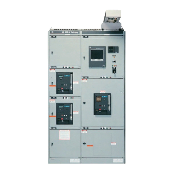
- Page 1 GE Consumer & Industrial Electrical Distribution AKD-10 Application Guide Featuring WavePro ™ Low Voltage Power Circuit Breakers imagination at work...
-
Page 2: Table Of Contents
Contents General description ............3 Safety and reliability features . -
Page 4: General Description
Switchgear short circuit ratings are based on two 30-cycle withstand tests with 15-second interval, AKD-10 switchgear sections are provided in either 22", 30" or performed at 15% power factor and 635 Vac maximum. For 38" widths. It is designed to be operated in an ambient tem- switchboards, a single 3-cycle withstand test at 20% power perature between -30°C and 40°C (-22°F and 104°F). -
Page 5: Safety And Reliability Features
Safety and reliability features Standard and optional features are available with AKD-10 switchgear in order to meet the increasing industry emphasis on maximum uptime, system reliability and operating personnel safety: • Closed-door operation Breaker compartment doors have no ventilation openings, thus protecting oper- ators from hot ionized gases vented by the breaker during circuit interruption. - Page 6 A superior bus system offers different levels of protection: • Fully tin-plated copper bus Fully tin-plated copper main and riser bus is a standard feature on AKD-10 equipment. Tin plating provides superior corrosion protection, especially for application in the pulp and paper and waste treatment industries where corrosive agents routinely exist.
- Page 7 • Drawout padlock provision (standard) WavePro and AKD-10 offer an array of standard, safety locking features that provide extra measures of security when breaker, equipment, or load mainte- nance is performed. In addition to the padlocking feature on the breaker that keeps it open and tripfree, WavePro breakers are also equipped with provisions ...
- Page 8 • Key interlocks This option allows locking of the circuit breaker in the open, trip-free position when fully connected. Applicable schemes would be mechanical interlocking of two breakers so only one can be closed at a time, or, in load center unit substa- tions, interlocking of the primary switch and secondary main breaker such that the secondary main must be open before the primary switch can be operated.
- Page 9 GE’s manufacturing processes and testing set the quality standards in the switchgear industry: • Paint finish AKD-10 switchgear is protected by the “E-coat” paint system consisting of a “cathodic electrodeposition” process employing the same principle used in electroplating: An electrically charged object immersed in a bath of oppositely charged particles will attract, and become coated with, those particles.
- Page 10 = 0 indicates the switchgear is installed at ground level. z/h > 0 indicates the switchgear may be installed anywhere in the building. AKD-10 has been certified for use in all IBC-2003 Seismic Use Groups, Occupancy Importance Factors and Seismic Design Categories. In addition, AKD-10 has been qualified to IEEE-693-1997 for Moderate and High Seismic loading conditions.
-
Page 11: Power Leader Power Management System
EPM 9000 series. These devices boast a broad range of power quality problems. With just a few clicks of a mouse, capabilities for a variety of uses including: usage monitoring, you can gain real-time access to the family of GE Multilin cost allocation, load monitoring, demand tracking, common ™... -
Page 12: Power+ ™ , Microversatrip Plus ™ And Pm ™ Trip Units
The Power+ trip unit is a new addition to the list of trip units • Rating plug with test port available on GE low voltage power circuit breakers. It continues Protection to use GE’s proven technique of measuring true rms currents •... -
Page 13: Application Data
Application data Table 12.1 WavePro Breaker Interrupting Ratings Short-Circuit Ratings Rated AC RMS Symmetrical kA Basic ratings Voltage, With Without ™ WavePro low voltage power circuit breakers are available in Nominal Breaker Frame Short-Time Instantaneous Instantaneous (max) Type Size (amps) Withstand Trip Trip various levels of interrupting capacity (IC) and are identified WPS-08... -
Page 14: Accessories & Electrical Characteristics
Accessories feature that will prevent the breaker from being manually closed until the lockout is reset. Reset of the contacts and Auxiliary Switch – lockout feature is accomplished by pushing the yellow “reset” Field installable kit available button on the breakerescutcheon. The reset button also serves (Breaker accessory) as a target indicator that the bell alarm has been operated. - Page 15 (WPS-20, 32, 40 or 50) must be ordered with the open fuse require the key to be removable when the breaker is able to lockout — character 3 in the breaker catalog number — when be closed or when the lock bolt is withdrawn. Up to two key it is to be used in a high short circuit application requiring positions can be accommodated in each breaker cubicle.
- Page 16 Remote Charge Indicator Switch – Field installable kit available (Breaker accessory) The remote charge indicator switch is a normally open or normally closed dry contact that changes state when the closing springs of the breaker are fully charged. This option is Operations Counter –...
- Page 17 Table 16.1 WP-08 / 16 / 20 circuit breakers the use of a shunt trip). The shunt trip coil is rated for inter- mittent duty and is supplied with an auxiliary switch contact Nominal Spring charging Charge / Charging Closing coil Voltage motor (amps) control...
-
Page 18: Repetitive Duty
85% of rated voltage and will drop out the minimum performance, as indicated in Table 18.1. With instantaneously between 30 and 60% (nonadjustable) of rated adequate maintenance, GE breakers can be expected to voltage. An electronic module on the undervoltage device ™... -
Page 19: Design Considerations
This standard applies to all parts of a circuit breaker that Temperature derating factors function during normal operation. It does not apply to other The continuous current rating of WavePro breakers is based parts, such as overcurrent tripping devices that function on their use in an enclosure at 40°... -
Page 20: Time Current Tripping Characteristics
Cable terminations Cables used for low voltage power circuit breaker terminations in AKD-10 must have minimum 90°C insulation while the cables’ ampacity will be based on a 75°C rating. This meets the requirements of ANSI C37.20.1, UL1558 and the National Electrical Code. - Page 21 9 10 60 70 80 90 .7 .8 .9 1 8 9 10 MULTIPLES OF CURRENT SETTING (C) MULTIPLES OF INSTANTANEOUS PICKUP SETTING GE Consumer & Industrial - DES-001B Low-Voltage Power Circuit Breakers Electrical Distribution Type WavePro with Available Ratings (Amperes) MicroVersaTrip Plus &...
- Page 22 1000 1000 .5 .6 .7 .8 .9 1 6 7 8 9 10 50 60 70 8090 MULTIPLES OF GROUND FAULT PICKUP SETTING GE Consumer & Industrial - DES-002B Low-Voltage Power Circuit Breakers Electrical Distribution Type WavePro with Available Ratings (Amperes) MicroVersaTrip Plus &...
-
Page 24: The Load Center Principle
For these types of systems, the use of higher-rated or WPF GE offers a complete line of load center unit substations for fused circuit breakers may be required to stay within the indoor or outdoor installations. The unit consists of an short-circuit rating of the feeder breaker. - Page 25 at high short-circuit currents. This combination of trip char- transformer rating at 208Y/120 volts and 100% of acteristics permits application of short-time delay trips to transformer rating at 240, 480, and 600 volts override inrush currents to downstream loads and coordinate •...
-
Page 26: Power Circuit Breaker Selection Tables
Power circuit breaker selection tables Table 25.1 Transformer forced cooled ratings Main Feeder circuit breakers Fully rated or Zone Self-cooled selective Selective selective Fully rated Transformer type % increase with fans Fully rated arrangement Liquid filled: 65° C rise 750-2000 2500-5000 Liquid filled: 55/65°... - Page 27 Table 26.1 Transformer forced cooled ratings Main Feeder circuit breakers Fully rated or Zone Self-cooled selective Selective selective Fully rated Fully rated Transformer type % increase with fans arrangement Liquid filled: 65° C rise 750-2000 2500-5000 Liquid filled: 55/65° C rise 750-2000 15% (fans) + 12% (65°...
- Page 28 Table 27.1 Transformer forced cooled ratings Main Feeder circuit breakers Fully rated or Zone Self-cooled selective Selective selective Fully rated Fully rated Transformer type % increase with fans arrangement Liquid filled: 65° C rise 750-2000 2500-5000 Liquid filled: 55/65° C rise 750-2000 15% (fans) + 12% (65°...
- Page 29 Table 28.1 Transformer forced cooled ratings Main Feeder circuit breakers Fully rated or Zone Self-cooled selective Selective selective Fully rated Fully rated Transformer type % increase with fans arrangement Liquid filled: 65° C rise 750-2000 2500-5000 Liquid filled: 55/65° C rise 750-2000 15% (fans) + 12% (65°...
-
Page 30: Ground Detection Considerations
Ground detection considerations High resistance pulsing ground detection system This system provides a means for grounding the neutral of an ungrounded power system, utilizing the “high-resistance” method. It allows the switchgear to operate as an “ungrounded” system but eliminates the danger of high transient overvoltage during certain types of ground faults. - Page 31 Table 30.1 Operation with alarm relay Ground fault protection on solidly grounded systems The preferred method of providing ground fault protection Option Operational description ™ on WavePro power circuit breakers is using the ground An overvoltage relay coil Operation with the alarm relay is the same as rating of 199 to 208V, pickup described in Table 29.1, although the connections ™...
-
Page 32: Automatic Transfer (Throwover) Equipment
Automatic transfer (throwover) equipment breakers is opened. The position switch contacts allow normal operation of the breakers during maintenance situations Relay and control equipment can be provided to maximize where one or more of the interlocked breakers may be continuity of service to a switchgear load bus by transferring racked out to the TEST or DISCONNECT position or withdrawn the load bus to an alternate or emergency power source in from the compartment. -
Page 33: Sizing And Dimensional Data
Typical AC switchgear sections, 635V maximum, switchgear line-up. Refer to Tables 31.1 and 31.2 for properly sizing AKD-10 line-ups. The depth of the entire line-up is 50/60 Hz determined by the deepest device in the line-up. For example,... -
Page 34: Switchgear Layout And Sizing
1. Sections can be bussed together if there are matching bus levels 11. Some cable entrance designs are not suitable for service in the adjacent sections. Refer to the sample AKD-10 line-up below. entrance. Consult the factory if service entrance is required for 2. - Page 35 22” Main/tie sections LEGEND & NOTES MID BUS LEVEL IS NOT AVAILABLE AT 5000A BUSWAY CONNECTION (USE ONLY UPPER OR LOWER BUS LEVELS) OUTGOING INCOMING FEEDER CABLE CONNECTION CABLE CONNECTION (OTHER THAN FEEDER BREAKER) 92" 800- 1600A UPPER 21" 21" 21"...
- Page 36 22” Main/tie and feeder sections LEGEND & NOTES MID BUS LEVEL IS NOT AVAILABLE AT 5000A BUSWAY CONNECTION (USE ONLY UPPER OR LOWER BUS LEVELS) OUTGOING INCOMING FEEDER CABLE CONNECTION CABLE CONNECTION (OTHER THAN FEEDER BREAKER) 92" 800- 800- 800- 800- 1600A 1600A...
- Page 37 22” Feeder sections, 22/30" auxiliary sections LEGEND & NOTES MID BUS LEVEL IS NOT AVAILABLE AT 5000A BUSWAY CONNECTION (USE ONLY UPPER OR LOWER BUS LEVELS) OUTGOING INCOMING FEEDER CABLE CONNECTION CABLE CONNECTION (OTHER THAN FEEDER BREAKER) 92" BUSWAYS BUSWAYS 800- 800- ABOVE=FRONT POS'N...
- Page 38 30” Main/tie sections LEGEND & NOTES MID BUS LEVEL IS NOT AVAILABLE AT 5000A BUSWAY CONNECTION (USE ONLY UPPER OR LOWER BUS LEVELS) OUTGOING INCOMING FEEDER CABLE CONNECTION CABLE CONNECTION (OTHER THAN FEEDER BREAKER) 92" UPPER 14" 14" 14" 28" 3200- 3200- 3200-...
- Page 39 30” Main/tie sections LEGEND & NOTES MID BUS LEVEL IS NOT AVAILABLE AT 5000A BUSWAY CONNECTION (USE ONLY UPPER OR LOWER BUS LEVELS) OUTGOING INCOMING FEEDER CABLE CONNECTION CABLE CONNECTION (OTHER THAN FEEDER BREAKER) 92" 14" 14" 28" 28" 3200- 3200- MAIN MAIN...
- Page 40 30/38” Main/tie sections LEGEND & NOTES MID BUS LEVEL IS NOT AVAILABLE AT 5000A BUSWAY CONNECTION (USE ONLY UPPER OR LOWER BUS LEVELS) OUTGOING INCOMING FEEDER CABLE CONNECTION CABLE CONNECTION (OTHER THAN FEEDER BREAKER)
- Page 41 30/38” Main/tie sections LEGEND & NOTES MID BUS LEVEL IS NOT AVAILABLE AT 5000A BUSWAY CONNECTION (USE ONLY UPPER OR LOWER BUS LEVELS) OUTGOING INCOMING FEEDER CABLE CONNECTION FEEDER CUBICLES ARE NOT AVAILABLE WHEN 3200A AND 4000A BREAKERS HAVE 100KA CABLE CONNECTION (OTHER THAN FEEDER BREAKER) SHORT CIRCUIT RATING 92"...
- Page 42 30" Feeder sections LEGEND & NOTES MID BUS LEVEL IS NOT AVAILABLE AT 5000A BUSWAY CONNECTION (USE ONLY UPPER OR LOWER BUS LEVELS) OUTGOING INCOMING FEEDER CABLE CONNECTION FEEDER CUBICLES ARE NOT AVAILABLE WHEN 3200A AND 4000A BREAKERS HAVE 100KA CABLE CONNECTION (OTHER THAN FEEDER BREAKER) SHORT CIRCUIT RATING 92"...
- Page 43 30" Main/tie/feeder sections, 38" auxiliary sections LEGEND & NOTES MID BUS LEVEL IS NOT AVAILABLE AT 5000A BUSWAY CONNECTION (USE ONLY UPPER OR LOWER BUS LEVELS) OUTGOING INCOMING FEEDER CABLE CONNECTION CABLE CONNECTION (OTHER THAN FEEDER BREAKER)
-
Page 44: Power Leader ™ Instrument Door
POWER LEADER™ instrument door (minimum compartment size) Pulsing High Resistance Ground System EPM9xxx & Nexus Touch Screen 14" 5.4" 21" 8.0" 22" 22" EPM6000 Meter & EPM 9xxx 3-Line Display PQM II 7.35" 4.38" 14" 4.35" 14" 4.38" 22" 22" Power Leader Modbus Monitor 11.5"... -
Page 45: Breaker Instrument Panel
Instrument Panels Instrument panels that house various control devices for ™ WavePro breakers are furnished above each breaker cubicle. Deadfront fuse holders are provided for charge, close and trip circuits. When requested, green and red indicating lights can be provided to show the breaker open/close status. A third indicating light position can be used to show spring charge status or trip-on-fault. -
Page 46: Floor Plans And Side Views
AKD-10 NEMA 1 indoor — side view and anchoring details Note: Refer to installation drawing and AKD-10 switchgear installation manual (DEH-194) for additional information If line-up includes any WPF-08/16 breakers Refer to Table 32.1 and 32.2 for equipment depth options. - Page 47 NEMA 1 indoor — floor plan and cable space details Note: Refer to installation drawing and AKD-10 switchgear installation manual (DEH-194) for additional information Direction Rear Equipment Extension Transformer Flange CL Depth Cables Depth to Rear of Switchgear 60” Non-fused 19.00...
- Page 48 NEMA 3R outdoor, non-walk-in — side view and anchoring details Note: Refer to installation drawing and AKD-10 switchgear installation manual (DEH-194) for additional information *Busway to main bus only, 5000A breaker not available in outdoor non-walk-in construction. Refer to Table 32.1 and 32.2 for equipment depth options.
- Page 49 NEMA 3R outdoor, non-walk-in — floor plan and cable space details Note: Refer to installation drawing and AKD-10 switchgear installation manual (DEH-194) for additional information Non-fused breakers (14" rear extension) With WPF-08/16 (7" rear extension) z With 5000 Amp Main Bus and WPF-08/WPF-16 { 5000 Amp Bus w/o WPS/WPX-50 and w/o WPF-08/16 (7"...
- Page 50 NEMA 3R outdoor, walk-in protected aisle — side view and anchoring details Note: Refer to installation drawing and AKD-10 switchgear installation manual (DEH-194) for additional information Refer to Table 32.1 and 32.2 for equipment depth options.
- Page 51 NEMA 3R outdoor, walk-in protected aisle — floor plan and cable space details Note: Refer to installation drawing and AKD-10 switchgear installation manual (DEH-194) for additional information Non-fused breakers (14" rear extension) With WPF-08/16 (7" rear extension) z With 5000 Amp Main Bus and WPS/WPX-50 { 5000 Amp Bus w/o WPS/WPX-50 and w/o WPF-08/16 (7"...
-
Page 52: Wavepro Breaker Wiring Diagram
Breaker Wiring Diagram (6) TWO SHUNT TRIP DEVICES REQUIRE A 7-STAGE AUXILIARY SWITCH. (7) A SECOND SHUNT DEVICE IS NOT AVAILABLE FOR WPS-50 Notes: TYPE BREAKERS. (1) BREAKER SHOWN IN THE OPEN POSITION WITH THE (8) THE FOLLOWING DEVICES ARE NOT APPLICABLE ON CLOSING SPRINGS DISCHARGED, BELL ALARM RESET. - Page 53 UV/ELO OFLO OFLO OFLO PH.A PH.B PH.C OPEN FUSE LOCKOUT BELL ALARM CONTACTS UNDERVOLTAGE OR (WPS-20, WPS-32, WPS-40, (SHOWN WITH OR WITHOUT ELECTRIC LOCKOUT & WPS-50 FRAMES ONLY) LOCKOUT OPTION) (TAP) (COM) TRIP UNIT REMOTE CHARGE INDICATOR – NEUTRAL SENSOR REMOTE CHARGE INDICATOR –...
-
Page 54: Wavepro Breaker Catalog Number Guide
Code none (non-automatic) AKD10/PBII/AV3 Access Equipment WE MVT Plus Special “dead front shield” for use in W1 MVT M (metering & communications) B AKD-10/PBII/AV3 Access Equipment MVT PM (relaying, metering & communications) Interrupting Capability/ Silver MVT Plus (w/special GF curve) - Page 55 Breaker Operation & Control Voltages Breaker Mounted Accessories Operation AccessoryCode Future use Charge & Close Code none manual Aux switch manual with remote close x 4 stages Aux switch Close voltage 7 stages 120v-60Hz 240v-60Hz Accessory Accessory Code 120v-50Hz Bell Alarm Push Button Cover 240v-50Hz 48v -DC...
-
Page 56: Guideform Specifications
• Power factor meter • Watthour meter [2/2 ⁄2 /3] elementsThe type AKD-10 Low Voltage Switchgear shall be rated { } • Current/voltage test block and plug PK-2 Volts, 3-phase, [3-wire/4-wire with 50% neutral/4-wire with • Potential transformers with primary fuses 100% neutral], [50/60] Hz. -
Page 57
. The cable compartment by glass reinforced polyester barriers. section(s) shall have hinged doors over each compartment. No live connections shall be accessible from the rear except the breaker load side termination.>... - Page 58 Grounding of the breaker frame to the switchgear shall be to suppress arcs and cool vented gases. Interphase barriers maintained throughout the travel of the drawout mechanism. of insulating material shall be provided to isolate each pole Padlocking provisions shall permit locking of the breaker in of the breaker.
- Page 59 The housing shall be a metallic enclosure to protect Detailed specifications against magnetic interference, dust and other ™ This specification covers GE WavePro low voltage power contaminants. circuit breakers, types WPS, WPH, WPX, WPF. b. The protective system shall have reliable programmable controls with repetitive accuracy and precise unit settings.
- Page 60 3. The trip units for the main and tie breakers shall include b. The protective system shall have reliable programmable the following protective functions: controls with repetitive accuracy and precise unit settings. a. Adjustable long time current settings. c. All current sensing shall employ true rms technology for b.
-
Page 61
1)
adjustable delay - 1 to 15 seconds. 2) - Page 62 Protection and control 1 applications or an IR crystal window for outdoor NEMA 3R applications. IR windows shall have a gasketed cover plate Automatic throwover equipment shall be provided to transfer secured with tamper-resistant hardware.> a load bus to an alternate source [immediately/ with a time delay] after detection of an abnormal condition on the normal
Page 63: Standards And References
Trip Unit Users Manual National Electrical Manufacturers Association (NEMA) General installation and maintenance DEH-194 – AKD-10 Low-Voltage Switchgear Installation (NEMA has “approved and adopted” the parallel ANSI Manual switchgear and breaker standards in lieu of continued support DEH-136 – WP08/16/20 Maintenance Manuals of the SG3 and SG5 standards.)- Page 64 Notes...
- Page 65 Notes...
- Page 66 GE Consumer & Industrial 41 Woodford Avenue Plainville, CT 06062 www.geelectrical.com imagination at work DET-196B (05/07)
- Page 62 Protection and control 1 applications or an IR crystal window for outdoor NEMA 3R applications. IR windows shall have a gasketed cover plate Automatic throwover equipment shall be provided to transfer secured with tamper-resistant hardware.> a load bus to an alternate source [immediately/ with a time delay] after detection of an abnormal condition on the normal