
Related Manuals for Panasonic KW4M


Summary of Contents for Panasonic KW4M
- Page 2 Copyright and trademark ● Panasonic Electric Works Co., Ltd. owns the copyright of this manual. ● We stiffly refuse the reproduction of without permission from this manual. ●Modbus Protocol is a communication protocol that the Modicon Inc.developed for PLC.
- Page 3 Introduction Thank you for indeed for purchasing “KW4M Eco-POWER METER” for this time. In this manual, we explain the usage of “KW4M Eco-POWER METER” in detail. Please use it correctly after understanding the content enough.
-
Page 4: Table Of Contents
Table of Contents Cautions before using ..........................ⅰ Chapter 1 Unit’s Features and Structure....................1 1-1 Features..............................1 1-2 Unit’s Name and Part Numbers....................... 1 1-2-1 Main unit............................1 1-2-2 Dedicated Current Transformer (CT)..................... 1 1-2-3 Options............................1 1-3 Measurement items ..........................2 Chapter 2 Parts Name and Working ....................3 2-1 Parts Names ............................ - Page 5 Chapter 8 Specifications ........................33 8-1 Main unit ..............................33 8-2 Input Specifications ..........................34 8-2-1 Power Input..........................34 8-2-2 Pulse input specifications......................35 8-3 Pulse output (Transistor output) Specifications..................35 8-4 Communication Specifications ......................36 8-5 Dedicated Current Transformer Specifications ..................36 8-6 Self-diagnostic function .........................
-
Page 6: Cautions Before Using
Cautions before using ■ Installation environment ◇Do not use the Unit in the following environments. ・Where the unit will be exposed to direct sunlight and where the ambient temperature is outside the range of -10 to 50 °C. ・Where the ambient humidity is outside the range of 30 to 85 % RH (at 20℃ non-condensing) and where condensation might occur by sudden temperature changes ・Where inflammable or corrosive gas might be produced ・Where the unit will be exposed to excessive airborne dust or metal particles... -
Page 7: Features
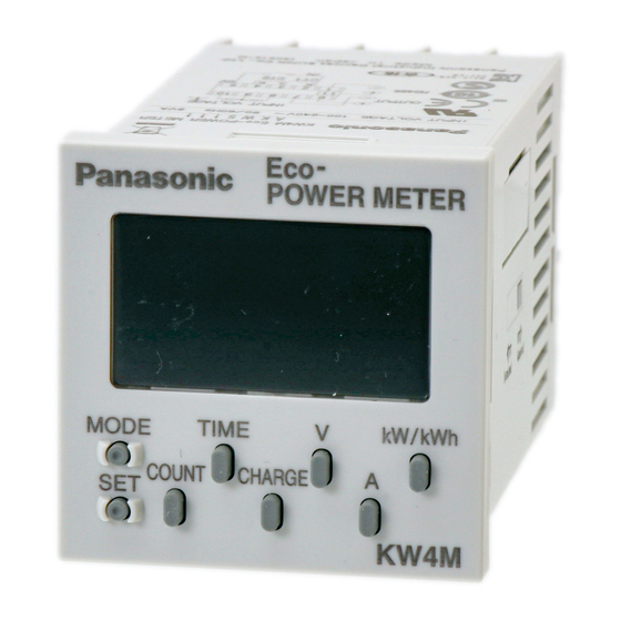
Unit’s Features and Structure 1-1 Features ■KW4M Eco-POWER METER is a wattmeter in DIN48 size. Electrical energy (voltage, current, etc.) is measured using AC voltage and AC current input via one of the following systems: single-phase two-wire system, single-phase three-wire system, or three-phase three-wire system. -
Page 8: Measurement Items
1-3 Measurement items Item Unit Data displayed range Instantaneous electric power 0.00 to 9999.99 0.00 to 9999.99kWh to 10.00MWh to Integrated electrical energy 9999.99MWh 9-digit display: 0.00 to 9999999.99 kWh L1(CT1)-phase current 0.0 to 6000.0 Current L2(CT2)-phase current 0.0 to 6000.0 Voltage between 1-2 0.0 to 9999.9 Voltage... -
Page 9: Chapter 2 Parts Name And Working
Chapter 2 Parts Name and Working 2-1 Parts Names ① Mode name display (16-segment) ② ① ② Lock indicator Light is on when locked. ③ ③ Mode indicator Light is on when the mode is being set. ⑥ ④ ④ Output indicator Light is on when pulse is output. -
Page 10: Chapter 3 Display Of Each Value
Chapter 3 Display of each Value 3-1 Instantaneous electric power / Integrated Electrical energy ・Presskey to display the instantaneous electric power and integrated electrical energy. ・Press key to change the instantaneous electric power to integrated electrical energy. *Displayed data is updated at every 1 second. Instantaneous electric power(kW) →... -
Page 11: Current
3-2 Current ・Press key to display the current value of the load. ・Press key to change L1(CT1)-phase current to L2(CT2)-phase current *Displayed data is updated at every 1 second. → L1(CT1)-phase current (A) L2(CT2)-phase current (A) Sample of L1(CT1)-phase 30.0A Sample of L2(CT2)-phase 30.1A ... -
Page 12: Electricity Charge
3-4 Electricity Charge It displays the standard electricity charge or corresponding value for the integrated electrical energy. ・Presskey to display the electricity charge and corresponding value. ・At electricity charge display, press key to change between JPY, $, EUR, CNY, CHG and CO2. →... -
Page 13: Count Value / Preset Value
*After reaching the full scale (99999.9h), the value reverts to 0.0h but continues to measure. CT Detection Full scale ON-time OFF-time How to Reset ON/OFF-time ・Presskey while pressing key makes ON / OFF-time clear. Reset 3-6 Count Value / Preset Value It displays present count value (pulse input value) and preset value. -
Page 14: Chapter 4 Various Functions
Chapter 4 Various Functions 4-1 LOCK mode It is the mode makeskey and Select keys unable. Use when you want to fix one of the measurement displays (For all displays). When you press key continuously for about 3sec., the “LOCK” indicator lights and key and Select keys become locked (pressing them will have no effect). -
Page 15: Chapter 5 Settings
Chapter 5 Settings 5-1 Operation procedure Each setting is classified as follows. There are the detailed explanations from next pages. ・MODE:…Mode for selection of Power measurement (Power meter) or Pulse measurement (Pulse counter). ・MODE1: + … Mode for setting each parameter for power measurement. ・MODE2: +... -
Page 16: Setting Mode Explanation
5-2 Setting Mode Explanation ■The value with under line is initial setting among each setting value. ☆Set before measurement. 5-2-1 MODE (Select input method) <MODE> Input method setting mode Mode defines input method, power measurement or pulse measurement. ・Select from POWER / COUNT ・“POWER”... - Page 17 C U T A Cutoff current setting mode Mode defines load current that does not measured (Cutoff current). Use to avoid miss-measurement by wiring or induction noise at no-load. 0.00kW is displayed for instantaneous electric power, 0.0A is displayed for current. Integrated electrical energy is not measured.
-
Page 18
VT ratio setting mode Factory setting / Display ・Enter VT ratio using
,< A >,< V >, . ・ If the VT is 440/110, set to “ 4.00 ”. (1.00~99.99) ↓ Current for time measurement setting mode Factory setting / Display ・... -
Page 19: Mode2
5-2-3 MODE2 (Mode for setting each parameter for pulse measurement. This mode doesn’t show when power measurement is selected.) <MODE>+< A > Max. counting speed setting mode Mode defines max. counting speed. ・Select from 2kHz/30Hz P S C L Pre-scale setting mode Mode defines pre-scale value used for change count value. -
Page 20: Mode3
5-2-4 MODE3 (Mode for setting of each parameter for serial communication (RS-485)) <MODE>+< V > N O . Station number setting mode Mode defines an individual station no. for each unit when two or more units communicate via serial communication (RS-485). ・It can be set the range of 01 to 99. -
Page 21: Mode4
Response time setting mode Factory setting / Display Enter the response time using, < A >. ・ Response time can be entered the range of 05 to 99ms. ↓ Normal display 5-2-5 MODE4 (Mode for setting of each parameter for optional function) <MODE>+<CHARGE>... -
Page 22: Chapter 6 Installation And Wiring
Chapter 6 Installation and Wiring 6-1 Panel Cut-out dimensions (Unit: mm) +0.6 Dimension A when ‘u’ products are mounted in a row: A=(48*n-2.5) If the products are mounted in a row, they lose their waterproofing properties. 6-2 Panel mounting diagram How to mount From the panel front, pass the main unit through the square holes. -
Page 23: Wiring
6-3 Wiring 6-3-1 Terminal arrangement Terminal No. Functions Pin type Screw terminal type ① ⑧ 1, R, R ② ⑨ 2, N, S ③ ⑩ 3, T, T ⑪ ④ (+) RS-485 ⑤ ① (-) ⑥ ⑥ (+) Pulse output ⑦... - Page 24 ②Single-phase 3 wire system / Three-phase 3 wire system *Two CTs are required to measure Single-phase 3-wire / Three-phase 3 wire system. < Pin type > <Screw terminal type> 2) When measuring load with 200V or more system VT (Voltage transformer) is needed when you measure a load with voltage over 200V system. Use commercial VT, those secondary rating is 110V.
- Page 25 ◇To connect CT with secondary current 5A How to connect the unit to measure by combination with existing commercial CT (1) Select 5A at CT type setting mode (CT-T). (2) Set the primary current of measured commercial CT (secondary current 5A) at primary side current of CT setting mode (CT-1).
-
Page 26: Pulse Measurement
6-3-3 Pulse measurement ◇Main unit wiring diagrams < Pin type > <Screw terminal type> ◇Input connection ・Contact input Use highly reliable metal plated contacts. Since the contact’s bounce time leads directly to error in the count value, use contacts with as short a bounce time as possible. In general, ⑤... -
Page 27: For Output Connection
6-3-4 For Output connection Since the transistor output is insulated from the internal circuit by a photo-coupler, it can be used both as a NPN output and PNP (equal value) output. Eco-POWER METER Eco-POWER METER NPN output Pulse(+) Pulse(-) PNP output Pulse(+)... -
Page 28: Low Voltage Directive
Recommended Cable Use the transmission cables shown below for Eco-POWER METER RS485 communication system. Conductor Insulator Cable Cable Resistance Applicable cable diameter Size Material Thickness (at 20℃) HITACHI 1.25 mm KPEV-S Max. Approx. (AWG16) Max.16.8Ω/km Polyetheline ×1P 0.5 mm 8.5 mm 1.25 mm or more Twisted-... -
Page 29: Chapter 7 Communications
Chapter 7 Communications 7-1 Communication Procedures Communication starts with command transmission from the host computer (hereafter Master) and ends with the response of Eco-POWER METER (hereafter Slave). Master Slave • Response with data Command When master sends reading command, slave responds with the Data corresponding set value or current status. -
Page 30: Mewtocol Communication
7-3 MEWTOCOL communication 7-3-1 Overview of MEWTOCOL-COM (RS-485) ◆Command and response functions The computer sends commands (instructions) to Eco-POWER METER, and receives responses in return. This enables the computer and Eco-POWER METER to converse with each other, so that various kinds of information can be obtained and provided. ①Commands Computer Eco-POWER METER... -
Page 31: Data Register List
7-3-2 Data Register List Data register Name Unit Kind of data Range Rate ¥(JPY) DT00050 0.1¥ 0 to 99.9 Sign-less 16bit Rate $ 0.001$ DT00051 0.000 to 9.999 Sign-less 16bit DT00052 Rate €(EUR) 0.001€ 0.000 to 9.999 Sign-less 16bit DT00053 Rate yuan (CNY) 0.01 yuan 0.00 to 99.99... -
Page 32: Error Codes
4) If each setting value is wrote by communication, it memories to internal EEP-ROM at the same time. Therefore, change setting frequently makes EEP-ROM’s life short. Avoid to usage like this. 5) Write a data within the range when you write it. 7-3-3 Error Codes ◇Basic procedure errors Error code... - Page 33 ◆[RD]: Read data area (Reads the contents of data area.) ◇Command Ending word No. Starting word No. Destination % # 5 characters 5 characters ×10 ×10 ×10 ×10 ×10 ×10 ×10 ×10 ×10 ×10 ×10 ×10 ×16 ×16 ◇Normal response (Read successful) First register contents Last register contents Source...
-
Page 34: Modbus (Rtu) Communication
7-5 MODBUS (RTU) Communication 7-5-1 Overview of MODBUS (RTU) ◆8-bit binary data in command is transmitted as it is. Data format Start bit : 1 bit : 8 bits ※7bits is not available. Data bit Parity : No parity, Even parity, Odd parity Selectable Stop bit : 1 bit (Fixed) Error detection... - Page 35 ◇Data: Data depends on the function code. A request message from the master side is composed of data item, number of data and setting data. A response message from the slave side is composed of number of bytes, data and exception code in negative acknowledgement.
- Page 36 ③ Reset integrated electric power (0064H, 0065H:2-word) of address 1 (When setting to 0 [0000, 0000H]) ・Command Number of Slave Function Data item Number of 3.5 idle data item to ⇒ address code data characters write (01H) (10H) (0064H) (04H) (0002H) ←character number...
-
Page 37: Data Register List
7-4-2 Data Register List MODBUS Range: Hexadecimal Data item Function Name Unit Kind of date (Range: Decimal) (MEWTOCOL) code 0H~270FH 0032H Sign-less Rate ¥(JPY) 03H/06H/10H 0.01 (DT00050) 16bit (0~9999) Sign-less 0033H 0H~270FH 03H/06H/10H Rate $ 0.001$ (DT00051) 16bit (0~9999) 0034H Sign-less 0H~270FH 03H/06H/10H... - Page 38 009AH (DT00154) Sign-less 0H~F423FH - 03H/06H/10H Pulse count value 32bit (0~999999) 009BH (DT00155) 009EH 0H~F423FH (DT00158) Sign-less - 03H/06H/10H Preset value 32bit (0~999999) 009FH (DT00159) 00A0H 1H~186A0H (DT00160) Sign-less 0.001 03H/06H/10H Pre-scale value (1~100000) 32bit 00A1H *Decimal point is fixed. (DT00161) 00A2H Sign-less...
-
Page 39: Chapter 8 Specifications
Chapter 8 Specifications 8-1 Main unit Rated operating voltage 100-120/200-240V AC Rated frequency 50/60Hz common Rated power consumption Allowable operating 85-132/170-264V AC(85%~110% of rated operating voltage) voltage range Allowable momentary 10ms power-off time Ambient temperature -10~+50℃(-25℃ to +70℃ at storage) Ambient humidity 30~85%RH(at 20℃... -
Page 40: Input Specifications
8-2 Input Specifications 8-2-1 Power Input Instantaneous electric power (kW) Power Integrated electrical energy (kWh, MWh) Voltage Each phase Voltage (Between 1 and 2, 2 and 3) (V) Measuring Each phase Current item Current (L1(CT1)-phase current, L2(CT2)-phase current) (A) Electricity charge Integrated electricity charge (JPY,$,EUR,CNY) Power-on time Hour Meter (Load ON-time, Load OFF-time) (hour) -
Page 41: Pulse Input Specifications
Instantaneous electric power, Integrated electrical energy Voltage, Current, Electricity charge, Corresponding value ±2.5% F.S. ±1digit (at 20℃, rated input, rated frequency, power-factor 1) Basic ※Accuracy coverage:10~100% of rated current of CT accuracy Accuracy Hour Meter (without error ±0.01%±1digit (at 20℃) in CT and VT) (In case power on start or current energizing,±0.01%+1s±1 digit) ±1.5% F.S. -
Page 42: Communication Specifications
8-4 Communication Specifications Interface Conforming to RS-485 Protocol MEWTOCOL/MODBUS (RTU) (different model) Isolation status Isolated with the internal circuit ※ ※ Number of connected units 99 (max.) Transmission distance 1200m Transmission speed 38400/19200/9600/4800/2400bps (selectable with setting mode) 8bit/7bit (selectable with setting mode) (MEWTOCOL type) Data length 7bit (fixed) -
Page 43: Self-Diagnostic Function
8-6 Self-diagnostic function If an error occurs, the following indication will be given. Indicator Meaning Output status To recover Err-00 CPU error Turn the power off and then on again. Err-01 Memory error* EEP-ROM life ended. Replace the unit. *Includes the possibility that the EEP-ROM’s life has expired. Chapter 9 Dimensions 9-1 Main unit (Unit: mm) -
Page 44: Dedicated Ct
9-2 Dedicated CT (Unit: mm) (Clearance: ±1.0) ◆For 5A/50A(AKW4801) ◆For 100A(AKW4802) ◆Attached trunk cable: L=(1000) - Page 45 ◆For 250A(AKW4803) ◆For 400A(AKW4804)...
- Page 46 Revision History Issue Date Manual no. Content of revision June, 2005 ARCT1F413E First edition October, 2007 ARCT1F413E-1 Second edition 6-3 Wiring: Add the explanation in detail. March, 2008 ARCT1F413E-2 Third edition MODBUS type series addition ・Model No. ・MODBUS communication ・MODBUS specifications October, 2008 ARCT1F413E-3 Fourth edition...