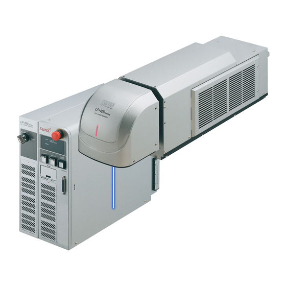
Panasonic LP-400 Series External Control Manual
Laser marker
Hide thumbs
Also See for LP-400 Series:
- Operation and maintenance manual (334 pages) ,
- Operation manual (10 pages)

Related Manuals for Panasonic LP-400 Series


Summary of Contents for Panasonic LP-400 Series
- Page 1 Laser Marker External Control Manual LP-400 series LP-V series LP-W series ME-LP400V-EX-6 No. 9000-0062-17V 2018.7 panasonic.net/id/pidsx/global...
-
Page 2: Preface
Preface Thank you for purchasing our product. For full use of this product safely and properly, please read this document carefully. This product has been strictly checked and tested prior to its delivery. However, please make sure that this product operates properly before using it. -
Page 3: Cautions In Handling
Cautions in Handling ALWAYS FOLLOW THESE IMPORTANT SAFETY PRECAUTIONS! To reduce the risk of injury, loss of life, electric shock, fire, malfunction, and damage to equipment or property, always observe the following safety precautions. The following symbols are used to classify and describe the level of hazard, injury, and property damage caused when the denotation is disregarded and improper use is performed. - Page 4 WARNING • Do not use this product anywhere where fire is strictly prohibited, near inflammable gas, objects or organic solvents such as thinner or gasoline, or in dusty place. There is a risk of fire. • Do not use this product in wet place. In addition, never conduct wiring or maintenance work with wet hands or when the product surface is wet.
- Page 5 WARNING • Remove the dust and/or gas which may be generated during the laser radiation with dust collector or exhauster. Use an appropriate dust collector or exhauster for dust or gas generated. Depending on the material of the objects, harmful dust and/or gas to the human body and the laser marker may be generated.
- Page 6 • Do not touch the laser emission port on the bottom of the head. They may affect the laser marking quality badly. • For LP-V / LP-W series, do not grasp the fiber unit when carrying the head part. • Carry the head as shown in the figure below. LP-400 series LP-V/LP-W series Fiber cable...
- Page 7 For the Proper Use of Product • Be sure to observe the following matters to prevent a failure or a malfunction of this product and to maintain the product performance properly. Wiring • Verify that the cables are wired correctly before powering on. •...
-
Page 8: How To Read This Document
Note that the illustration and the screen images may vary with model. Target model Description in the text LP-430U, LP-430TU LP-4xx(T)U LP-430 LP-4x0 LP-400 Series LP-430U-A, LP-430TU-A LP-4xx(T)U-A LP-430U-C, LP-430TU-C LP-4xx(T)U-C LP-430U-CHN, LP-430TU-CHN LP-4xx(T)U-CHN LP-420S9U, LP-420S9TU... - Page 9 ⿎ Symbol indications • “Notice” denotes any instructions or precautions for using this product. To prevent the Notice damage or malfunction of the product, observe these precautions fully. • “Reference” denotes any hints for operation, detail explanations, or references. Reference ⿎...
-
Page 10: Table Of Contents
Contents Preface ……………………………………………………………………………… 2 Cautions in Handling ………………………………………………………………… 3 How to Read this Document ……………………………………………………… 8 1 Before External Control …………………………………………… 12 1-1 Operation Method for Laser Marker …………………………………………13 1-1-1 Operation procedure of test marking and run mode …………………… 14 1-1-2 Test marking and run mode operation ……………………………………... - Page 11 3 Control by Serial Communication (RS-232/Ethernet) ………… 56 3-1 Preparation of Command Control ……………………………………………57 3-1-1 RS-232C ……………………………………………………………………… 57 3-1-2 Ethernet ……………………………………………………………………… 60 3-2 Command Reception Condition ………………………………………………62 3-3 Connection Check ………………………………………………………………63 3-4 Control Sample …………………………………………………………………64 3-5 Communication Data Format …………………………………………………68 3-5-1 Command data ………………………………………………………………...
-
Page 12: Before External Control
1 Before External Control ME-LP400V-EX-6... -
Page 13: Operation Method For Laser Marker
1-1 Operation Method for Laser Marker • It is obligated by IEC/FDA/JIS that laser products shall incorporate a key- actuated master control. Actuation of this product is basically controlled by the key switch located on the front of the controller. However, in considering CAUTION situations when the laser marker is operating as a part of a larger system, the laser marker turns on if the key switch is already in ON position, and power is... -
Page 14: Operation Procedure Of Test Marking And Run Mode
1-1-1 Operation procedure of test marking and run mode This section describes the basic operation procedures with the display operation connected to the controller. ⿎ Flow chart Turn on power with key switch on controller. For test marking For run mode operation File selection Edit the file Edit and overwrite the file... -
Page 15: Test Marking And Run Mode Operation
1-1-2 Test marking and run mode operation To irradiate the laser by the screen operation, operate the laser marker in test marking or run mode operation. ⿎ Test marking procedure Test marking executes the laser radiation manually with the selected file. Select “TEST”... -
Page 16: Operation By External Devices
1-2 Operation by External Devices 1-2-1 Operation method using external control device To control the laser marker with the external control device, the following connecting methods are applicable: External control using I/O : Remote mode operation Controls the laser marker from external devices such as PLC using various I/O signals loaded into the laser marker. For details, refer to “2 Control by I/O”... -
Page 17: Operation Procedure With External Control
1-2-2 Operation procedure with external control ⿎ Operation example when controlling the laser marker from external control devices such as Turn ON key switch of laser marker controller Remote mode ON Refer to “1-3-3 Shift to remote mode” (P.23). I/O control Control by serial communication commands Select file Laser pumping ON... -
Page 18: Before External Control
1-3 Before External Control The following settings are required before the external control by using I/O or communication commands. ⿎ Setting flow to start external control DIP switch setting • DIP switch No. 2: Select control method, I/O or command for some specific operations. •... -
Page 19: Dip Switch Setting
• For the details on DIP switch, refer to Operation/Maintenance manual. Turn OFF the power of laser marker. Remove the DIP switch cover on the rear of the controller. DIP switch LP-400 series LP-V/LP-W series Rear of controller With DIP switch No. 2, select the control method, I/O or command for some specific operations. - Page 20 With DIP switch No. 5, select the setting method of the remote mode. DIP switch No. 5 Setting method of remote mode Use the input signal of REMOTE IN (A3) on I/O terminal. OFF(initial setting) Use the remote switch on the front of the controller. Reference •...
-
Page 21: Communication Condition Setting
1-3-2 Communication condition setting To control the laser marker by using I/O or communication commands, configure the following items in advance on the environment setting screen. Select “ENVIRON” on the right menu. Select “ENVIRON 3”. To use I/O signals, configure the following output conditions: •... - Page 22 To use the serial communication commands, set communication conditions for Ethernet or RS- 232C. • For RS-232C: Configure the communication conditions of the laser marker corresponding to the external control device. • For Ethernet: Configure the communication conditions according to the network environment. •...
-
Page 23: Shift To Remote Mode
1-3-3 Shift to remote mode To control the laser marker externally using I/O or serial communication commands, set the operation mode to the remote mode in one of the following methods. Select the method to switch to the remote mode by setting the DIP switch on the rear side of the controller. Use the remote switch on the front of the controller. -
Page 24: Control By I/O
2 Control by I/O ME-LP400V-EX-6... -
Page 25: I/O Interface Specification
• Before using I/O, configure the DIP switch and the environment settings. Refer to “1-3 Before External Control” (P.18). • I/O terminal block is removable from the controller at the wiring. Rear of controller LP-400 series LP-V/LP-W series Laser marker side... -
Page 26: I/O Terminal Block
2-1-1 I/O terminal block I/O terminal block of the NPN type I/O terminal block of the PNP type [LP-4xx(T)U / LP-4xx(T)U-A / LP-4xxS9(T)U / [LP-4xx(T)U-C / LP-4xxS9(T)U-C / LP-VxxU-C] LP-4xxS9(T)U-A / LP-VxxU / LP-VxxU-A / LP-W series] Reference • A2, A11, B2 and B11 on the I/O terminal block have different signals depending on the controller type of NPN or PNP. •... -
Page 27: Signals And Details Of I/O Terminal Block
2-1-3 Signals and details of I/O terminal block The I/O terminal block is loaded with the basic input/output to control the laser marker. ⿎ Signals in I/O terminal No. *1 Signal name No. *1 Signal name +12V OUT 0V OUT (12) I/O power supply +12V DC (Max. - Page 28 ⿎ Operation of input signal on I/O terminal block Reference • The ON/OFF listed in this section refers to the ON/OFF operations. It does not refer to the voltage level (High/Low). Name/Description +12V OUT: Internal power supply + 12V DC (max. output current 300mA) Use this terminal as the power supply for the I/O signals when operating laser marker without external power supply.
- Page 29 This terminal is available when the DIP switch No. 2 is turned OFF. Reference • For LP-400 series, the shutter cannot open until the laser pumping is completed. • Do not use SHUTTER (A8) input as the emergency stop or the interlock. If...
- Page 30 ⿎ Operation of output signal on I/O terminal block Reference • The ON/OFF listed in this section refers to the ON/OFF operations. It does not refer to the voltage level (High/Low). Terminal Name/Description 0V OUT: Internal power supply 0V Use this terminal as the power supply for the I/O signals when operating laser marker without external power supply.
- Page 31 Terminal Name/Description READY OUT: Trigger ready output When TRIG. IN (A4) becomes acceptable (the laser radiation becomes ready), this output turns ON. To turn on READY OUT, the following conditions are required: • No error has occurred • Laser pumping has completed •...
- Page 32 Terminal Name/Description • For NPN models *1 EMER.-: Output common for emergency stop This terminal is connected to OUT COM. (B2) internally. Connect this B11 with EMER.+ (B12) to release the emergency stop alarm. The function relating to safety must be shut off mechanically. Therefore, it is recommended to wire these terminals at no-voltage contact (dry contact).
-
Page 33: Signals And Details Of I/O Connector
2-1-4 Signals and details of I/O connector The I/O connector is loaded with the input/output for data setting such as selecting a number and the input/output for the specific functions. ⿎ Signals in I/O connector Signal name Signal name • For NPN models *1 SELECT 0 IN IN COM. - Page 34 ⿎ Operation of input signal on I/O connector Reference • The ON/OFF listed in this section refers to the ON/OFF operations. It does not refer to the voltage level (High/Low). Terminal Name/Description • For NPN models *1 IN COM.: Input common The common terminal for each input of the I/O terminal and I/O connector.
- Page 35 Terminal Name/Description 1) File No. (SELECT 0 to SELECT 2: All OFF) Input when changing the file number of 0 to 2047. Specify the file number in the binary system as D0 to D15 and turn on SET IN. Indicate values in the binary system as ON/OFF of D0 to D15 with D0 being the lowest digit value. Example: When selecting the file No.
- Page 36 Terminal Name/Description 4) Counter No. to reset (SELECT 2: ON) Resets the counter value to the initial value when the counter function is used in the selected file. Set D0 to D7 to specify the counter No. to reset and turn ON SET IN. In case two or more counter numbers are specified, all counters specified are reset.
- Page 37 Terminal Name/Description SELECT 0 SELECT 1 SELECT 2 With SELECT 0 to SELECT 2, the setting target of D0 to D15 are specified as shown in the table below. While maintaining the input status of SELECT 0 to SELECT 2 and D0 to D15, turn on SET IN. Number input target SELECT 0 SELECT 1...
- Page 38 ⿎ Operation of output signal on I/O connector Reference • The ON/OFF listed in this section refers to the ON/OFF operations. It does not refer to the voltage level (High/Low). Terminal Name/Description 30 to 31 RESERVE: System reservation Do not connect externally. CEND 0: Counter 0 end output CEND 1: Counter 1 end output CEND 2: Counter 2 end output...
- Page 39 Terminal Name/Description • For NPN models *1 OUT COM.: Output common The common terminal for each output of the I/O terminal and I/O connector. This No. 37 and B2, A11 and B11 of I/O terminal are the common terminals connected internally. For NPN models, this terminal is connected to the “- (minus)”...
-
Page 40: Input/Output Rating
2-2 Input/Output Rating 2-2-1 Input rating and input circuit The input rating and input circuit for the I/O terminal and I/O connector are shown as follows: ⿎ Input rating Item Input on I/O terminal block and I/O connector Input form Bidirectional photo-coupler (insulated input) Input ON voltage Difference of voltages between input and input common: 8V or more... -
Page 41: Output Rating And Output Circuit
2-2-2 Output rating and output circuit The output rating and output circuit for the I/O terminal block and I/O connector are shown as follows: ⿎ Output rating Item Output on I/O terminal block Output on I/O connector Output form Photo-coupler (insulated output) Protection function for short-circuit None Max. -
Page 42: Connecting I/O Terminal Block
2-3 Connecting I/O Terminal Block 2-3-1 Connecting samples (Independent operation of laser marker) ⿎ Connecting sample for NPN models [LP-4xx(T)U / LP-4xx(T)U-A / LP-4xxS9(T)U / LP-4xxS9(T)U-A / LP-VxxU / LP-VxxU-A / LP-W series] A12 : LASER STOP + To manual door A11 : LASER STOP - B12 : EMER.+ To emergency stop switch... - Page 43 ⿎ Connecting sample for PNP models [LP-4xx(T)U-C / LP-4xxS9(T)U-C / LP-VxxU-C ] A12 : LASER STOP + To manual door A2 : OUT COM. B12 : EMER.+ To emergency stop switch A2 : OUT COM. A4 : TRIG.IN A2 : OUT COM. To sensor A1 : +12V OUT B2 : IN COM.
-
Page 44: Connecting Sample With External Devices
2-3-2 Connecting sample with external devices This paragraph exemplifies a basic interface sample with external device such as a PLC. CAUTION • Make sure that the power is turned OFF at wiring. Notice • Short-circuiting IN COM. and OUT COM. in supplying power might cause the short out and also cause the failure of the laser marker. - Page 45 ⿎ Connecting sample for PNP models (Controlled by external devices) [LP-4xx(T)U-C / LP-4xxS9(T)U-C / LP-VxxU-C] Terminal Block A4 : TRIG.IN Output (Y2) A8 : SHUTTER Output (Y1) A7 : LASER IN Output (Y0) B9 : ALARM Input (X2) B3 : REMOTE OUT Input (X1) B4 : READY Input (X0)
-
Page 46: Timing Chart
2-4 Timing Chart Reference • ON/OFF on the timing chart refers to ON/OFF operations. It does not refer to the voltage level (High/Low). • In the following timing charts, the timing of output operation corresponding to the each input has a small delay of 0ms or more. -
Page 47: Marking Trigger Input
2-4-2 Marking trigger input READY OUT TRIG. IN MARKING OUT WARNING OUT (Active low) Item Time Remarks 10ms or more Keep the ON status for 10ms or more. 2 to 510ms It outputs a warning to notify that an invalid trigger was input when a marking trigger was input during the marking operation. -
Page 48: Select File
2-4-4 Select file SELECT 0 to 2 IN D0 to D15 IN SET IN TRIG.IN READY OUT MARKING OUT SET OK OUT Item Time Remarks 0.5ms or more After a lapse of 0.5ms or more from specifying SELECT 0 IN to SELECT 2 IN and D0 IN to D15 IN, turn on SET IN. -
Page 49: Time Hold
2-4-5 Time hold Actual date Day 1 Day 2 Example: 15 o’clock at Day 1 8 a.m. at Day 2 TIME HOLD IN TRIG.IN Marking Marking MARKING OUT with the with the time at ON time at ON (Marking with the time (3 p.m. -
Page 50: Count-Up/Count-Down Value Correction
2-4-7 Count-up/Count-down value correction SELECT 0 to 2 IN D0 to D7 IN (Counter No.) D8 to D15 IN (Count-up/count-down step times) SET IN TRIG. IN *3 SET OK OUT *3 READY OUT MARKING OUT Item Time Remarks 0ms or more Keep the input until the SET OK is turned to ON. -
Page 51: Counter Reset
2-4-8 Counter reset TRIG. IN SELECT 0 to 2 IN D0 to D7 IN (Counter No.) SET IN READY OUT MARKING OUT SET OK OUT Item Time Remarks 10ms or more Keep the ON status for 10ms or more. 0ms or more Keep the input until the SET OK is turned to ON. -
Page 52: Rank/Offset Marking
2-4-9 Rank/Offset marking TRIG. IN SELECT 0 to 2 IN D0 to D15 IN *2 Data A Data B Data C SET IN READY OUT MARKING OUT Data A Data B Data C SET OK OUT Item Time Remarks ― Period for creating marking data. -
Page 53: Laser Stop Input
2-4-10 Laser stop input [Input] LASER IN SHUTTER IN TRIG. IN ALARM RES. IN (Close) LASER STOP INPUT*1 (Open) [Output] READY OUT LASER OUT Open Shutter status *2 Close Marking interrupted MARKING OUT MARK END OUT WARNING OUT (Active Low) ALARM OUT (Active Low) *1 : When LASER STOP INPUT is disconnected (OFF state), it is not possible to radiate the laser. -
Page 54: Emergency Stop Input
2-4-11 Emergency stop input [Input] LASER IN SHUTTER IN TRIG. IN ALARM RES. IN (Close) EMER. STOP INPUT*1 (Open) [Output] READY OUT LASER OUT Open Shutter status *2 Close Marking interrupted MARKING OUT MARK END OUT ALARM OUT (Active Low) *1 : When EMERGENCY STOP INPUT is disconnected (OFF state), it is not possible to radiate the laser. - Page 55 ⿎ Operation of laser marker when emergency stop switch, laser stop input and emergency stop input are operated. Safety function Laser marker operation Release method Laser Stop Input on Laser stop is opened during laser emission Close Laser Stop and input alarm reset. I/O Terminal *1 •...
-
Page 56: Control By Serial Communication (Rs-232/Ethernet)
3 Control by Serial Communication (RS-232/Ethernet) ME-LP400V-EX-6... -
Page 57: Preparation Of Command Control
To control laser marker by communication command with RS-232C, connect the RS-232C port on the rear of the controller to the external control device. Laser marker controller side RS-232C port (male) LP-V/LP-W series LP-400 series Rear of controller Connector position Connector specifications Model... - Page 58 ⿎ Signals of RS-232C connector Terminal No. Signal Function Reserve Do not use this terminal. RxD (RD) Receiving data: Connect TxD (SD) of the external control device. TxD (SD) Transmission data: Connect RxD (RD) of the external control device. Reserve Do not use this terminal.
- Page 59 ⿎ RS-232C communication conditions Item RS-232C communication conditions Synchro system Start-stop method Communication Full-duplex transmission Baud rate 1200 / 2400 / 4800 / 9600 / 19200 / 38400 bps (initial setting: 9600 bps) Data length 8-bit fixed Parity None / Even / Odd (initial setting: None) Stop bits 1-bit / 2-bit (initial setting: 1-bit) Flow control...
-
Page 60: Ethernet
3-1-2 Ethernet ⿎ Port specifications When Ethernet perform communication control of the laser marker, use an Ethernet port. Orange LED Green LED LP-V/LP-W series LP-400 series RJ-45 8-pole connector Rear of controller Light color Description Green Lights up while 1000 BASE-T Management port is in link-up state. - Page 61 ⿎ Connecting to external control devices • To connect an external device and the laser marker directly one to one: Use a Category 5e or higher cross cable for connection. Reference • If the external control device has the AutoMDI/MDI-X function, either a straight cable or a crossed cable can be connected to the laser marker.
-
Page 62: Command Reception Condition
3-2 Command Reception Condition ⿎ Command reception permission When transmitting the communication command including an action to update the laser marker data, commands are refused in the marking ready ON status or the shutter open. If “reception mode ON” is set for “command reception permission (MKM command)”... -
Page 63: Connection Check
3-3 Connection Check Verify if the communications between the laser marker and external control device have been established properly in the following procedure: 1. Turn ON the power of the external control device 2. Turn ON the key switch of laser marker. 3. -
Page 64: Control Sample
3-4 Control Sample This paragraph gives the sample of flow chart for control of laser marker by serial communication. Remote mode ON 1. Laser pumping (ON) LSR command 2. Marking character string setting MCS command or STR command 3. General condition setting ALC command 4. - Page 65 ⿎ Control sample 1-1: Changing the marking characters Remote mode ON 1. Laser pumping (ON) LSR command Send the character 2. Marking character string setting MCS command or STR command to be marked. 3. Shutter setting (open) SHT command 4. Status request STS command “READY”: ON Send STS command...
- Page 66 ⿎ Control sample 1-2: Changing the marking characters for each marking Remote mode ON 1. Laser pumping (ON) LSR command Select the file in that Serial data marking function is set. 2. Select file No. FNO command 3. Shutter setting (open) SHT command * Before sending SIN data, keep 20 sec.
- Page 67 ⿎ Control sample 2: Changing the marking files Remote mode ON 1. Laser pumping (ON) LSR command 2. File switching (File No. specified) FNO command 3. Shutter setting (open) SHT command 4. Status request STS command Send STS command again after a while. “READY”: ON 5.
-
Page 68: Communication Data Format
3-5 Communication Data Format Use the ASCII code basically and the shift-JIS code partially as characters for communication when controlling the laser marker by external device. The characters (or character strings) enclosed with double quotation marks (“ ”) in the description below indicates that they uses the ASCII code. -
Page 69: Response Data
3-5-2 Response data Response data is data which is returned from the laser marker for the command sent by an external device and consists of the following three types. 1. Response data for normal receiving The data starts with the start code “ACK”. It returns when the command transmitted is normal or the command processing has been completed normally. - Page 70 ⿎ Response data format for abnormal receiving Delimiter Start code Response code Check sum Two characters/ Single character Two characters Two characters single character Head Code Description Start code NAK (code: 15(HEX)) fixed. A start code is a code to identify the data head and to indicate that the data is a response data for abnormal receiving.
- Page 71 ⿎ Readout data format Delimiter Start code Command Sub command Data Check sum Two characters/ Single character Three characters Single character Variable length Two characters single character Head Code Description Start code A start code is a code to identify the data head. STX (code:02(HEX)) fixed. Command A command is specified with three characters.
-
Page 72: Communication Sequence
3-5-3 Communication sequence This chapter explains the communication (transmitting/receiving) sequence of command or response data between external device and laser marker. The communication sequence differs when the marking status is set to “transmission prohibited” from “transmission permitted”. ⿎ Communication sequence at normal data setting/operation instruction The communication sequence where normal command/setting is transmitted from external device to laser marker is shown below. - Page 73 ⿎ Communication sequence at transmission prohibition/permission for marking status Generally in the communication sequence, “the laser marker returns the response to the command from external device”. However, the marking operation (mark end or warning under some marking conditions) timing of the laser marker can be checked from the laser marker when the Marking Status Sending Enable is set to on.
-
Page 74: Communication Command List
3-6 Communication Command List Category Name Code Function Page Command reception Controls the reception permission (reception mode P.78 permission ON/OFF) for setting and readout of communication commands. Laser pumping Controls the laser pumping ON/OFF. P.79 Shutter Controls the internal shutter opening/closing. P.79 Status request Requires the operation status of laser marker, such as... - Page 75 Category Name Code Function Page Counter condition Sets the counter conditions. P.90 Counter reset Resets the current counter value to the initial value. P.91 Expiry date/time condition Sets the expiry date/time condition. P.91 Lot condition Sets the condition of “Lot Function” to change P.92 characters depending on date/time and counter values.
- Page 76 CW laser pulse cycle/duty Sets the laser pulse cycle and duty of LP-W series. P.130 [LP-W series only] laser frequency Sets the laser frequency of LP-400 series. P.131 [LP-400 series only] Line width/marking pitch Sets the width necessary to avoid crossing at marking P.131...
- Page 77 Category Name Code Function Page Trigger condition Sets the flying object/static object marking, and the P.133 condition of flying object. Delay Sets the delay time and distance from trigger input to P.134 marking startup. Marking interval Sets the marking interval (distance) in “Equidistant P.134 Marking”...
-
Page 78: Command Description
3-7 Command Description Reference • The laser marker sends a response data after setting/readout command is transmitted. Refer to “3-5-3 Communication sequence” (P.72). ⿎ Command reception permission : MKM Controls the reception permission (reception mode ON/OFF) for setting and readout of communication commands. •... - Page 79 • Response data for abnormal receiving (NAK03) is returned when shutter open command is transmitted in shutter open status. • If the shutter close command is transmitted during marking, the internal shutter is closed after the marking is completed. • For LP-400 series, the shutter cannot open until the laser pumping is completed. ME-LP400V-EX-6...
- Page 80 ⿎ Status request: STS Requires the operation status of laser marker, such as ready status and error occurrence status. • Status request (Check sum) Delimiter • Response to status request Read out with the following format: [Error occurrence status] [Laser pumping status] [Command reception status] [Marking ready status] (Check sum) Delimiter...
- Page 81 ⿎ Marking status transmission permission : MST Enables automatic response of marking result (e.g. normal end, and error occurrence, etc.) at the end of marking. • Setting / Readout data of marking status transmission permission [Trans-mission permission/prohibition] (Check sum) Delimiter command 1-byte Sub command is “S”...
- Page 82 ⿎ Marking trigger : MRK Inputs marking trigger (laser radiation startup trigger). • Setting of marking trigger [Marking trigger] (Check sum) Delimiter 1-byte Data Name length Description Remarks [byte] • Marking operation is started when this command “0”: stop is accepted. (available only with Marking trigger •...
- Page 83 ⿎ File change [No. specified] : FNO Specifies the file No. to change the file. • Change file No. Read out the file of specified number. [File No.] (Check sum) Delimiter command 4-byte Sub command is “S” at the time of setting and “A” for response data at the time of readout. •...
- Page 84 ⿎ File registration : FRG Register the file under editing to the specified No. • Registration of file Register the file of specified number. [File No.] (Check sum) Delimiter 4-byte Name Data length [byte] Description Remarks Register the file currently used to the file of specified number and change the File No.
- Page 85 ⿎ Marking character string (ASCII code specified) : MCS Sets the marking character string by ASCII code. (For alphanumeric and symbols only) • Setting / Readout data of marking character string [Line No.] [Marking character string] (Check sum) Delimiter command Max.
- Page 86 Setting method of character string for marking (specified with shift-JIS code) Use shift-JIS code “Character Code Table” (P.158) to set standard characters and registered characters. In case of setting with ASCII code, use the MCS command. Functional character (specified with ASCII code) Use ASCII code to set the functional character.
- Page 87 ⿎ Serial data input : SIN Sets the character string specified for “Serial Data Function” to change characters for each marking. Function characters (serial data) are preset to the marking character string or bar code data. Marking of the transmitted character string corresponding with the serial data starts.
- Page 88 Timing chart for serial data marking The timing chart for the command for serial data input (SIN) of RS-232C/Ethernet is shown below. %01:S0, %01:S1 (example when serial data number 0 and 1 are set) LASER IN SHUTTER (Open) CONTROL (Close) INPUT TRIG.
- Page 89 ⿎ Rank condition : RKC Sets input conditions of “Rank Function” to switch characters using I/O input. • Setting / Readout data of rank condition [Parallel input] (Check sum) Delimiter command 1-byte Sub command is “S” at the time of setting and “A” for response data at the time of readout. •...
- Page 90 ⿎ Counter condition : CNT Sets the counter conditions. • Setting / Readout data of counter condition [Counter No.] [Current value] [Initial value] [End value] (Check [Step] [Count source] [Flag reset] Delimiter command sum) 27-byte Sub command is “S” at the time of setting and “A” for response data at the time of readout. •...
- Page 91 ⿎ Counter reset : CTR Resets the current counter value to the initial value. • Counter reset [Counter 0 to 7] (Check sum) Delimiter 8-byte Data length Name Description Remarks [byte] Counter 0 Counter 1 Counter 2 Counter 3 “0”: reset OFF Counter 4 to counter 7 are common counters.
- Page 92 ⿎ Lot condition : LTC Sets the condition of “Lot Function” to change characters depending on date/time and counter values. • Setting / Readout data of lot condition [Lot No.] [Lot target] [Period unit] (Check sum) Delimiter command 4-byte Sub command is “S” at the time of setting and “A” for response data at the time of readout. •...
- Page 93 ⿎ Lot character string : LTS Sets the character string used for “Lot Function” to change characters depending on date/time and counter values. • Setting / Readout data of lot character string [Lot No.] [Period unit] [Start period] [End period] [Marking character string] (Check sum) Delimiter command...
- Page 94 ⿎ Bar code marking data (ASCII code specified) : BCS Sets character string to be encoded as a bar code or 2D code by ASCII code. For alphanumeric and symbols only. • Setting / Readout data of marking character string [Bar code No.] [Line No.] [Bar code data] (Check sum)
- Page 95 ⿎ Bar code marking data (ASCII code specified) : BBS Sets character string to be encoded as a bar code or 2D code by ASCII code. For alphanumeric, symbols and specified control codes (EOT/FS/GS/RS/US). • Setting / Readout data of bar code marking data [Bar code No.] [Line No.] [Bar code data] (Check sum) Delimiter...
- Page 96 ⿎ Bar code marking data (Shift-JIS code specified) : BRS Sets character string to be encoded as a bar code or 2D code by shift-JIS code. For characters including control code (specified with 2-bytes alternate codes), KANA, KANJI and function characters. •...
- Page 97 ⿎ Bar code marking condition : BRF Sets the marking condition for bar code and 2D code. • Setting / Readout data of bar code marking condition [Bar code No.] [Area No.] [Code type] (Check sum) Delimiter command [Setting data (varies depending on bar code type)] Sub command is “S”...
- Page 98 2. For data matrix code / GS1 data matrix code (Data length: 42-byte) Data Name length Description Remarks [byte] Bar code No. “0”–“7” Specifies which area part is the marking position of the concatenated marking on Area No. “0”–“9”, “A”–“F” the flying object.
- Page 99 3. For ITF/CODE39/NW-7 Data length : 57-byte (LP-V series), 54-byte (LP-400/LP-W series) Data Name length Description Remarks [byte] Bar code No. “0”–“7” Specifies which area part is the marking position of the concatenated marking on Area No. “0”–“9”, “A”–“F” the flying object. In case of marking static object, specify “0”.
- Page 100 4. For CODE128, EAN/UPC Data length : 63-byte (LP-V series), 60-byte (LP-400/LP-W series) Data Name length Description Remarks [byte] Bar code No. “0”–“7” Specifies which area part is the marking position of the concatenated marking Area No. “0”–“9”, “A”–“F” on the flying object. In case of marking static object, specify “0”.
- Page 101 5. For GS1 DataBar Standard & Truncated, GS1 DataBar Limited and GS1 DataBar Expanded (Including when these codes are 1D part of the composite code.) Data length : 50-byte (LP-V series), 47-byte (LP-400/LP-W series) Data Name length Description Remarks [byte] Bar code No.
- Page 102 6. For GS1 DataBar Stacked, GS1 DataBar Stacked Omnidirectional (Including when these codes are 1D part of the composite code.) Data length : 54-byte (LP-V series), 51-byte (LP-400/LP-W series) Data Name length Description Remarks [byte] Bar code No. “0”–“7” Specifies which area part is the marking position of the concatenated Area No.
- Page 103 7. For GS1 DataBar Expanded Stacked (Including when this code is 1D part of the composite code.) Data length : 56-byte (LP-V series), 53-byte (LP-400/LP-W series) Data Name length Description Remarks [byte] Bar code No. “0”–“7” Specifies which area part is the marking position of the concatenated Area No.
- Page 104 8. When EAN/UPC and EAN128 (GS1-128) are 1D part of composite code Data length : 54-byte (LP-V series), 51-byte (LP-400/LP-W series) Data length Name Description Remarks [byte] Bar code No. “0”–“7” Specifies which area part is the marking position of the concatenated marking on Area No.
- Page 105 9. For 2D part of composite code Data length : 32-byte (LP-V series), 29-byte (LP-400/LP-W series) Data length Name Description Remarks [byte] Bar code No. “0”–“7” Specifies which area part is the marking position of the concatenated marking on the Area No.
- Page 106 Data length Name Description Remarks [byte] Laser power “000”–“200” [%] correction • The correction ratio is Scan speed calculated using the value set “005”–“500” [%] correction at the laser setting as 100%. • With LP-400/LP-W series, (Laser pulse cycle nothing should be input in correction) “050”–“200”...
- Page 107 ⿎ Human readable text : BRV Sets the marking condition for the Human Readable Text to be added to a bar code or 2D code. • Setting / Readout data of human readable text [Bar code No.] [Setting section] [Human readable text setting] (Check sum) Delimiter command...
- Page 108 Data Name length Description Remarks [byte] Specifies the linefeed at marking human “0”: Without linefeed readable text. When the linefeed is valid, Linefeed “1”: With linefeed the line break part conforms with the line (Only for 2D side or GS1 data matrix) number of the bar code data.
- Page 109 ⿎ 2D code pattern : BRP Sets 2D code module marking pattern. • Setting / Readout data of 2D code pattern [Bar code No.] [Pattern type] [Character code] (Check [Laser power correction] [Scan speed correction] Delimiter command [Laser pulse cycle correction] sum) 15-byte (LP-V series), 12-byte (LP-400/LP-W series) Sub command is “S”...
- Page 110 ⿎ Logo file : CDF Sets the logo file. • Setting / Readout data of logo marking function [Log No.] [Log file name] (Check sum) Delimiter command Variable length Sub command is “S” at the time of setting and “A” for response data at the time of readout. •...
- Page 111 ⿎ VEC logo conditions : CDC Sets the marking condition of VEC (work shape converted for laser marker) logo file. • Setting / Readout data of VEC logo condition [Logo No.] [Area No.] [X scale] [Y scale] [X position] [Y position] [Rotation angle] [Laser power correction] [Scan speed correction] (Check Delimiter...
- Page 112 ⿎ DXF logo condition : CDD Sets the marking condition of DXF logo file. • Setting / Readout data of DXF logo condition [Logo No.] [Area No.] [Origin position] [X position] [Y position] [Rotation angle] [Size specification] [Width] [Height] [Font] (Check [Marking pitch] [Marking direction] [Laser power correction] Delimiter...
- Page 113 Data Name length Content Remarks [byte] Laser power correction “000”–“200” [%] • The correction ratio is calculated using the value set at the laser Scan speed correction “005”–“500” [%] setting as 100%. • With LP-400/LP-W series, nothing (Laser pulse cycle should be input in Laser Pulse Cycle correction) “050”–“200”...
- Page 114 ⿎ Processing element : FIG Sets the processing element type (straight line, circle, arc) and coordinates. • Setting / Readout data of processing element [Processing condition No.] [Processing element No.] (Check [Element type] [depending on the element type] Delimiter command sum) Max.
- Page 115 2. For circle (Data length: Max. 42-byte) Data length Name Description Remarks [byte] Processing “0”–“7” condition No. Processing “000”–“031” element No. Element type “1”: circle Model type* Setting range [mm] Center X LP-V10 “-045.000”–“+045.000” LP-4x0 “-055.000”–“+055.000” LP-4x5/LP-V15 “-080.000”–“+080.000” Center Y LP-4x1/LP-W “-027.500”–“+027.500”...
- Page 116 3. For arc (Data length: Max. 60-byte) Data length Name Description Remarks [byte] Processing “0”–“7” condition No. Processing “000”–“031” element No. Element type “2”: arc X coordinate of start point Model type* Setting range [mm] Y coordinate of LP-V10 “-045.000”–“+045.000” start point LP-4x0 “-055.000”–“+055.000”...
-
Page 117: Lp-4X0 "-055.000"-"+055.000" Lp-4X5/Lp-V15
⿎ Processing condition : LAY Sets X/Y coordinate offset and laser power correction ratio, etc. for the specified processing condition No. • Setting / Readout data of processing condition [Processing condition No.] [Area No.] [X offset] [Y offset] [Rotation angle] [Laser power correction] [Scan speed correction] (Check Delimiter... - Page 118 ⿎ Arbitrary point radiation coordinate and time : PRD Sets arbitrary point radiation X/Y coordinates, radiation time and laser power correction ratio. • Setting of arbitrary point radiation coordinate and time [Point radiation condition No.] [Start line] [Radiation time] [Laser power correction] [X position] [Y position] [• • •] (Check Delimiter [X position] [Y position]...
-
Page 119: Lp-4X1/Lp
⿎ Arbitrary point radiation condition : PRF Sets X/Y coordinate offset and laser power correction ratio, etc. for the specified arbitrary point radiation condition. • Setting / Readout data of general condition [Point radiation condition No.] [System reservation] [X offset] [Y offset] [Laser power correction] (Check Delimiter command... -
Page 120: Model Type* Setting Range [Mm]
⿎ General condition : ALC Sets the conditions related to whole file. • Setting / Readout data of general condition [X offset] [Y offset] [Rotation offset] [Overwriting frequency] [Overwriting interval] (Check [Mirror (Y axis symmetry)] [Flip (X axis symmetry)] Delimiter command sum) [Kerning]... -
Page 121: Lp-4X1/Lp
⿎ Character condition (Shortened form) : SPC Sets the condition for marking character string per line. (X/Y coordinates and laser power correction ratio only) • Setting / Readout data of character condition (shortened form) [Condition No.] [X position] [Y position] (Check [Laser power correction] Delimiter... - Page 122 ⿎ Character condition : STC Sets the condition for marking character string per line. • Setting / Readout data of character condition [Character condition No.] [Area No.] [Start line] [End line] [Marking shape] [Vary with the marking shape] [Font No.] [Bold line width] [Laser power correction] (Check Delimiter command...
- Page 123 Data Name length Description Remarks [byte] • Straight line: gap between adjacent characters by their respective reference Character points interval/ Model type* Setting range [mm] • Proportional: gap between the right end character LP-V10 “000.000”–“090.000” of a character and the left end of the next string width LP-4x0 “000.000”–“110.000”...
- Page 124 Data Name length Description Remarks [byte] Model type* Setting range [mm] Character height LP-V10 “000.100”–“090.000” LP-4x0 “000.100”–“110.000” LP-4x5/LP-V15 “000.100”–“160.000” Character width LP-4x1/LP-W “000.100”–“055.000” Center position “-300.000”–“+300.000” [mm] The center coordinate for arc is indicated. Center position Radius “+000.000”–“+300.000” [mm] Model type* Setting range [mm] The difference of radius from the center position LP-V10...
- Page 125 ⿎ External offset condition : OFC Sets input conditions of “External Offset Function” to switch coordinates using I/O input. • Setting / Readout data of external offset condition [External offset] (Check Delimiter command 1-byte sum) Sub command is “S” at the time of setting and “A” for response data at the time of readout. •...
-
Page 126: Lp-4X0 "000.000"-"110.000" Lp-4X5/Lp-V15
⿎ Step & repeat condition : SRC Sets the condition of “Step & Repeat” to mark the same marking contents on multiple locations in one file. • Setting / Readout data of general condition Set the step & repeat condition for specified number with the following format: [Step &... - Page 127 ⿎ Step & repeat fine adjustment : SRA Sets the fine adjustment of “Step & Repeat” to mark the same marking contents on multiple locations in one file. • Setting / Readout data of step & repeat fine adjustment [List line] [Fine adj. type] (Check [Varies depending on the fine adj.
- Page 128 3. In case of “Marking OFF as fine adjustment type (data length: max. 3 + 6n byte) ” Data length Name Description Remarks [byte] List line “00”–“99” Fine adj. type “2”: Marking OFF Target row “001”–“100” Target column “001”–“100” * Setting of the target row and target column can be successively-implemented up to 100 sets. 4.
- Page 129 ⿎ Laser power : LPW Sets the laser power. • Setting / Readout data of laser power [Laser power] (Check Delimiter command 5-byte sum) Sub command is “S” at the time of setting and “A” for response data at the time of readout. •...
- Page 130 ⿎ Laser pulse cycle : MPL [Supported models: LP-V series] Sets the laser pulse cycle of LP-V series. • Setting / Readout data of laser pulse cycle [Laser pulse cycle] (Check Delimiter command 4-byte sum) Sub command is “S” at the time of setting and “A” for response data at the time of readout. •...
- Page 131 ⿎ CO laser frequency : MPL [Supported models: LP-400 series] Sets the laser frequency of LP-400 series. • Setting / Readout data of laser frequency [Laser frequency] (Check Delimiter command 1-byte sum) Sub command is “S” at the time of setting and “A” for response data at the time of readout.
- Page 132 ⿎ Marking quality adjustment : WTC Sets laser start point, end point, edge and curve adjustments, etc. • Setting / Readout data of marking quality adjustment [Adjustment of starting point] [Adjustment of ending point] [Edge adjustment] [Curve adjustment] [Waiting time] (Check [Pre-scan time] [Jump adjustment] [Point radiation ON] Delimiter...
- Page 133 ⿎ Trigger condition : TRG Sets the flying object/static object marking, and the condition of flying object. • Setting / Readout data of trigger condition [Moving direction] [Encoder] [Trigger type] (Check Delimiter command 3-byte sum) Sub command is “S” at the time of setting and “A” for response data at the time of readout. •...
- Page 134 ⿎ Delay : DLY Sets the delay time and distance from trigger input to marking startup. • Setting / Readout data of delay [Delay time/distance] (Check Delimiter command 6-byte sum) Sub command is “S” at the time of setting and “A” for response data at the time of readout. •...
- Page 135 ⿎ Flying object wait : MWT Sets the waiting time for marking corresponding to the line speed for flying object marking. • Setting / Readout data of flying object wait [Flying object wait] (Check Delimiter command 6-byte sum) Sub command is “S” at the time of setting and “A” for response data at the time of readout. •...
- Page 136 ⿎ Encoder signal : ENC Sets the encoder pulse value for use of the encoder in flying object marking. • Setting / Readout data of encoder signal [Encoder pulse] (Check Delimiter command 6-byte sum) Sub command is “S” at the time of setting and “A” for response data at the time of readout. •...
- Page 137 ⿎ Power check : PWR [Supported models: LP-V/LP-W series] Measures the current power ratio [%] in comparison with the default laser power. • Power check designation [Designation mode] [Power correction ratio] (Check Delimiter Max. 4-byte sum) Data Name length Content Remarks [byte] “0”: Starts the power check...
- Page 138 • Response to readout designation of power check result [Current power] [Power after correction] [Power correction ratio] [Correction date] (Check Delimiter [Total laser radiation time] sum) 32-byte Data Name length Content Remarks [byte] Indicates the current power ratio [%] in comparison with Current power “000”–“xxx”...
- Page 139 ⿎ Year/Month/Date/Time : YMD Sets year, month, date, time for system. • Setting / Readout data of year/month/date/time [Dominical year] [Month] [Day] [Hour] [Minute] [Second] (Check Delimiter command 14-byte sum) Sub command is “S” at the time of setting and “A” for response data at the time of readout. •...
- Page 140 ⿎ Week setting : WKM Sets the update timing of week number and sets the definition of the first week of the year. • Week setting [Week update day] [First-week-of-the-year] (Check Delimiter command 2-byte sum) Sub command is “S” at the time of setting and “A” for response data at the time of readout. •...
-
Page 141: Troubleshooting
Troubleshooting ME-LP400V-EX-6... -
Page 142: Troubleshooting
Troubleshooting If any operation errors occur, check items below. When the problems cannot be resolved, please contact our sales office. Start-up Troubles Causes Measures Power cable is not connected. Connect the power supply cable. • Power supply is not Key switch is not turned on. Turn on the key switch. - Page 143 Display Troubles Causes Measures See remedial action against “Laser marker fails to Laser marker has not be started. start up”. Power cable of console is not Check that console cable is securely connected Touch panel console connected. to connector [CONSOLE] on front of controller. shows nothing.
- Page 144 • FAYb laser marker (LP-V/LP-W series) : Metal, material of objects. resin (excluding transparent and translucent types) • CO laser marker (LP-400 series) : Resin (including transparent and translucent types) and paper. When the marking mode is TEST: Select [TEST] of the marking mode.
- Page 145 Troubles Causes Measures When the laser marker is under the remote mode or run mode: Next marking trigger signal is entered Enter next marking trigger signal after making Marking cannot be done. before completion of current marking sure that READY output is on. (The laser radiation cycle.
- Page 146 Troubles Causes Measures Remove obstacle between head of laser marker Obstacle hinders laser beam. and object. Refer to Operation/Maintenance Manual and Character is partially clean contaminants off the laser emission port. chipped. Laser emission port is not clean. If contaminants persist, replace lens and/or protection glass of laser emission port (for LP-V/ LP-W series only).
- Page 147 Moving objects Troubles Causes Measures Marking cannot be done. Encoder signal is off. Check for proper connection to encoder. • Increase scan speed setting of laser marker. • Decrease delay distance setting of laser Marking is sometimes Marking trigger signal is entered before marker.
- Page 148 External control Troubles Causes Measures Press Remote switch on front of controller or enter Laser marker is not in remote mode. remote mode in a manner described in External Control Manual. Check connections with external equipment for The wiring between the laser marker mis-connection, disconnection or contact failure and the external control devices is due to any loose connector.
- Page 149 Troubles Causes Measures The RS-232C cable is connected to the Connect the RS-232C cable to “RS-232C” wrong connector (RETURN OUT). connector on the rear of the controller. Check the communication parameter settings. If Ethernet is used, confirm the IP address and Communication parameter settings other parameters.
- Page 150 Troubles Causes Measures To control the following commands with the serial communication, turn ON DIP switch No. 2. • Laser Control [LSR] DIP switch No. 2 on back of laser • Shutter Control [SHT] marker is off. • Laser Check Radiation [SPT] •...
-
Page 151: Error Indication
Error Indication When an error occurs, an error code appears on the front panel of the laser marker controller. Errors are categorized into alarm and warning depending on their details. This chapter describes the details and measures of errors. Alarm Errors that occur when highly emergent safety function is activated or there is any abnormality in laser marker are output as alarm. - Page 152 • Head control cable is not connected properly. with correct one. • Wrong head has been connected to controller. Restart the laser marker. When not recovered, E312 System error. contact to our sales office. *2 : Error that may occur for LP-400 series only. ME-LP400V-EX-6...
- Page 153 ERROR Error details Measures CODE • Connect head control cable properly, and restart with key switch. E320 Unit combination is incorrect. • Check if head with correct model has been connected. If it is wrong, replace head or controller with correct one. E410 E443 System error.
-
Page 154: Warning
Warning Errors that notify of that the setting data are incorrect or laser radiation conditions are not met are output as warnings. Marking operation cannot be started while any warning is active. Laser pumping maintains the state before the warning. Release method of warning 1) Remove a cause of warning. - Page 155 ERROR Error details Measures CODE Contain marking data within marking area. • Change marking position. • Make characters smaller. • Narrow character interval. E606 Existed marking data outside of marking area. * If there is no data out of the marking field in the image display, check the “system offset”...
- Page 156 ERROR Error details Measures CODE • With the marking to flying object, do not use the following functions. • Step & repeat • Reset at date update function • Arbitrary point radiation • Overwrite function E640 Invalid function for combining with flying object. •...
- Page 157 ERROR Error details Measures CODE Specify 2D pattern code which has been already E903 No specified 2D code pattern. registered. E910 Existed invalid character for converting into bar code. Set the character that can be bar coded. E911 Cannot create bar code. Use the condition where a barcode can be created.
-
Page 158: Character Code Table
Character Code Table ME-LP400V-EX-6... -
Page 159: Ascii Code
ASCII Code Use the ASCII Code shown below for the communication data. The characters described with [ ] denote control codes. Bottom [NUL] [DLE] (SP) ‘ [SOH] [DC1] [STX] [DC2] ” [ETX] [DC3] [EOT] [DC4] [ENQ] [NAK] [ACK] [SYN] & [BEL] [ETB] [BS]... -
Page 160: Original Font
Original Font Shift-JIS 813F 2120 、 。 , . ・ : ; ? ! ゛ ゜ ´ ` ¨ 814F 2130 ^  ̄ _ ヽ ヾ ゝ ゞ 〃 仝 々 〆 〇 ー ― ‐ / 815F 2140 \ ~... -
Page 161: Jis Level-1 Font
JIS Level-1 Font JIS X 0208:1997 Shift-JIS 829E 2420 ぁ あ ぃ い ぅ う ぇ え ぉ お か が き ぎ く 82AE 2430 ぐ け げ こ ご さ ざ し じ す ず せ ぜ そ ぞ... - Page 162 Shift-JIS 8A5F 3340 垣 柿 蛎 鈎 劃 嚇 各 廓 拡 撹 格 核 殻 獲 確 穫 8A6F 3350 覚 角 赫 較 郭 閣 隔 革 学 岳 楽 額 顎 掛 笠 樫 8A80 3360 橿 梶...
- Page 163 Shift-JIS 8DEE 3A70 咋 搾 昨 朔 柵 窄 策 索 錯 桜 鮭 笹 匙 冊 刷 8E3F 3B20 察 拶 撮 擦 札 殺 薩 雑 皐 鯖 捌 錆 鮫 皿 晒 さ 8E4F 3B30 三 傘 参...
- Page 164 Shift-JIS 91BE 4240 太 汰 詑 唾 堕 妥 惰 打 柁 舵 楕 陀 駄 騨 体 堆 91CE 4250 対 耐 岱 帯 待 怠 態 戴 替 泰 滞 胎 腿 苔 袋 貸 91DE 4260 退 逮...
- Page 165 Shift-JIS 953F 4920 鼻 柊 稗 匹 疋 髭 彦 膝 菱 肘 弼 必 畢 筆 逼 954F 4930 桧 姫 媛 紐 百 謬 俵 彪 標 氷 漂 瓢 票 表 評 豹 ひ 955F 4940 廟 描...
- Page 166 Shift-JIS れ 蓮 連 錬 983F 4F20 呂 魯 櫓 炉 賂 路 露 労 婁 廊 弄 朗 ろ 984F 4F30 楼 榔 浪 漏 牢 狼 篭 老 聾 蝋 郎 六 麓 禄 肋 録 論 985F 4F40 倭...
-
Page 167: Jis Level-2 Font
JIS Level-2 Font JIS X 0208:1997 Shift-JIS 一 989E 5020 弌 丐 丕 一 989E 5020 个 丱 丶 989E 5020 丶 丼 丿 989E 5020 丿 乂 乖 乘 乙 989E 5020 亂 989E 5020 亅 豫 亊 亅 98AE 5030 舒... - Page 168 Shift-JIS 99CE 5250 叮 叨 叭 叺 吁 吽 99DE 5260 呀 听 吭 吼 吮 吶 吩 吝 呎 咏 呵 咎 呟 呱 呷 呰 99EE 5270 咒 呻 咀 呶 咄 咐 咆 哇 咢 咸 咥 咬...
- Page 169 Shift-JIS 廾 9C4F 5730 廾 弃 弉 彝 彜 弋 9C4F 5730 弋 弑 弓 9C4F 5730 弖 弩 弭 弸 彁 彈 彌 彎 弯 彑 9C5F 5740 彑 彖 彗 彙 彡 9C5F 5740 彡 彭 9C5F 5740 彳...
- Page 170 Shift-JIS 9E4F 5B30 朮 朿 朶 杁 朸 朷 杆 杞 杠 杙 杣 杤 枉 杰 9E5F 5B40 枩 杼 杪 枌 枋 枦 枡 枅 枷 柯 枴 柬 枳 柩 枸 柤 9E6F 5B50 柞 柝 柢 柮...
- Page 171 Shift-JIS E0CE 6050 珈 玳 珎 王 E0DE 6060 玻 珀 珥 珮 珞 璢 琅 瑯 琥 珸 琲 琺 瑕 琿 瑟 瑙 E0EE 6070 瑁 瑜 瑩 瑰 瑣 瑪 瑶 瑾 璋 璞 璧 瓊 瓏 瓔...
- Page 172 Shift-JIS E2EE 6470 糺 紆 E33F 6520 紂 紜 紕 紊 絅 絋 紮 紲 紿 紵 絆 絳 絖 絎 絲 E34F 6530 絨 絮 絏 絣 經 綉 絛 綏 絽 綛 綺 綮 綣 綵 緇 綽 糸...
- Page 173 Shift-JIS E55F 6940 虱 蚓 蚣 E56F 6950 蚩 蚪 蚋 蚌 蚶 蚯 蛄 蛆 蚰 蛉 蠣 蚫 蛔 蛞 蛩 蛬 E580 6960 蛟 蛛 蛯 蜒 蜆 蜈 蜀 蜃 蛻 蜑 蜉 蜍 蛹 蜊 蜴...
- Page 174 Shift-JIS E7AE 6E30 邨 邯 邱 邵 郢 郤 扈 郛 鄂 邑 E7BE 6E40 鄒 鄙 鄲 鄰 E7BE 6E40 酊 酖 酘 酣 酥 酩 酳 酲 醋 醉 醂 醢 酉 E7CE 6E50 醫 醯 醪 醵 醴...
-
Page 175: User Registration Character Font
Shift-JIS 鬼 E9AE 7230 魄 魃 魏 魍 魎 魑 魘 E9AE 7230 魴 鮓 鮃 鮑 鮖 鮗 鮟 鮠 鮨 E9BE 7240 鮴 鯀 鯊 鮹 鯆 鯏 鯑 鯒 鯣 鯢 鯤 鯔 鯡 鰺 鯲 鯱 魚... -
Page 176: Index
Index ME-LP400V-EX-6... -
Page 177: Index
Index Era Year : ERA………………………………………… Error Indication ……………………………………… Ethernet…………………………………………………… 60 Numbers Expiry Date/Time : LMT ………………………………… 91 External control ………………………………………… 16 2D Code Pattern : BRP ……………………………… External Offset Condition : OFC …………………… ACK ……………………………………………………… 69 File Change [Comment Specified] : FNN ……………… 83 Alarm ……………………………………………………... - Page 178 Marking Interval : INT ………………………………… Marking Quality Adjustment : WTC ………………… VEC Logo Conditions : CDC ………………………… Marking Status Transmission Permission : MST …… 81 Marking Trigger : MRK ………………………………… 82 Warning ………………………………………………… Week Setting : WKM ………………………………… NAK ……………………………………………………… 70 Year/Month/Date/Time : YMD ………………………...
- Page 179 No. 9000-0062-17V...
- Page 180 © Panasonic Industrial Devices SUNX Co., Ltd. 2003 - 2018 July, 2018 9000-0062-17V...