Philips VARI-LITE VL4000 Spot Service Manual
Spot luminaire
Hide thumbs
Also See for VARI-LITE VL4000 Spot:
- Service manual (320 pages) ,
- User manual (118 pages) ,
- Quick start manual (17 pages)
Table of Contents
Quick Links
Table of Contents
Troubleshooting

Related Manuals for Philips VARI-LITE VL4000 Spot


Summary of Contents for Philips VARI-LITE VL4000 Spot
- Page 1 20 June 2017...
- Page 2 10911 Petal Street Dallas, Texas 75238 USA This manual is for informational use only and is subject to change without notice. Philips Vari-Lite assumes no responsibility or liability for any claims resulting from errors or inaccuracies that may appear in this manual.
- Page 3 Note: *When returning products to Philips Vari-Lite for repairs (warranty or out-of-warranty) from a country other than the USA, “Philips Lighting Controls Division”, must appear in the address block as the Importer of Record (IOR) on all shipping documentation, Commercial Invoices, etc. This must be done in order to clear customs in a timely manner and prevent returns.
- Page 4 Declaration of Conformity We, Philips Lighting B.V. 10911 Petal Street, Dallas, Texas 75238 USA, declare under our responsibility for the products: Product Range...
- Page 5 OREWORD Safety Notice It is extremely important to read ALL safety information and instructions provided in this manual and any accompanying documentation before installing and operating the products described herein. Heed all cautions and warnings during installation and use of this product. Safety symbols used throughout this manual are as follows: CAUTION advising of potential damage to product.
- Page 6 ❋ VARI LITE - VL4000 S UMINAIRE ERVICE ANUAL WARNING: INSTRUCTIONS FOR CONTINUED PROTECTION AGAINST EXCESSIVE EXPOSURE TO UV RADIATION 1. Many VARI❋LITE luminaires use a lamp that produces UV radiation. DO NOT look directly at lamp. 2. It is hazardous to operate luminaires without lens or shield. Shields, lenses, or ultraviolet screens shall be changed if they have become visibly damaged to such an extent that their effectiveness is impaired.
- Page 7 OREWORD Sicherheitshinweise Es ist äußerst wichtig, ALLE Sicherheitsinformationen und -hinweise in diesem Handbuch und dem beiliegenden Informationsmaterial zu lesen, bevor Sie die hierin beschriebenen Produkte installieren bzw. bedienen. Halten Sie bei der Installation und dem Einsatz dieses Produkts alle Warnhinweise und Vorsichtsmaßnahmen ein.
- Page 8 ❋ VARI LITE - VL4000 S UMINAIRE ERVICE ANUAL WARNUNG: HINWEISE ZUM SCHUTZ GEGEN ÜBERHÖHTE UV-STRAHLUNG 1. Viele VARI❋LITE -Scheinwerfer verwenden die Lampentyp, der UV-Strahlen abgibt. SCHAUEN SIE NICHT direkt in die Lampe. 2. Es ist gefährlich, Leuchten ohne Linsen oder Blenden zu bedienen. Blenden, Linsen oder Ultraviolettschirme müssen ausgetauscht werden, sofern deren Schutzwirkung durch sichtbare Beschädigung (z.
- Page 9 OREWORD Notes de sécurité Avant de procéder à l’installation des produits décrits dans ce guide et de les mettre en marche, il est extrêmement important de lire TOUS les renseignements et TOUTES les directives de sécurité contenues dans ce guide ainsi que toute documentation jointe. Tenir compte de tous les avertissements et suivre toutes les précautions pendant l’installation et l’utilisation de cet appareil.
- Page 10 ❋ VARI LITE - VL4000 S UMINAIRE ERVICE ANUAL AVERTISSEMENT: DIRECTIVES POUR SE PROTÉGER CONTRE UNE EXPOSITION EXCESSIVE AUX RAYONS UV 1. Plusieurs luminaires VARI❋LITE utilisent une lampe qui produit des rayons UV. NE PAS fixer son regard sur la lampe. 2.
- Page 11 OREWORD Aviso sobre Seguridad Es muy importante leer TODA la información e instrucciones sobre seguridad que se indica en este manual así como en los documentos adjuntos antes de instalar y operar los productos descritos. Se debe prestar atención a todos los avisos y advertencias durante la instalación y uso de este producto. Los símbolos de seguridad usados en este manual son los siguientes: CUIDADO, indica posibles daños al producto.
- Page 12 ❋ VARI LITE - VL4000 S UMINAIRE ERVICE ANUAL ADVERTENCIA: INSTRUCCIONES PARA PROTECCIÓN CONTINUA CONTRA LA EXPOSICIÓN EXCESIVA DE RADIACIÓN ULTRA VIOLETA 1. Muchas luminarias VARI❋LITE usan un tipo de lámpara que produce radiación UV. NO mire directamente a la lámpara. 2.
- Page 13 OREWORD 02.97 04.001 0 A...
- Page 14 ❋ VARI LITE - VL4000 S UMINAIRE ERVICE ANUAL 02.970 4.0010 A...
-
Page 15: Table Of Contents
ABLE OF ONTENTS Table of Contents Cables are only available as complete assemblies. The information contained in this Note: manual for each cable assembly is for reference only. Introduction About This Manual ........................1 Additional Documentation......................1 Customer Service ........................2 Technical Bulletins and Notices.................... - Page 16 ❋ VARI LITE - VL4000 S UMINAIRE ERVICE ANUAL Low Voltage Supply (LVS) ..................... 37 Upper Enclosure Fan....................... 38 Neutrik True One AC Input Connector................... 39 DMX PCB Assembly......................40 Display Overlay ........................41 USB Port ..........................42 Upper Enclosure Air Filters (To Clean or Replace)..............43 Pan Belt ...........................
- Page 17 ABLE OF ONTENTS Prism Arm Motor & Stabilizer ..................89 Prism Divergence Motor ....................90 Compensation Motor ......................91 Zoom Motor & Stabilizer ....................92 Zoom Belt.......................... 93 Gobo/Shutter/Animation Assembly Components..............94 Driver Board C ........................94 Driver Board D ........................96 Shutter Driver Board (9 Way) ...................
- Page 18 ❋ VARI LITE - VL4000 S UMINAIRE ERVICE ANUAL Strobe Assembly......................142 Strobe Blades........................143 Strobe Motor........................145 Dimmer Flags ........................146 Dimmer Belt ........................147 Dimmer Motor......................... 148 Dimmer Sensor........................ 149 Chapter 3. Illustrated Parts Breakdown Drawing Trees VL4000 Spot Luminaire (Part 1) ..................152 VL4000 Spot Luminaire (Part 2) ..................
- Page 19 ABLE OF ONTENTS Animation Wheel 1 Assembly ....................206 Animation Wheel 1 Motor Assembly ................... 208 Animation Wheel 2 Assembly ....................209 Animation Wheel 2 Motor Assembly ................... 211 Shutter Bulkhead with Rotation Assembly................212 Shutter Module Assembly..................... 214 Shutter Rotate Motor Assembly.................... 218 Shutter Rotate Adjustable Roller Arm Assembly ..............
- Page 20 ❋ VARI LITE - VL4000 S UMINAIRE ERVICE ANUAL VL4000 Gobo Bulkhead 2 Cable Assembly................. 279 VL4000 Gobo Bulkhead 3 Cable Assembly................. 280 VL4000 Data Network Extension Cable Assembly ............. 281 VL4000 Shutter 1 Cable Assembly ..................282 VL4000 Shutter 2 Cable Assembly ..................283 VL4000 Shutter 3 Cable Assembly ..................
-
Page 21: Introduction
For complete installation and operation instructions, refer to the VL4000 Spot Luminaire User’s Manual. This manual is only available in electronic (PDF) format: • VL4000 Spot Luminaire User’s Manual (02.9704.0002) Note: The user’s manual is available on the Philips Vari-Lite web site at www.vari-lite.com in the Product Downloads Section. -
Page 22: Customer Service
Contact an Authorized Service Center. Contact the Vari-Lite Customer Service Department, 9am - 6pm CST Monday through Friday, at the following: phone: 1-877-VARI-LITE (1-877-827-4548) e-mail: [email protected] Additional Resources For additional resources and documentation, please visit our website at www.vari-lite.com and follow the Support link. -
Page 23: Chapter 1. Description
HAPTER Description This chapter contains descriptions of luminaire features and components. • Features • Components 02.97 04.001 0 A... -
Page 24: Features
❋ VARI LITE - VL4000 S UMINAIRE ERVICE ANUAL Features Product Features All VL4000 Spot Luminaires have the following standard features: • Color System: A three filter CYM cross fading system capable of extremely smooth movements at both slow and fast speeds, and a variable CTO color temperature correction system. •... -
Page 25: Technical Specifications
Power Requirements: Standard AC power distribution from 200 - 240VAC, 50/60 Hz. The unit requires up to 11.0A depending on the AC supply voltage. • Source: 1200W Short Arc Lamp, Philips MSR Gold FastFit. Technical Specifications For additional technical specifications and information, please refer to VL4000 Spot Luminaire User’s Manual (02.9704.0002) and the product specification sheet. -
Page 26: Components
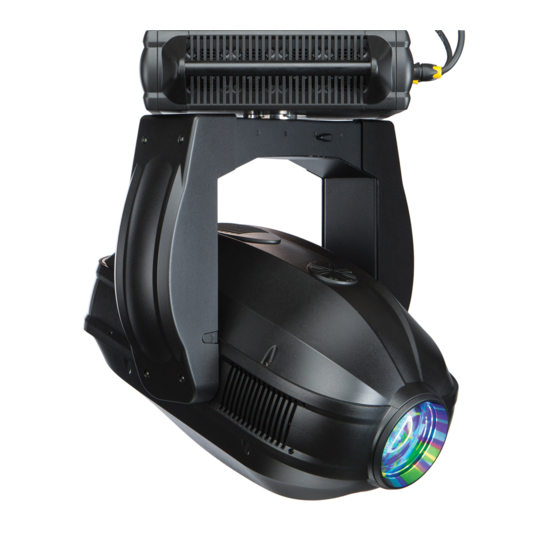
❋ VARI LITE - VL4000 S UMINAIRE ERVICE ANUAL Components External Luminaire Components The following illustration shows the external luminaire components and controls. Head Assembly Houses color system, gobos, animation Backcap Assembly wheels, strobe, iris and zoom lens mechanisms Provides access to lamp for replacement and provides controls for beam adjustment. -
Page 27: Head And Yoke Components
OMPONENTS EAD AND OMPONENTS Head and Yoke Components The following illustration shows the major sub-assemblies which are located in the luminaire head and yoke assemblies. Shutter/Gobo/Animation Assembly Head Cover (attached by tether) Contains two rotating gobo / effects wheels, four-blade shutter mechanism, two rotating animation sheels, and iris mechanism Color Module Assembly Contains fixed color wheels,... -
Page 28: Enclosure Components
❋ VARI LITE - VL4000 S UMINAIRE ERVICE ANUAL Enclosure Components The following illustration shows the major sub-assemblies which are located in the luminaire enclosure assembly. (Yoke and head assemblies not shown for clarity.) Enclosure Top Covers Pan Tube Assembly 36 VDC / Low-Voltage Power Supply Pan Motor Assembly... -
Page 29: Chapter 2. Maintenance & Service
HAPTER Maintenance & Service This chapter contains test, service, and standard maintenance procedures. • Troubleshooting • Routine Maintenance Procedures • Service Procedures WARNING: All maintenance procedures are to be performed with power removed from the luminaire. Never remove cover or backcap while lamp is in oper- ation. -
Page 30: Troubleshooting
❋ VARI LITE - VL4000 S UMINAIRE ERVICE ANUAL Troubleshooting Error Messages If a problem occurs during luminaire calibration, at the end of the calibration sequence the Menu Display will cycle through any applicable error message(s) until the end of the list is reached. To review the error messages again, it will be necessary to access them using the Status function. -
Page 31: Troubleshooting Guide
ROUBLESHOOTING ROUBLESHOOTING UIDE Troubleshooting Guide If a problem is suspected, try recalibrating the luminaire to prompt an error message. If a problem is suspected, first try recalibrating the luminaire to prompt an error message (refer to “Error Messages” on page 10). - Page 32 ❋ VARI LITE - VL4000 S UMINAIRE ERVICE ANUAL Message Symptom Description Possible Cause/Remedy Erratic control of lumi- DMX Termination No DMX termination or termination not correct... naire - check for DMX terminator. - Luminaire DMX address does not match console patch.
-
Page 33: Routine Maintenance Procedures Lamp Removal And Installation
OUTINE AINTENANCE ROCEDURES EMOVAL AND NSTALLATION Routine Maintenance Procedures WARNING: As with any repairs or maintenance to VARI❋LITE luminaires, service should only be performed by a trained and qualified service technician or at an Authorized VARI❋LITE Service facility. Lamp Removal and Installation WARNING: Disconnect fixture before relamping. - Page 34 ❋ VARI LITE - VL4000 S UMINAIRE ERVICE ANUAL Step 5. To remove lamp, grasp lamp base by hand, twist lamp counter-clockwise until lamp’s tabs align with slots in lamp socket (see Figure 2-2 on page 14 for more information), and remove lamp by pulling it straight out of socket.
- Page 35 OUTINE AINTENANCE ROCEDURES EMOVAL AND NSTALLATION Step 11. Disengage tilt lock to allow luminaire head to move freely. Step 12. Align lamp as needed. 02.97 04.001 0 A Note: All procedures are done with the power completely removed. Adhere to all warnings in this manual.
-
Page 36: Fixed Color Wheel Filter Removal And Installation
❋ VARI LITE - VL4000 S UMINAIRE ERVICE ANUAL Fixed Color Wheel Filter Removal and Installation To remove and replace fixed color filters: Step 1. Before removing power from luminaire, move Edge towards front of luminaire with control console or via luminaire menu system*. Note: *With DMX removed, hold Left and Right arrow keys to move edge to front of luminaire. - Page 37 OUTINE AINTENANCE ROCEDURES IXED OLOR HEEL ILTER EMOVAL AND NSTALLATION CAUTION: Wear protective gloves or other protective covering while handling filters to avoid leaving fingerprints. Filters are extremely fragile and can break if not handled carefully. If dirty, clean with isopropyl alcohol and a soft, lint-free cloth. Note: For standard fixed color filters, refer to “Fixed Color Wheel 1”...
- Page 38 ❋ VARI LITE - VL4000 S UMINAIRE ERVICE ANUAL Step 6. Install replacement filter into slot. Note orientation of fixed color filter as indicated in Figure 2-6. Make sure filter is inserted and secured by fixed color wheel retaining clip as shown in Figure 2-6.
-
Page 39: Rotating Gobo Removal And Installation
OUTINE AINTENANCE ROCEDURES OTATING EMOVAL AND NSTALLATION Rotating Gobo Removal and Installation CAUTION: VL4000 Spot Luminaires accept glass gobos only. Use of metal gobos in these luminaires may damage gobo assembly and will void the luminaire warranty. To remove and replace rotating gobos: Step 1. - Page 40 ❋ VARI LITE - VL4000 S UMINAIRE ERVICE ANUAL Note: For the standard load of rotating gobos, refer to “Rotating Gobo Wheel 1” on page 32 “Rotating Gobo Wheel 2” on page 33 Step 4. At rotating gobo wheel, slowly rotate wheel by hand until gobo to be removed is visible on assembly.
- Page 41 OUTINE AINTENANCE ROCEDURES OTATING EMOVAL AND NSTALLATION Retaining Tabs Rotating Gobo Assembly (Retaining clips need to be (gear side towards front of seated in pins but are not luminaire) used to aid in removal) Do not touch glass with bare fingers. CAUTION: Handle by gobo carrier only.
-
Page 42: Animation Wheels Removal And Installation
❋ VARI LITE - VL4000 S UMINAIRE ERVICE ANUAL Animation Wheels Removal and Installation To remove and replace animation wheels: Step 1. Before removing power from luminaire, move Edge towards front of luminaire with control console or via luminaire menu system. WARNING: Remove power from luminaire and allow luminaire to cool completely before performing this procedure. - Page 43 OUTINE AINTENANCE ROCEDURES NIMATION HEELS EMOVAL AND NSTALLATION Step 4. Loosen screw on bulkhead (also used as a stop) so animation arm can swing out. Step 5. Loosen idler pulley closest to motor. Step 6. Remove one screw from belt bearing on outside of frame. CAUTION: Be careful not to lose belt bearing, washer, screw or post.
-
Page 44: Cleaning Optical Lenses And Filters
❋ VARI LITE - VL4000 S UMINAIRE ERVICE ANUAL Cleaning Optical Lenses and Filters WARNING: Remove power from luminaire before performing maintenance. WARNING: Acetone is a harsh cleaning agent and solvent. Acetone is very flammable. Please handle acetone according to manufacturer’s safety instructions and precautions. The front lens, optics/color filters, and reflector may require cleaning after extended use. -
Page 45: Service Procedures
ERVICE ROCEDURES PPER NCLOSURE OVERS EMOVAL Service Procedures WARNING: As with any repairs or maintenance to VARI❋LITE luminaires, service should only be performed by a trained and qualified service technician or at an Authorized VARI❋LITE Service facility. Upper Enclosure Covers Removal Vari-Lite Part No: 21.9704.0850 (Connector side and Display side) To remove the upper enclosure covers: WARNING: Remove power from luminaire and allow luminaire to cool completely before... -
Page 46: Pfc Insulating Duct
❋ VARI LITE - VL4000 S UMINAIRE ERVICE ANUAL PFC Insulating Duct Vari-Lite Part No: 10.9704.0874 (PFC Insulating Duct) Vari-Lite Part No: 10.9704.1835 (Air Seal) Note: There are two versions of the duct. Original version mounts with 4 screws. Current version mounts with only 2 screws. -
Page 47: Lamp Driver Insulation Duct Removal
ERVICE ROCEDURES RIVER NSULATION EMOVAL Lamp Driver Insulation Duct Removal Vari-Lite Part No: 10.9704.1857 (Lamp Driver Insulation Duct) Note: There are two versions of the duct. Original version mounts with 3 screws. Current version will mount with only 2. Note: The top foam air seal is not part of the duct. If damaged, replace the air seal. Refer to “Lamp Driver Insulation Duct Air Seal Replacement”... -
Page 48: Lamp Driver Insulation Duct Air Seal Replacement
❋ VARI LITE - VL4000 S UMINAIRE ERVICE ANUAL Lamp Driver Insulation Duct Air Seal Replacement Vari-Lite Part No: 10.9704.1835 (Air Seal) To replace lamp driver insulation duct air seal: Step 1. Remove required upper enclosure cover following the procedure described in “Upper Enclosure Covers Removal”... -
Page 49: Main Control Board (Mcb)
(MCB) ERVICE ROCEDURES ONTROL OARD Main Control Board (MCB) Vari-Lite Part No: 21.9704.0880 To remove MCB: Step 1. Remove display side upper enclosure cover following the procedure described in “Upper Enclosure Covers Removal” on page Step 2. Remove Lamp Driver Insulation Duct following the procedure described in “Lamp Driver Insulation Duct Removal”... - Page 50 ❋ VARI LITE - VL4000 S UMINAIRE ERVICE ANUAL Step 5. Using ¼" wrench, remove 2 x 6-32 x 13/16" Standoffs at MCB. Standoffs Mounting Bracket Note: Drawing exploded and some components removed for clarity. Step 6. Carefully tilt MCB in towards the lamp driver. Step 7.
-
Page 51: Lamp Driver
ERVICE ROCEDURES RIVER Lamp Driver Vari-Lite Part No: 69.9704.1400 Note: There are two different versions of hardware mounting these Lamp Drivers. They QTY in () is for the older spot versions. To replace the lamp driver: Step 1. Remove display side upper enclosure cover following the procedure described in “Upper Enclosure Covers Removal”... -
Page 52: Pan Encoder Pcb
❋ VARI LITE - VL4000 S UMINAIRE ERVICE ANUAL Pan Encoder PCB Vari-Lite Part No: 17.9704.0910 To replace pan encoder PCB: Step 1. Remove both enclosure covers following the procedure described in “Upper Enclosure Covers Removal” on page Step 2. At pan encoder, disconnect wiring harness. Note: Drawing exploded and some Pan Bearing /... -
Page 53: Pan Motor Assembly
ERVICE ROCEDURES OTOR SSEMBLY Pan Motor Assembly Vari-Lite Part No: 22.9704.3820 Note: There are two different mounts for pan motor assemblies. On current versions, follow steps in this section. If an older unit, that does not have a notch in motor mounting plate on lamp driver side, follow instructions to replace pan belt. - Page 54 ❋ VARI LITE - VL4000 S UMINAIRE ERVICE ANUAL Step 9. Remove 2 x 8-32 x ¾" PPZ SEMS screws and remove belt tension roller bridge and rollers. Note: Drawing exploded and some components removed for clarity. Pan Motor Tension Roller Bridge Assembly Pan Belt Step 10.
-
Page 55: Pfc
: PFC ERVICE ROCEDURES Vari-Lite Part No: 69.9704.2450 Note: There are two different versions of hardware mounting the PFC. They QTY in () is for the older spot versions. To replace PFC: Step 1. Remove connector side upper enclosure cover following the procedure described in “Upper Enclosure Covers Removal”... -
Page 56: Pan Driver Board
❋ VARI LITE - VL4000 S UMINAIRE ERVICE ANUAL Pan Driver Board Vari-Lite Part No: 24.9704.1907 To remove pan driver board: Step 1. Remove both upper enclosure covers following the procedure described in “Upper Enclosure Covers Removal” on page Step 2. At pan driver board, disconnect all wiring from board. Step 3. -
Page 57: Low Voltage Supply (Lvs)
(LVS) ERVICE ROCEDURES OLTAGE UPPLY Low Voltage Supply (LVS) Vari-Lite Part No: 69.9704.0300 To replace LVS: Step 1. Remove both upper enclosure covers following the procedure described in “Upper Enclosure Covers Removal” on page Step 2. Remove pan driver board following the procedure described in “Pan Driver Board”... -
Page 58: Upper Enclosure Fan
❋ VARI LITE - VL4000 S UMINAIRE ERVICE ANUAL Upper Enclosure Fan Vari-Lite Part No: 22.9704.1850 Note: This part number is a service only item and differs from the drawing. It consists of all parts (fan, rubber fan mounts, and washers) needed to change one (1) fan in the upper enclosure. The upper enclosure has four (4) fans. -
Page 59: Neutrik True One Ac Input Connector
AC I ERVICE ROCEDURES EUTRIK NPUT ONNECTOR Neutrik True One AC Input Connector Vari-Lite Part No: 25.9704.0830 To replace Neutrik True One AC input connector: Step 1. Remove connector side enclosure cover following the procedure described in “Upper Enclosure Covers Removal” on page Step 2. -
Page 60: Dmx Pcb Assembly
❋ VARI LITE - VL4000 S UMINAIRE ERVICE ANUAL DMX PCB Assembly Vari-Lite Part No: 24.9664.4895 To replace DMX PCB assembly: Step 1. Remove connector side enclosure cover following the procedure described in “Upper Enclosure Covers Removal” on page Step 2. Disconnect wiring from DMX PCB. Step 3. -
Page 61: Display Overlay
ERVICE ROCEDURES ISPLAY VERLAY Display Overlay Vari-Lite Part No: 11.9704.0846 To replace display overlay: Step 1. Remove both enclosure covers following the procedure described in “Upper Enclosure Covers Removal” on page Step 2. Remove 8 x 6-32 x 3/8" PFSS-B screws and remove front cover. Display Note: Overlay... -
Page 62: Usb Port
❋ VARI LITE - VL4000 S UMINAIRE ERVICE ANUAL USB Port Vari-Lite Part No: 46.9704.0853 To replace USB port: Step 1. Remove both enclosure covers following the procedure described in “Upper Enclosure Covers Removal” on page Step 2. Disconnect wiring from MCB (refer to information in “Main Control Board (MCB)”... -
Page 63: Upper Enclosure Air Filters (To Clean Or Replace)
ERVICE ROCEDURES PPER NCLOSURE ILTERS LEAN OR EPLACE Upper Enclosure Air Filters (To Clean or Replace) Vari-Lite Part No: 10.9704.1842 To remove, clean, and replace air filters: WARNING: Remove power from luminaire and allow luminaire to cool completely before performing this procedure. Failure to remove power from luminaire can result in serious injury or death! Step 1. -
Page 64: Pan Belt
❋ VARI LITE - VL4000 S UMINAIRE ERVICE ANUAL Pan Belt Note: This procedure is also for old-style pan motor assemblies (with no notch) as described in “Pan Motor Assembly” on page Vari-Lite Part No: 54.9698.0224 To remove pan belt or old-style pan motor assemblies (with no notch): Step 1. - Page 65 ERVICE ROCEDURES Step 5. Rotate enclosure to access 1 of the 4 ¼-20 x 2" SOC screws. ¼-20 x 2" SOC Screw (x4) Note: Spacer (x4) Drawing exploded and some components removed for clarity. Step 6. Using 5/32" Allen wrench, remove each screw and unthreaded spacer. Rotate the enclosure and remove all 4.
-
Page 66: Yoke Arm Covers Removal
❋ VARI LITE - VL4000 S UMINAIRE ERVICE ANUAL Yoke Arm Covers Removal Vari-Lite Part No: 22.9704.0732 (Spot) To remove yoke arm covers: WARNING: Remove power from luminaire and allow luminaire to cool completely before performing this procedure. Failure to remove power from luminaire can result in serious injury or death! Step 1. -
Page 67: Yoke Base Cover
ERVICE ROCEDURES OVER Yoke Base Cover Vari-Lite Part No: 10.9704.1733 To remove yoke base cover: Step 1. Remove both yoke arm covers following the procedure described in “Yoke Arm Covers Removal” on page Step 2. At each yoke side, remove 2 per side 8-32 x 5/16" PPZ screws and remove yoke base cover. Note: Drawing exploded and some components removed for clarity. -
Page 68: Igniter Assembly
❋ VARI LITE - VL4000 S UMINAIRE ERVICE ANUAL Igniter Assembly Vari-Lite Part No: 24.9704.1126 To replace igniter assembly: Step 1. Remove tilt lock side yoke arm cover following the procedure described in “Yoke Arm Covers Removal” on page Step 2. At igniter, remove 4 x 6-32 terminal screws and remove input and output wiring. Note these screws MUST be used to attach wiring. -
Page 69: Tilt Lock Arm Assembly
ERVICE ROCEDURES SSEMBLY Tilt Lock Arm Assembly Vari-Lite Part No: 10.9704.1751 (Rod) Vari-Lite Part No: 10.9704.0753 (Lever, x2) Vari-Lite Part No: 10.9704.1752 (Locking Pin) To replace tilt lock assembly or its parts: Step 1. Remove tilt lock side yoke arm cover following the procedure described in “Yoke Arm Covers Removal”... -
Page 70: Tilt Driver
❋ VARI LITE - VL4000 S UMINAIRE ERVICE ANUAL Tilt Driver Vari-Lite Part No: 24.9704.1908 To replace the tilt driver: Step 1. Remove yoke arm cover opposite tilt lock following the procedure described in “Yoke Arm Covers Removal” on page Step 2. -
Page 71: Tilt Encoder
ERVICE ROCEDURES NCODER Tilt Encoder Vari-Lite Part No: 17.9704.1911 Note: After performing this procedure, the tilt center position will need to be reset via the luminaire’s menu system. Refer to the luminaire’s user’s manual for procedure. To replace the tilt encoder: Step 1. -
Page 72: Tilt Motor Assembly
❋ VARI LITE - VL4000 S UMINAIRE ERVICE ANUAL Tilt Motor Assembly Vari-Lite Part No: 21.9704.0764 To remove tilt motor assembly: Step 1. Remove yoke arm cover opposite tilt lock following the procedure described in “Yoke Arm Covers Removal” on page Step 2. - Page 73 ERVICE ROCEDURES OTOR SSEMBLY 3) Tighten screw to hold roller with loose tension. Tilt Motor Assembly Tension Roller Note: Drawing exploded and some components removed for clarity. b. Type 2 1) To loose belt tension, loosen 3 x #8 KEPS nuts and slide tensioner toward motor Step 4.
-
Page 74: Tilt Belt
❋ VARI LITE - VL4000 S UMINAIRE ERVICE ANUAL Tilt Belt Vari-Lite Part No: 54.9698.0224 To remove and replace tilt belt: Step 1. Remove yoke arm cover opposite tilt lock following the procedure described in “Yoke Arm Covers Removal” on page Step 2. - Page 75 ERVICE ROCEDURES b. Type 2 1) To loose belt tension, loosen 3 x #8 KEPS nuts and slide tensioner toward motor. 2) Remove 4 x 6-32 x 3/8" PPZ SEMS screws and remove motor assembly Step 6. Remove belt. Step 7. Replace in reverse. Follow belt tension procedure as described in “Tilt Motor Assembly”...
-
Page 76: Yoke Assembly
❋ VARI LITE - VL4000 S UMINAIRE ERVICE ANUAL Yoke Assembly Vari-Lite Part No: 22.9704.0705 Note: This procedure is for replacing the yoke assembly only. You will transfer several parts to the replacement yoke assembly. To replace the yoke assembly: Step 1. - Page 77 ERVICE ROCEDURES SSEMBLY Step 9. At each side, remove 2 (4 total) 8-32 KEPS nut and remove tilt bearing clamp plate. Tilt Bearing Clamp Plate Tilt Bearing Clamp Plate 8-32 KEPS Nuts 8-32 KEPS Nuts Yoke Assembly Head Assembly Pan Tube Assembly 10-32 x 5/8"...
- Page 78 ❋ VARI LITE - VL4000 S UMINAIRE ERVICE ANUAL Step 11. On inside of yoke at tilt motor side, remove 1 8-32 x 5/16" PPZ screw (nearest outside of yoke) and loosen 1 8-32 x 5/16" PPZ screw nearest pan tube and slide pan safety plate away from pan tube.
-
Page 79: Luminaire Head Covers Removal
ERVICE ROCEDURES UMINAIRE OVERS EMOVAL Luminaire Head Covers Removal Vari-Lite Part No: 22.9704.0670 WARNING: Remove power from luminaire and allow luminaire to cool completely before performing this procedure. Failure to remove power from luminaire can result in serious injury or death! Note: Top head cover is side with serial number on yoke. -
Page 80: Front Side Rail Covers
❋ VARI LITE - VL4000 S UMINAIRE ERVICE ANUAL Front Side Rail Covers Vari-Lite Part No: 10.9704.0672 Input Air Filter Vari-Lite Part No: 10.9704.0641 To remove front side rail covers and input air filters: Step 1. Remove both luminaire head covers following the procedure described in “Luminaire Head Covers Removal”... -
Page 81: Rear Side Rail Cover Removal
ERVICE ROCEDURES OVER EMOVAL Rear Side Rail Cover Removal Vari-Lite Part No: 10.9704.0673 To remove side rail covers: Step 1. Remove both head covers following procedure in “Luminaire Head Covers Removal” on page Step 2. Remove 4 x 6-32 x 3/8" PPB screws and remove cover. Rear Cover Rear Rail Cover Screw... -
Page 82: Rear Cover Removal
❋ VARI LITE - VL4000 S UMINAIRE ERVICE ANUAL Rear Cover Removal Vari-Lite Part No: 10.9704.0671 To remove rear cover: Step 1. Remove 2 x 6-32 x 5/8" PPB screws at outside and 6 x 6-32 x 3/8" PPB screws around inside. -
Page 83: Color Assembly Removal
ERVICE ROCEDURES OLOR SSEMBLY EMOVAL Color Assembly Removal Vari-Lite Part No: 21.9704.4400 To remove color assembly: Step 1. Run the edge (focus) mechanism to the full forward (toward the lenses) position. This can be done using a console by sending a DMX value of 100% (65535 decimal) on the 16-bit edge channel. -
Page 84: Gobo / Shutter / Animation Assembly Removal
❋ VARI LITE - VL4000 S UMINAIRE ERVICE ANUAL Gobo / Shutter / Animation Assembly Removal Vari-Lite Part No: 21.9704.0200 To remove gobo assembly: Step 1. Remove color assembly following the procedure described in “Color Assembly Removal” on page Step 2. At Driver Board C Kurly Loc cable tie, disconnect DC power to board C and shutter and COM into board C and out to board F. -
Page 85: Optics Assembly Removal
ERVICE ROCEDURES PTICS SSEMBLY EMOVAL Optics Assembly Removal Vari-Lite Part No: 21.9704.0150 (Initial Models) Vari-Lite Part No: 21.9704.1150 (Models with Single Divergence) To remove the optics assembly: Step 1. Remove both front side rail covers following the procedure described in “Front Side Rail Covers”... -
Page 86: Inlet Fan
❋ VARI LITE - VL4000 S UMINAIRE ERVICE ANUAL Inlet Fan Vari-Lite Part No: 23.9704.1002 To replace inlet fan: Step 1. Remove tilt lock side front side rail cover following the procedure described in “Front Side Rail Covers” on page Step 2. -
Page 87: Power Distribution Board
ERVICE ROCEDURES OWER ISTRIBUTION OARD Power Distribution Board Vari-Lite Part No: 23.9704.2909 To remove power distribution board: Step 1. Remove tilt lock side rear side rail cover following the procedure described in “Rear Side Rail Cover Removal” on page Step 2. At power distribution board, disconnect all wiring. Step 3. -
Page 88: Base Lamp Fan
❋ VARI LITE - VL4000 S UMINAIRE ERVICE ANUAL Base Lamp Fan Vari-Lite Part No: 23.9704.0003 To replace base lamp fan: Step 1. Remove power distribution board following the procedure described in “Power Distribution Board” on page Step 2. At fan, disconnect wiring harness. Step 3. -
Page 89: Tip Lamp Fan
ERVICE ROCEDURES Tip Lamp Fan Vari-Lite Part No: 23.9704.0003 To replace tip lamp fan: Step 1. Remove non tilt lock side rear side rail cover following the procedure described in “Rear Side Rail Cover Removal” on page Step 2. At fan, disconnect wiring harness. Step 3. -
Page 90: Uv Glass Assembly
❋ VARI LITE - VL4000 S UMINAIRE ERVICE ANUAL UV Glass Assembly Vari-Lite Part No: 22.9704.0630 To replace UV glass assembly: Step 1. Remove color assembly following the procedure described in “Color Assembly Removal” on page Step 2. Remove 4 x 4-40 x ¼" PFZ screws and remove UV assembly. Note: UV Glass Assembly Drawing exploded and some... -
Page 91: Bottom Exhaust Fin Assembly
ERVICE ROCEDURES OTTOM XHAUST SSEMBLY Bottom Exhaust Fin Assembly Vari-Lite Part No: 22.9704.1620 To remove bottom exhaust fin assembly: Step 1. Remove bottom head cover following the procedure described in “Luminaire Head Covers Removal” on page Step 2. Remove color bulkhead assembly following the procedure described in “Color Assembly Removal”... -
Page 92: Top Exhaust Fin Assembly
❋ VARI LITE - VL4000 S UMINAIRE ERVICE ANUAL Top Exhaust Fin Assembly Vari-Lite Part No: 22.9704.1620 To remove top exhaust fin assembly: Step 1. Remove top head cover following the procedure described in “Luminaire Head Covers Removal” on page Step 2. -
Page 93: Reflector Assembly
ERVICE ROCEDURES EFLECTOR SSEMBLY Reflector Assembly Vari-Lite Part No: 21.9704.0619 To replace reflector assembly: Step 1. Remove lamp following the procedure described in “Lamp Removal and Installation” on page Step 2. Remove rear cover following the procedure described in “Rear Cover Removal” on page Step 3. -
Page 94: Retro Reflector Assembly
❋ VARI LITE - VL4000 S UMINAIRE ERVICE ANUAL Retro Reflector Assembly Vari-Lite Part No: 42.9704.0151 To replace retro reflector assembly: Step 1. Remove reflector assembly following the procedure described in “Reflector Assembly” on page Step 2. Loosen, but do not remove, 4 x 6-32 x 3/16" PPZ screws, pivot retainer clips and remove retro reflector assembly. -
Page 95: Ellipsoidal Reflector
ERVICE ROCEDURES LLIPSOIDAL EFLECTOR Ellipsoidal Reflector Vari-Lite Part No: 42.9704.0150 To replace ellipsoidal reflector: Step 1. Remove reflector assembly following the procedure described in “Reflector Assembly” on page Step 2. Loosen 4 x 6-32 x 3/16" PPZ screws, pivot retainer clips and remove reflector. Retainer Clip Screw (x4) Ellipsoidal Reflector Note:... -
Page 96: Lamp Socket
❋ VARI LITE - VL4000 S UMINAIRE ERVICE ANUAL Lamp Socket Vari-Lite Part No: 71.8101.0050 To replace lamp socket: Step 1. Remove lamp following the procedure described in “Lamp Removal and Installation” on page Step 2. Remove rear cover following the procedure described in “Rear Cover Removal”... -
Page 97: Optics Assembly Components
ERVICE ROCEDURES PTICS SSEMBLY OMPONENTS Optics Assembly Components Vari-Lite Part No: 21.9704.0150 Vari-Lite Part No: 21.9704.1150 (with single divergence) Note: The following procedures in this section may require the assembly removed from the luminaire. If indicated in the procedure, follow the removal instructions described in “Optics Assembly Removal”... - Page 98 ❋ VARI LITE - VL4000 S UMINAIRE ERVICE ANUAL c. Yellow/Black/Green/Blue - Bottom inlet fan d. Sensor 1 - 5 1) 1 - ES1 P DIV - Prism Diversion Sensor 2) 2 - ES2 P ARM - Prism Arm Sensor 3) 3 - ES3 P ROT - Prism Rotate/Index Sensor 4) 4 - ES4 F DIV - Frost Diversion Sensor (21.9704.0150 ONLY) 5) 5 - ES5 F ARM - Frost Arm Sensor...
-
Page 99: Driver Board F
ERVICE ROCEDURES PTICS SSEMBLY OMPONENTS Driver Board F Vari-Lite Part No: 24.9704.2901 To replace driver board F: Step 1. Remove 3 x 4-40 x 3/8" PPZ SEMS screws that mount driver board clamp and remove clamp. Note: Drawing exploded and some components removed for clarity. -
Page 100: Frost Divergence Sensor
❋ VARI LITE - VL4000 S UMINAIRE ERVICE ANUAL Frost Divergence Sensor Vari-Lite Part No: 25.9678.0020 (on 21.9704.0150 ONLY) To replace frost divergence sensor: Step 1. At sensor, disconnect inline wiring connector Step 2. At driver board E, remove 3 x 6-32 x 3/8" PPZ SEMS screws that hold driver board mount. Step 3. -
Page 101: Prism Divergence Sensor
ERVICE ROCEDURES PTICS SSEMBLY OMPONENTS Prism Divergence Sensor Vari-Lite Part No: 25.9678.0020 To replace prism divergence sensor: Step 1. At sensor, disconnect inline wiring connector. Step 2. At driver board E, remove 3 x 6-32 x 3/8" PPZ SEMS screws that hold driver board mount. Step 3. -
Page 102: Zoom Or Compensation Sensor
❋ VARI LITE - VL4000 S UMINAIRE ERVICE ANUAL Zoom or Compensation Sensor Vari-Lite Part No: 25.9678.0020 To replace zoom or compensation sensor: Note: Refer to “VL4000 Zoom Spot Assembly” on page 171 for drawing. Step 1. At sensor, disconnect inline wiring connector. Step 2. -
Page 103: Prism Arm Sensor
ERVICE ROCEDURES PTICS SSEMBLY OMPONENTS Prism Arm Sensor Vari-Lite Part No: 25.9678.0020 To replace prism arm sensor: Step 1. At sensor, disconnect inline wiring connector. Step 2. Remove 2 x 4-40 x ¼" PPZ SEMS screws and remove sensor. Note: Drawing exploded and some components removed for clarity. -
Page 104: Frost Arm Sensor
❋ VARI LITE - VL4000 S UMINAIRE ERVICE ANUAL Frost Arm Sensor Vari-Lite Part No: 25.9678.0020 To replace frost arm sensor: Step 1. At sensor, disconnect inline wiring connector. Step 2. Remove 2 x 4-40 x ¼" PPZ SEMS screws and remove sensor. 4-40 x 1/4"... -
Page 105: Frost Motor Or Motor Stabilizer
ERVICE ROCEDURES PTICS SSEMBLY OMPONENTS Frost Motor or Motor Stabilizer Vari-Lite Part No: 44.9676.0117 (Frost Motor) Vari-Lite Part No: 21.9698.0330 (Motor Stabilizer) To replace the frost motor or motor stabilizer: Step 1. Loosen 2 x 6-32 x 3/16" cone set screws and remove frost arm (apply heat as necessary and reapply Loctite 242 when replacing). -
Page 106: Frost Divergence Motor
❋ VARI LITE - VL4000 S UMINAIRE ERVICE ANUAL Frost Divergence Motor Vari-Lite Part No: 44.9698.0147 To replace frost divergence motor: Step 1. At lead screw, remove 2 #8 KEPS nuts. Step 2. Using slot in end of lead screw, thread out of motor Step 3. -
Page 107: Prism Index Sensor
ERVICE ROCEDURES PTICS SSEMBLY OMPONENTS Prism Index Sensor Vari-Lite Part No: 17.9704.0904 To replace prism index sensor: Step 1. Disconnect wiring from sensor. Step 2. Remove 2 x 2-56 x ¼" PPZ screws and remove sensor*. 2-56 x 1/4" PPZ Screw (x2) Prism Index Sensor Teflon Washer (x2) -
Page 108: Prism Rotate Motor
❋ VARI LITE - VL4000 S UMINAIRE ERVICE ANUAL Prism Rotate Motor Vari-Lite Part No: 44.9687.1218 To replace prism rotate motor: Step 1. Disconnect wiring. Step 2. Remove 2 x 4-40 x 3/8" PPZ SEMS screws. Note: Drawing exploded and some components removed for clarity. -
Page 109: Prism Arm Motor & Stabilizer
ERVICE ROCEDURES PTICS SSEMBLY OMPONENTS Prism Arm Motor & Stabilizer Vari-Lite Part No: 44.9698.1215 (Motor) Vari-Lite Part No: 21.9698.0330 (Motor Stabilizer) To replace the prism arm motor or motor stabilizer: Step 1. Disconnect wiring. Step 2. Remove prism arm assembly by loosening 2 x 6-32 x 3/16" cone set screws. Step 3. -
Page 110: Prism Divergence Motor
❋ VARI LITE - VL4000 S UMINAIRE ERVICE ANUAL Prism Divergence Motor Vari-Lite Part No: 44.9698.0147 To replace prism divergence motor: Step 1. Disconnect wiring. Step 2. At lead screw, remove 2 x #8 KEPS nut. Step 3. Using slot in end, thread lead screw out of motor. 4-40 x 1/4"... -
Page 111: Compensation Motor
ERVICE ROCEDURES PTICS SSEMBLY OMPONENTS Compensation Motor Vari-Lite Part No: 44.9686.0164 To replace compensation motor: Step 1. Disconnect wiring. Step 2. Apply localized heat of greater than 232 Degrees C (450 Degrees F) to joint of lead screw and actuator spacer to loosen thread lock (Loctite 272). Compensation Motor Note: 6-32 x 1/4"... -
Page 112: Zoom Motor & Stabilizer
❋ VARI LITE - VL4000 S UMINAIRE ERVICE ANUAL Zoom Motor & Stabilizer Vari-Lite Part No: 44.9698.1215 (Motor) Vari-Lite Part No: 21.9698.0330 (Motor Stabilizer) To replace the zoom motor or motor stabilizer: Step 1. Disconnect wiring. Step 2. Remove 1 x 4-40 x 3/8" PFZ screw and remove stabilizer*. Note: * If just replacing the motor stabilizer, replace in reverse order - do not continue to next steps. -
Page 113: Zoom Belt
ERVICE ROCEDURES PTICS SSEMBLY OMPONENTS Zoom Belt Vari-Lite Part No: 54.9704.0135 To replace the zoom belt: Step 1. Remove 1 x 6-32 x ¼" PPZ SEMS screw clamping belt to zoom lens. Note: Drawing exploded and some components removed for clarity. 6-32 x 1/4"... -
Page 114: Gobo/Shutter/Animation Assembly Components
❋ VARI LITE - VL4000 S UMINAIRE ERVICE ANUAL Gobo/Shutter/Animation Assembly Components Vari-Lite Part No: 21.9704.0200 Note: The following procedures in this section may require the assembly removed from the luminaire. If indicated in the procedure, follow the removal instructions described in “Gobo / Shutter / Animation Assembly Removal”... - Page 115 ERVICE ROCEDURES HUTTER NIMATION SSEMBLY OMPONENTS b. COM in and out - each labeled motor driver (note, does not matter which goes in which connector on board). c. Sensor 1 - 5 1) 1 - CS1 G INDEX 2 - Gobo Wheel 2 Index Sensor 2) 2 - CS2 G ROT 2 - Gobo Wheel 2 Wheel Sensor 3) 3 - CS3 G ROT 1 - Gobo Wheel 1 Wheel Sensor 4) 4 - CS4 G INDEX 1 - Gobo Wheel 1 Index Sensor...
-
Page 116: Driver Board D
❋ VARI LITE - VL4000 S UMINAIRE ERVICE ANUAL Driver Board D Vari-Lite Part No: 24.9704.2901 To replace driver board D: Step 1. Remove 3 x 4-40 x 3/8" PPZ SEMS screws that mount driver board clamp and remove clamp. Note: Drawing exploded and some components removed for clarity. - Page 117 ERVICE ROCEDURES HUTTER NIMATION SSEMBLY OMPONENTS e. Motor 1 - 4 1) 1 - DM1 FX INDEX 2 - Animation Wheel 2 Index Motor 2) 2 - DM2 FX INDEX 1 - Animation Wheel 1 Index Motor 3) 3 - DM3 FX ARM 1 - Animation Wheel 1 Arm Motor 4) 4 - DM4 FX ARM 2 - Animation Wheel 2 Arm Motor Step 3.
-
Page 118: Shutter Driver Board (9 Way)
❋ VARI LITE - VL4000 S UMINAIRE ERVICE ANUAL Shutter Driver Board (9 Way) Vari-Lite Part No: 24.9704.1902 To replace shutter driver board (9 way): Step 1. Remove Gobo / Shutter / Animation Assembly following procedure in “Gobo / Shutter / Animation Assembly Removal”... - Page 119 ERVICE ROCEDURES HUTTER NIMATION SSEMBLY OMPONENTS Step 3. Remove 3 x M3 .5 x 10 mm LG, PPZ SEMS screws through cable saddles and 3 x M3 .5 x 6 mm LG, PPZ SEMS screws and remove board. Note: Drawing exploded and some components removed for clarity.
-
Page 120: Iris Motor
❋ VARI LITE - VL4000 S UMINAIRE ERVICE ANUAL Iris Motor Vari-Lite Part No: 44.9704.0208 To replace iris motor: Step 1. Remove Gobo / Shutter / Animation Assembly following procedure in “Gobo / Shutter / Animation Assembly Removal” on page Step 2. -
Page 121: Iris Cable
ERVICE ROCEDURES HUTTER NIMATION SSEMBLY OMPONENTS Iris Cable Vari-Lite Part No: 54.9704.0292 (x 10.5-inches) To replace the iris cable: Step 1. Remove Gobo / Shutter / Animation Assembly following procedure in “Gobo / Shutter / Animation Assembly Removal” on page Step 2. -
Page 122: Animation Wheel 1 & 2 Assembly
❋ VARI LITE - VL4000 S UMINAIRE ERVICE ANUAL Animation Wheel 1 & 2 Assembly Vari-Lite Part No: 21.9704.0351 (Wheel #1) Vari-Lite Part No: 21.9704.0352 (Wheel #2) To replace animation wheels 1 and 2 assemblies: Note: This procedure is for removing either animation wheel assembly. To remove and replace just the animation wheels, refer to “Animation Wheels Removal and Installation”... -
Page 123: Animation Wheel Arm Sensor
ERVICE ROCEDURES HUTTER NIMATION SSEMBLY OMPONENTS Animation Wheel Arm Sensor Vari-Lite Part No: 21.9687.2500 To replace animation wheel sensor: Step 1. Disconnect wiring harness from sensor. Step 2. Remove 2 x 4-40 x ¼" PPZ SEMS screws and remove sensor. Animation Wheel Motor Assembly Shown Note: Drawing exploded and some... -
Page 124: Animation Index Belt
❋ VARI LITE - VL4000 S UMINAIRE ERVICE ANUAL Animation Index Belt Vari-Lite Part No: 54.9704.0392 Note: There are at least two different versions in the field. To replace animation wheel index belt: Step 1. Remove animation wheel assembly following procedure in “Animation Wheel 1 &... -
Page 125: Animation Index Motor & Arm Belt
ERVICE ROCEDURES HUTTER NIMATION SSEMBLY OMPONENTS Animation Index Motor & Arm Belt Vari-Lite Part No: 44.9704.1213 (Animation Index Motor) Vari-Lite Part No: 54.9704.1390 (Arm Belt) To replace the animation index motor or arm belt: Step 1. Remove animation wheel belt following procedure in “Animation Index Belt”... - Page 126 ❋ VARI LITE - VL4000 S UMINAIRE ERVICE ANUAL Step 4. Remove 4 x M3 x .5 x 4 mm PFZ screws and remove motor. Index Motor Note: Drawing exploded and some components removed for clarity. M3 x .5 x 4 mm PFZ Screw (x4) Step 5.
-
Page 127: Animation Index Sensors
ERVICE ROCEDURES HUTTER NIMATION SSEMBLY OMPONENTS Animation Index Sensors Vari-Lite Part No: 17.9704.0906 (x2) To replace animation index sensors: Step 1. Remove 2 x 2-56 x 3/8" PPZ screws that mount sensor board and connector clamp. Screws Connector Clamp Note: Drawing exploded and some components removed for clarity. -
Page 128: Gobo Wheel 1 Rotate Belt
❋ VARI LITE - VL4000 S UMINAIRE ERVICE ANUAL Gobo Wheel 1 Rotate Belt Vari-Lite Part No: 54.9704.0290 To remove gobo wheel 1 rotate belt: Step 1. Remove Gobo / Shutter / Animation Assembly following procedure in “Gobo / Shutter / Animation Assembly Removal”... -
Page 129: Gobo Wheel 1 Index Belt
ERVICE ROCEDURES HUTTER NIMATION SSEMBLY OMPONENTS Gobo Wheel 1 Index Belt Vari-Lite Part No: 54.9698.0002 To remove gobo wheel 1 index belt: Step 1. Remove Gobo / Shutter / Animation Assembly following procedure in “Gobo / Shutter / Animation Assembly Removal” on page Gobo Wheel 2 Gobo Wheel 1 Note:... -
Page 130: Gobo Wheel 2 Index Belt & Rotate Belt
❋ VARI LITE - VL4000 S UMINAIRE ERVICE ANUAL Gobo Wheel 2 Index Belt & Rotate Belt Vari-Lite Part No: 54.9704.0290 (Index Belt) Vari-Lite Part No: 54.9698.0002 (Rotate Belt) To replace gobo wheel 2 index belt or rotate belt: Step 1. Remove Animation Wheel 2 assembly following procedure in “Animation Wheel 1 &... - Page 131 ERVICE ROCEDURES HUTTER NIMATION SSEMBLY OMPONENTS Step 3. Remove top cooling duct by removing 3 x 4-20 x ¼" PFZ plastic thread cutting screws. Top Cooling Duct Note: Drawing exploded and some components removed for clarity. Step 4. At index sensor, remove 2 x 4-40 x ¼" PFZ screws and remove index sensor bracket. Gobo 2 Shaft Note: Drawing exploded and some...
-
Page 132: Gobo Wheel 2 Index Sensor
❋ VARI LITE - VL4000 S UMINAIRE ERVICE ANUAL Gobo Wheel 2 Index Sensor Vari-Lite Part No: 17.9704.0904 To replace gobo wheel 2 index sensor: Step 1. Remove Gobo / Shutter / Animation Assembly following procedure in “Gobo / Shutter / Animation Assembly Removal”... -
Page 133: Edge Motor Brackets And Support Brace Removal
ERVICE ROCEDURES HUTTER NIMATION SSEMBLY OMPONENTS Edge Motor Brackets and Support Brace Removal To remove edge motor brackets and support brace: Step 1. Remove Gobo / Shutter / Animation Assembly following procedure in “Gobo / Shutter / Animation Assembly Removal” on page Step 2. -
Page 134: Gobo Wheel 1 Index Motor
❋ VARI LITE - VL4000 S UMINAIRE ERVICE ANUAL Gobo Wheel 1 Index Motor Vari-Lite Part No: 44.9704.0217 To replace gobo wheel 1 index motor: Step 1. Remove Gobo / Shutter / Animation Assembly following procedure in “Gobo / Shutter / Animation Assembly Removal”... -
Page 135: Gobo Wheel 1 Rotate Motor
ERVICE ROCEDURES HUTTER NIMATION SSEMBLY OMPONENTS Gobo Wheel 1 Rotate Motor Vari-Lite Part No: 44.9704.0217 To replace gobo wheel 1 rotate motor: Step 1. Remove edge assembly following procedure in “Edge Motor Brackets and Support Brace Removal” on page 113. Step 2. -
Page 136: Gobo Wheel 2 Rotate Motor
❋ VARI LITE - VL4000 S UMINAIRE ERVICE ANUAL Gobo Wheel 2 Rotate Motor Vari-Lite Part No: 44.9704.0217 To replace gobo wheel 2 rotate motor: Step 1. Remove edge assembly following procedure in “Edge Motor Brackets and Support Brace Removal” on page 113. -
Page 137: Gobo Wheel 2 Index Motor
ERVICE ROCEDURES HUTTER NIMATION SSEMBLY OMPONENTS Gobo Wheel 2 Index Motor Vari-Lite Part No: 44.9704.0217 To replace gobo wheel 2 index motor: Step 1. Remove Gobo / Shutter / Animation Assembly following procedure in “Gobo / Shutter / Animation Assembly Removal” on page Step 2. -
Page 138: Gobo Wheel 1 Index Sensor And Wheel 1 Rotate Sensor
❋ VARI LITE - VL4000 S UMINAIRE ERVICE ANUAL Gobo Wheel 1 Index Sensor and Wheel 1 Rotate Sensor Vari-Lite Part No: 17.9704.0905 (Index Sensor) Vari-Lite Part No: 24.9678.3240 (Rotate Sensor) To replace gobo wheel 1 index sensor and rotate sensor: Step 1. -
Page 139: Gobo Wheel 2 Rotate Sensor
ERVICE ROCEDURES HUTTER NIMATION SSEMBLY OMPONENTS Gobo Wheel 2 Rotate Sensor Vari-Lite Part No: 24.9678.3240 To replace gobo wheel 2 rotate sensor: Step 1. Remove Gobo / Shutter / Animation Assembly following procedure in “Gobo / Shutter / Animation Assembly Removal” on page Step 2. -
Page 140: Animation Arm Motors 1 Or 2
❋ VARI LITE - VL4000 S UMINAIRE ERVICE ANUAL Animation Arm Motors 1 or 2 Vari-Lite Part No: 44.9704.0209 (Motor) Vari-Lite Part No: 21.9698.0330 (Motor Stabilizer) To replace animation arm motors 1 or 2: Step 1. Remove edge assembly following procedure in “Edge Motor Brackets and Support Brace Removal”... -
Page 141: Shutter Assembly & Belt
ERVICE ROCEDURES HUTTER NIMATION SSEMBLY OMPONENTS Shutter Assembly & Belt Vari-Lite Part No: 21.9704.1510 Vari-Lite Part No: 54.9704.1570 (Belt) Step 1. Remove edge assembly following procedure in “Edge Motor Brackets and Support Brace Removal” on page 113. Step 2. At driver board, disconnect DC input (Orange/Red/Black) and COM (SHTTR). Step 3. -
Page 142: Shutter Sensor
❋ VARI LITE - VL4000 S UMINAIRE ERVICE ANUAL Shutter Sensor Vari-Lite Part No: 24.9678.3240 To replace shutter sensor: Step 1. Remove Gobo / Shutter / Animation Assembly following procedure in “Gobo / Shutter / Animation Assembly Removal” on page Step 2. -
Page 143: Shutter Blade Motor
ERVICE ROCEDURES HUTTER NIMATION SSEMBLY OMPONENTS Shutter Blade Motor Vari-Lite Part No: 22.9704.1515 To replace shutter motor: Step 1. Remove Gobo / Shutter / Animation Assembly following procedure in “Gobo / Shutter / Animation Assembly Removal” on page Step 2. Remove shutter blade by removing 1 x 2-56 x ¼" PFZ screw through shutter into shutter pivot and remove pivot, keeping glide on pivot. -
Page 144: Shutter Rotate Motor
❋ VARI LITE - VL4000 S UMINAIRE ERVICE ANUAL Shutter Rotate Motor Vari-Lite Part No: 44.9687.1209 To replace shutter rotate motor: Step 1. Remove Gobo / Shutter / Animation Assembly following procedure in “Gobo / Shutter / Animation Assembly Removal” on page Step 2. -
Page 145: Iris Assembly
ERVICE ROCEDURES HUTTER NIMATION SSEMBLY OMPONENTS Iris Assembly Vari-Lite Part No: 22.9704.0275 To replace iris assembly: Step 1. Remove Gobo / Shutter / Animation Assembly following procedure in “Gobo / Shutter / Animation Assembly Removal” on page Step 2. Remove iris synchromesh cable following procedure in “Iris Cable”... -
Page 146: Color Assembly Components
❋ VARI LITE - VL4000 S UMINAIRE ERVICE ANUAL Color Assembly Components Vari-Lite Part No: 21.9704.4400 Note: The following procedures in this section may require the assembly removed from the luminaire. To remove the assembly follow the procedure described in “Color Assembly Removal”... - Page 147 ERVICE ROCEDURES OLOR SSEMBLY OMPONENTS 2) 2 - BM2 FIX 2 - Fixed Color Wheel 2 Motor 3) 3 - BM3 FIX 1 - Fixed Color Wheel 1 Motor 4) 4 - BM4 YEL - Yellow Motor Step 3. Remove 1 x 4-40 x ¼" PPZ SEMS screw and remove board. Step 4.
-
Page 148: Driver Board A
❋ VARI LITE - VL4000 S UMINAIRE ERVICE ANUAL Driver Board A Vari-Lite Part No: 24.9704.2901 To replace driver board A: Step 1. Remove Driver Board B following procedure in “Driver Board B” chapter on page 126. Step 2. Remove 3 x ¼" HEX standoffs that mount driver board clamp and remove clamp. Driver Board A 1/4"... - Page 149 ERVICE ROCEDURES OLOR SSEMBLY OMPONENTS Step 5. On replacement board, set dip switches as follows: a. DIP SW 1 OFF b. DIP SW 2 ON c. DIP SW 3 OFF d. DIP SW 4 OFF Step 6. Replace in reverse. Ensure wiring connections are fully seated into board. 02.97 04.001 0 A Note: All procedures are done with the power completely removed.
-
Page 150: Color Wheel 2 Sensor
❋ VARI LITE - VL4000 S UMINAIRE ERVICE ANUAL Color Wheel 2 Sensor Vari-Lite Part No: 17.9704.0904 To replace color wheel 2 sensor: Step 1. Remove color assembly following procedure in “Color Assembly Removal” on page Step 2. Remove 2 x 2-56 x 3/8" PFZ screws and remove connector clamp. Color Wheel 1 Color Wheel 2 Note:... -
Page 151: Fixed Color Wheel Assembly & Color Wheel 1 Sensor
ERVICE ROCEDURES OLOR SSEMBLY OMPONENTS Fixed Color Wheel Assembly & Color Wheel 1 Sensor Vari-Lite Part No: 21.9704.0415 (Fixed Color Wheel Assembly) Vari-Lite Part No: 17.9704.0904 (Color Wheel 1 Sensor) Replacing fixed color wheel assembly & color wheel 1 sensor: Step 1. -
Page 152: Fixed Color Wheel 1 & 2 Motors
❋ VARI LITE - VL4000 S UMINAIRE ERVICE ANUAL Fixed Color Wheel 1 & 2 Motors Vari-Lite Part No: 44.9704.0418 To remove fixed color wheel 1 motor or color wheel 2 motor: Step 1. Remove fixed color wheel assembly following procedure in “Fixed Color Wheel Assembly &... -
Page 153: Fixed Color Wheel 2 & Belt
ERVICE ROCEDURES OLOR SSEMBLY OMPONENTS Fixed Color Wheel 2 & Belt Vari-Lite Part No: 21.9704.0435 (Fixed Color Wheel 2) Vari-Lite Part No: 54.9704.0390 (Belt) To replace fixed color wheel 2 and belt: Step 1. Remove fixed color wheel assembly following procedure in “Fixed Color Wheel Assembly &... -
Page 154: Fixed Color Wheel 1 & Belt
❋ VARI LITE - VL4000 S UMINAIRE ERVICE ANUAL Fixed Color Wheel 1 & Belt Vari-Lite Part No: 21.9704.0430 (Fixed Color Wheel 1) Vari-Lite Part No: 54.9698.0002 (Belt) To replace fixed color wheel 1 and belt: Step 1. Remove fixed color wheel assembly following procedure in “Fixed Color Wheel Assembly &... -
Page 155: Cto Filters
ERVICE ROCEDURES OLOR SSEMBLY OMPONENTS CTO Filters Vari-Lite Part No: 22.9704.5478 (x2) To replace CTO filters: Step 1. Remove fixed color wheel assembly following procedure in “Fixed Color Wheel Assembly & Color Wheel 1 Sensor” on page 131. Step 2. At top filter, remove 2 x 2-56 x 3/16" PPZ screws and lift filter from slide. Step 3. -
Page 156: Yellow Filters
❋ VARI LITE - VL4000 S UMINAIRE ERVICE ANUAL Yellow Filters Vari-Lite Part No: 22.9704.5476 (x2) To replace yellow filters: Step 1. Remove CTO filters following procedure in “CTO Filters” on page 135. Step 2. At top filter, remove 2 x 2-56 x 3/16" PPZ screws and lift filter from slide. Step 3. -
Page 157: Cyan Filters
ERVICE ROCEDURES OLOR SSEMBLY OMPONENTS Cyan Filters Vari-Lite Part No: 22.9704.5474 (x2) To replace cyan filters: Step 1. Remove Yellow filters following procedure in “Yellow Filters” on page 136. Step 2. At top filter, remove 2 x 2-56 x 3/16" PPZ screws and lift filter from slide. Step 3. -
Page 158: Magenta Filters
❋ VARI LITE - VL4000 S UMINAIRE ERVICE ANUAL Magenta Filters Vari-Lite Part No: 22.9704.5472 (x2) To replace magenta filters: Step 1. Remove Cyan filters following procedure in “Cyan Filters” on page 137. Step 2. At top filter, remove 2 x 2-56 x 3/16" PPZ screws and lift filter from slide. Step 3. -
Page 159: Cym Color Sensor
ERVICE ROCEDURES OLOR SSEMBLY OMPONENTS CYM Color Sensor Vari-Lite Part No: 24.9704.0903 To replace CYM color sensor: Step 1. Remove fixed color wheel assembly following procedure in “Fixed Color Wheel Assembly & Color Wheel 1 Sensor” on page 131. Step 2. Disconnect wiring from CYM color sensor. Step 3. -
Page 160: Color Filter Belt Assembly
❋ VARI LITE - VL4000 S UMINAIRE ERVICE ANUAL Color Filter Belt Assembly Vari-Lite Part No: 21.9704.0412 To replace color filter belt assembly: Step 1. Remove required color filters following procedure in “CTO Filters” on page 135 “Yellow Filters” on page 136 “Cyan Filters”... -
Page 161: Color Motor Assembly
ERVICE ROCEDURES OLOR SSEMBLY OMPONENTS Color Motor Assembly 44.9704.1213 Step 1. Remove fixed color wheel assembly following procedure in “Fixed Color Wheel Assembly & Color Wheel 1 Sensor” on page 131. Step 2. Disconnect wiring from motor. Step 3. Loosen belt tension by loosening 1 x 6-32 x 3/8" PPZ screw through slot and sliding roller. Step 4. -
Page 162: Strobe Assembly
❋ VARI LITE - VL4000 S UMINAIRE ERVICE ANUAL Strobe Assembly Vari-Lite Part No: 21.9704.0431 (Left) Vari-Lite Part No: 21.9704.0432 (Right) To remove left and right strobe assemblies: Step 1. Remove color assembly following procedure in “Fixed Color Wheel Assembly & Color Wheel 1 Sensor”... -
Page 163: Strobe Blades
ERVICE ROCEDURES OLOR SSEMBLY OMPONENTS Strobe Blades Vari-Lite Part No: 22.9704.0453 (Left) Vari-Lite Part No: 22.9704.0454 (Right) To replace the left or right strobe blades: Step 1. Remove strobe assembly following procedure in “Strobe Assembly” on page 142. Step 2. Mark location of existing blade against stop in closed position (straight out from motor)*. Note: *If you do not mark, leave a gap of 0.060"... - Page 164 ❋ VARI LITE - VL4000 S UMINAIRE ERVICE ANUAL Step 4. Replace by following these sub steps in order: a. Power motor. b. Place blade assembly on motor shaft. c. Align to mark on stop in closed position as described in Step 2. OR, 0.060" for right, 0.035"...
-
Page 165: Strobe Motor
ERVICE ROCEDURES OLOR SSEMBLY OMPONENTS Strobe Motor Vari-Lite Part No: 44.9687.1204 To replace strobe motor: Step 1. Remove strobe blade following procedure in “Strobe Blades” on page 143. Step 2. Remove 2 x 4-40 x ¼" PPZ SEMS screws and 1 x 4-40 x ¼" PFZ screw and remove motor, noting connector position in relation to bracket. -
Page 166: Dimmer Flags
❋ VARI LITE - VL4000 S UMINAIRE ERVICE ANUAL Dimmer Flags Vari-Lite Part No: 22.9704.5480 (Rear) Vari-Lite Part No: 22.9704.5470 (Front) To replace dimmer flags: Step 1. Remove strobe assembly following procedure in “Strobe Assembly” on page 142. Step 2. At rear flag, remove 2 x 2-56 x 3/16" PPZ screws and lift flag from slide. Step 3. -
Page 167: Dimmer Belt
ERVICE ROCEDURES OLOR SSEMBLY OMPONENTS Dimmer Belt Vari-Lite Part No: 21.9704.0411 To replace dimmer belt: Step 1. Remove dimmer flags following procedure in “Dimmer Flags” on page 146. Step 2. Loosen belt tension by loosening 1 x 6-32 x 3/8" PPZ screws through slot and sliding roller. Step 3. -
Page 168: Dimmer Motor
❋ VARI LITE - VL4000 S UMINAIRE ERVICE ANUAL Dimmer Motor Vari-Lite Part No: 44.9704.1214 To replace the dimmer motor: Step 1. Remove strobe assembly following procedure in “Strobe Assembly” on page 142. Step 2. Disconnect wiring from motor. Step 3. Loosen belt tension by loosening 1 x 6-32 x 3/8" PPZ screw through slot and sliding roller. Step 4. -
Page 169: Dimmer Sensor
ERVICE ROCEDURES OLOR SSEMBLY OMPONENTS Dimmer Sensor Vari-Lite Part No: 24.9698.1231 To replace the dimmer sensor: Step 1. Remove strobe assembly following procedure in “Strobe Assembly” on page 142. Step 2. Disconnect wiring from sensor. Step 3. Remove 2 x 4-40 x 3/16" PPZ screws and remove sensor. Note: Drawing exploded and some components removed for clarity. - Page 170 ❋ VARI LITE - VL4000 S UMINAIRE ERVICE ANUAL Notes 02 .9 704 .00 10 A Note: All procedures are done with the power completely removed. Adhere to all warnings in this manual.
-
Page 171: Chapter 3. Illustrated Parts Breakdown
HAPTER Illustrated Parts Breakdown This chapter contains illustrated parts breakdowns for all VL4000 Spot Luminaire assemblies. • Drawing Trees • Principle of Operation • Top Assembly • Head Assembly • Yoke Assembly • Enclosure Assembly • Cable Assemblies 02.97 04.001 0 A... -
Page 172: Drawing Trees
❋ VARI LITE - VL4000 S UMINAIRE ERVICE ANUAL Drawing Trees VL4000 Spot Luminaire (Part 1) VL4000 Spot Luminaire 20.9704.0001 Rev. E Color Module Assembly Shutter/Gobo/Animation Module Included Items Kit, VL4000 Spot 21.9704.4400 Rev. H Assembly 28.9704.0001 Rev. B 21.9704.0200 Rev. N (note, this item includes all included/ standard gobos) VL4000 Head Cover Assembly... -
Page 173: Vl4000 Spot Luminaire (Part 2)
: VL4000 S RAWING REES UMINAIRE VL4000 Spot Luminaire (Part 2) Continued from “VL4000 Spot Luminaire (Part 1)” on page 152. NOTE: The drawing tree is for reference only. This section is not intended for direct parts ordering. Refer to the proper section within this VL4000 Generic Luminaire Assembly Continued on “VL4000 Spot... -
Page 174: Vl4000 Spot Luminaire (Part 3)
❋ VARI LITE - VL4000 S UMINAIRE ERVICE ANUAL VL4000 Spot Luminaire (Part 3) Continued from “VL4000 Spot Luminaire (Part 2)” on page 153. VL4000 Generic Luminaire Assembly 21.9704.0010 Rev. R LVS Chassis Ground Cable Assembly 25.9687.0025 Rev. A Upper Enclosure Assembly VL4000 Tilt Cable Assembly 21.9704.0800 Rev. -
Page 175: Vl4000 Spot Luminaire (Part 4)
: VL4000 S RAWING REES UMINAIRE VL4000 Spot Luminaire (Part 4) Continued from “VL4000 Spot Luminaire (Part 1)” on page 152. VL4000 Spot Luminaire (Part 1) 20.9704.0001 Rev. E NOTE: The drawing tree is for reference only. This section is not intended for direct parts ordering. -
Page 176: Vl4000 Spot Luminaire (Part 5)
❋ VARI LITE - VL4000 S UMINAIRE ERVICE ANUAL VL4000 Spot Luminaire (Part 5) Continued from “VL4000 Spot Luminaire (Part 4)” on page 155. NOTE: The drawing tree is for reference only. Shutter/Gobo/Animation Module This section is not intended for direct parts Assembly ordering. -
Page 177: Vl4000 Spot Luminaire (Part 6)
: VL4000 S RAWING REES UMINAIRE VL4000 Spot Luminaire (Part 6) Continued from “VL4000 Spot Luminaire (Part 1)” on page 152. VL4000 Spot Luminaire (Part 1) 20.9704.0001 Rev. E NOTE: The drawing tree is for reference only. This section is not intended for direct parts ordering. -
Page 178: Principle Of Operation
❋ VARI LITE - VL4000 S UMINAIRE ERVICE ANUAL Principle of Operation VL4000 Spot Functional Block Diagram Shutter Shutter VL4000 Spot Rotate Rotate Prism Sensor Prism Mechanism Mechanism Luminaire Functional Sensor Block Diagram Rotating Rotating Rotating Rotating Gobo 2 Gobo 1 Gobo 2 Gobo 1 Prism... -
Page 179: Top Assembly
GOBO ASSY, VERTICAL BARS (POS 2-4) 41.9704.4414 GOBO ASSY, LATTICE (POS 2-5) 41.9704.4415 GOBO ASSY, WAVY TRIANGLE (POS 2-6) 41.9704.4416 GOBO ASSY, DOT BUFFET (POS 2-7) 41.9704.4291 GOBO ASSY, QUADCONE, RED (POS 2-8) 71.9704.1200 LAMP, 1200 WATT, PHILIPS MSR GOLD FASTFIT 02.97 04.001 0 A... - Page 180 ❋ VARI LITE - VL4000 S UMINAIRE ERVICE ANUAL Included Items Kit, VL4000 Spot (continued) (x2) VL4000 Spot Luminaire QuickStart Guide Alpha Rays Leafy Breakup Neurons V2 Night Sky Bricked Out On The Rocks Gag Droplets Gag Circle of Eights Punch Card Vertical Bars Lattice...
-
Page 181: Vl4000 Spot Luminaire
: VL4000 S SSEMBLY UMINAIRE VL4000 Spot Luminaire 20.9704.0001 Rev. E Refer to Figure 3-8 Item Qty. Description 10.9704.0641 FILTER, FOAM, HEAD INLET 10.9704.0671 HEAD COVER, REAR 10.9704.0672 FRONT SIDE RAIL COVER 10.9704.0673 HEAD COVER 21.9704.0010 ASSY, GENERIC LUMINAIRE, VL4000 21.9704.0200 ASSY, SHUTTER/GOBO/ANIMATION 21.9704.4400... - Page 182 ❋ VARI LITE - VL4000 S UMINAIRE ERVICE ANUAL VL4000 Spot Luminaire (continued) (x2) (x2) (x18) (x2) (x2) (x2) (x2) Figure 3-8: VL4000 Spot Luminaire 02 .9 704 .00 10 A...
-
Page 183: Vl4000 Generic Luminaire Assembly
: VL4000 G SSEMBLY ENERIC UMINAIRE SSEMBLY VL4000 Generic Luminaire Assembly 21.9704.0010 Rev. R Refer to Figure 3-9 Item Qty. Description 04.9704.0137 LABEL, LAMP CHANGE, 1200W FASTFIT 10.9704.0706 BEARING SPACER, SHORT 10.9704.0707 PULLEY, DRIVEN, TILT 10.9704.0711 TILT STOP 10.9704.0734 COVER MOUNT, YOKE ARM 10.9704.1712 TILT BEARING HOLDER 10.9704.1733... - Page 184 ❋ VARI LITE - VL4000 S UMINAIRE ERVICE ANUAL VL4000 Generic Luminaire Assembly (continued) (x2) (x4) (x3)* (x2) (x6) (x2) (x2)* (x2) (x4)* (x4) (x16)* (x5)* *APPLY LOCTITE 242 TO THREADS PRIOR TO INSTALLATION. Figure 3-9: VL4000 Generic Luminaire Assembly 02 .9 704 .00 10 A...
-
Page 185: Vl4000 Head Cover Assembly
: VL4000 H SSEMBLY OVER SSEMBLY VL4000 Head Cover Assembly 22.9704.0670 Rev. A Refer to Figure 3-10 Item Qty. Description 10.9704.0670 COVER, HEAD, TOP/BOTTOM 07.5049.0001 LANYARD, NYLON COATED, 8" LG 53.5655.0250 SCREW, #6 X 1/4" PPZ PLASTIC THD 53.6685.0500 SCREW, #6-32 X 1/2" PPB CAPTIVE 55.2011.0003 SNAP, SPRING 3/16"... -
Page 186: Vl4000 Yoke Arm Cover Assembly
❋ VARI LITE - VL4000 S UMINAIRE ERVICE ANUAL VL4000 Yoke Arm Cover Assembly 22.9704.0732 Rev. A Refer to Figure 3-11 Item Qty. Description 53.2008.0008 NUT, #8 PUSH 53.6521.0001 SCREW, 8-32 X 1/2 PPB 10.9704.0732 COVER, YOKE ARM (x4) (x4) Figure 3-11: VL4000 Yoke Arm Cover Assembly 02 .9 704 .00 10 A... -
Page 187: Stabilizer Assembly
SSEMBLY TABILIZER SSEMBLY Stabilizer Assembly 21.9704.1767 Rev. A Refer to Figure 3-10 Item Qty. Description 10.9704.1762 BRACKET, STABILIZER 10.9704.1757 STABILIZER, TILT, 1.600" SHAFT DIA 53.6610.0003 SCREW, 6-32 X 7/16" PPZ 55.6568.0075 SPRING, EXTN, 0.375" OD, 1.0" LG 0.041" WIRE DIA Figure 3-12: Stabilizer Assembly 02.97 04.001 0 A... - Page 188 ❋ VARI LITE - VL4000 S UMINAIRE ERVICE ANUAL Notes 02 .9 704 .00 10 A...
-
Page 189: Head Assembly
SSEMBLY RAME SSEMBLY Head Assembly Head Frame Assembly 21.9704.0600 Rev. K Refer to Figure 3-13 Item Qty. Description 10.9704.0640 GUIDE, MODULE, HEAD 10.9704.0701 TILT TUBE 10.9704.1181 COUNTERWEIGHT, FRONT, SPOT 21.9704.0150 ASSY, ZOOM, VL4000 SPOT 21.9704.1615 ASSY, BACK END 22.9704.0605 ASSY, SIDE RAIL, RIGHT 22.9704.0608 ASSY, SIDE RAIL, LEFT 22.9704.1629... - Page 190 ❋ VARI LITE - VL4000 S UMINAIRE ERVICE ANUAL Head Frame Assembly (continued) (x3) (x2) (x4) (x2) (x4) (x4) (x4) (x8) (x17) (x2) (x2) (x2) (x4)* (x2) (x4) *APPLY LOCTITE 242 TO THREADS PRIOR TO INSTALLATION. Figure 3-13: Head Frame Assembly 02 .9 704 .00 10 A...
-
Page 191: Vl4000 Zoom Spot Assembly
: VL4000 Z SSEMBLY SSEMBLY VL4000 Zoom Spot Assembly 21.9704.0150 Rev. K Refer to Figure 3-14 Figure 3-15 Item Qty. Description 04.9704.0115 DIPSWITCH LABEL, OPTICS BOARD E 04.9704.0116 DIPSWITCH LABEL, OPTICS BOARD F 10.9704.0138 MOUNT, DRIVER BOARD 10.9704.0139 STOP, EOT, LENS G3 10.9704.0140 HALF LENS HOLDER 10.9704.0180... - Page 192 ❋ VARI LITE - VL4000 S UMINAIRE ERVICE ANUAL Item Qty. Description 53.6513.0019 SCREW, M3 X .5 X 5 MM PPB 53.6513.0032 SCREW, M3 X .5 X 10 MM LG PPZ SEMS 53.6523.0001 SCREW, 6-32 X 3/8" PPB 53.6537.0001 SCREW, 4-40 X 5/8" PPB 53.6558.0007 SCREW, 6-32 X 1/4"...
- Page 193 : VL4000 Z SSEMBLY SSEMBLY VL4000 Zoom Spot Assembly (continued) 20 26 (x3) 39** 31 (ref) (x3) (x6) (x4) (x2) (x12) (x5) (x4) (x7) 31 (ref) (x4)* 33 (ref) (x6) 14*** (x4) (x4)* 14*** (x4)* (x2) (x4) (x14) (x8) *APPLY LOCTITE 242 TO THREADS PRIOR TO 23 (ref) INSTALLATION.
- Page 194 ❋ VARI LITE - VL4000 S UMINAIRE ERVICE ANUAL VL4000 Zoom Spot Assembly (continued) (x4) (x2) (x6) (x2) (x2) (x5) (x6) (x2) Label Placement Lens Assy (Front) Lens Assy (Rear) Bottom View Top View Figure 3-15: VL4000 Zoom Spot Assembly (Part 2) 02 .9 704 .00 10 A...
-
Page 195: Prism Motor Assembly
SSEMBLY RISM OTOR SSEMBLY Prism Motor Assembly 21.9704.0134 Rev. G Refer to Figure 3-16 Item Qty. Description 10.9704.0172 PRISM/FROST LIMIT STOP 10.9704.0194 MOUNT, PRISM ASSY 10.9704.0199 HOMING FLAG, FROST 21.9698.0330 ASSY, DAMPER, MOTOR SHAFT, 5MM 21.9704.0115 ASSY, PRISM 25.9687.0020 SWITCH, SLOTTED OPTICAL 44.9698.0147 LINEAR MOTOR, SIZE 17 44.9698.1215... - Page 196 ❋ VARI LITE - VL4000 S UMINAIRE ERVICE ANUAL Prism Motor Assembly (continued) (x4) (x2) (x2)* (x2)* *APPLY LOCTITE 242 TO THREADS PRIOR TO INSTALLATION. Figure 3-16: Prism Motor Assembly 02 .9 704 .00 10 A...
-
Page 197: Prism Assembly
SSEMBLY RISM SSEMBLY Prism Assembly 21.9704.0115 Rev. C Refer to Figure 3-17 Item Qty. Description 10.9698.0331 SPACER, TEFLON, PRISM 10.9698.0332 BEARING, BORE, TEFLON 10.9698.0334 RETAINING RING, PRISM 10.9698.1468 PULLEY, MOTOR, PRISM DRIVE 10.9704.0176 PRISM ARM SHEET METAL 10.9704.0192 MOUNT, PRISM MOTOR 10.9704.0193 HUB, PRISM ARM 17.9704.0904... - Page 198 ❋ VARI LITE - VL4000 S UMINAIRE ERVICE ANUAL Prism Assembly (continued) (x5) (x2) (x2) (x2)* (x3) *APPLY LOCTITE 242 TO THREADS PRIOR TO INSTALLATION. Figure 3-17: Prism Assembly 02 .9 704 .00 10 A...
-
Page 199: Frost Motor Assembly
SSEMBLY ROST OTOR SSEMBLY Frost Motor Assembly 21.9704.0135 Rev. J Refer to Figure 3-18 Item Qty. Description 10.9704.0145 HOMING FLAG, FROST 10.9704.0172 PRISM/FROST LIMIT STOP 10.9704.0195 MOUNT, FROST FLAG 21.9698.0330 ASSY, DAMPER, MOTOR SHAFT, 5MM 21.9704.0136 ASSY, FLAG, FROST 25.9687.0020 SWITCH, SLOTTED OPTICAL 44.9676.0117 MOTOR, GOBO ROTATE/INDEX... - Page 200 ❋ VARI LITE - VL4000 S UMINAIRE ERVICE ANUAL Frost Motor Assembly (continued) (x2)* (x2)* 13*, ** (x2) (x4) *APPLY LOCTITE 242 TO THREADS PRIOR TO INSTALLATION. **DO NOT THREAD SCREW IN ALL THE WAY IN. LEAVE SPACE FOR SPRING TO ROTATE FREELY. Figure 3-18: Frost Motor Assembly 02 .9 704 .00 10 A...
-
Page 201: Frost Flag Assembly
SSEMBLY ROST SSEMBLY Frost Flag Assembly 21.9704.0136 Rev. C Refer to Figure 3-18 Item Qty. Description 10.9687.0223 HUB, 5 MM SHAFT, 0.250" TALL 10.9704.0141 FROST FLAG SHEET METAL 10.9704.0142 FROST FLAG HOLDER CLIP 42.9704.1152 GLASS, FROST 53.6530.0011 RIVET, POP, 1/8" OD X 0.031-0.062 GR (See Notes) (See Notes) NOTES:... -
Page 202: Lens Group 3 Motor Assembly
❋ VARI LITE - VL4000 S UMINAIRE ERVICE ANUAL Lens Group 3 Motor Assembly 21.9704.0155 Rev. A Refer to Figure 3-16 Item Qty. Description 10.9663.1212 MOTOR PULLEY WITH FLANGES 10.9678.1131 FORWARD PULLEY SHAFT, BEARING 10.9698.0335 DAMPER, MOTOR SHAFT 5 MM 10.9704.0185 MOTOR PLATE, BELT DRIVE 44.9698.1215... - Page 203 SSEMBLY ROUP OTOR SSEMBLY Lens Group 3 Motor Assembly (continued) (x2)* (x2) (x3) *APPLY LOCTITE 242 TO THREADS PRIOR TO INSTALLATION. Figure 3-20: Lens Group 3 Motor Assembly 02.97 04.001 0 A...
-
Page 204: Slotted Optical Switch
❋ VARI LITE - VL4000 S UMINAIRE ERVICE ANUAL Slotted Optical Switch 25.9687.0020 Rev. A Refer to Figure 3-18 Note: This part is only available as an assembly. Shown for reference only. Item Qty. Description 25.9687.0020 SWITCH, SLOTTED OPTICAL Figure 3-21: Slotted Optical Switch 02 .9 704 .00 10 A... -
Page 205: Back End Assembly
SSEMBLY SSEMBLY Back End Assembly 21.9704.1615 Rev. G Refer to Figure 3-22 Item Qty. Description 0-100071 SCREW, PHMS, PH, 10-32 X 1.75", S, BO 04.9704.0401 DIPSWITCH LABEL, COLOR BOARDS 10.9704.0613 MOUNT, HOT BOX 10.9704.0628 LIGHT SEAL, FIN ASSY 10.9704.1639 DIVERTER, LAMP TIP 10.9704.2614 PLATE, REAR 12.9704.0612... - Page 206 ❋ VARI LITE - VL4000 S UMINAIRE ERVICE ANUAL Back End Assembly (continued) (x2) (x4)* 18 (ref) (x8) (x2) 18 (ref) (x3) (x2)* (x2) 18 (ref) (x2) (x22) (x3) (x3) Locate Item 2 as shown. *APPLY LOCTITE 242 TO THREADS PRIOR TO INSTALLATION. Figure 3-22: Back End Assembly 02 .9 704 .00 10 A...
-
Page 207: Reflector Assembly
SSEMBLY EFLECTOR SSEMBLY Reflector Assembly 21.9704.0619 Rev. A Refer to Figure 3-23 Item Qty. Description 10.9704.0618 CLIP, REFLECTOR MOUNT 10.9704.0617 REFLECTOR MOUNT PLATE 42.9704.0150 REFLECTOR, PRIMARY 42.9704.0151 REFLECTOR, RETRO 53.6525.0188 SCREW, 6-32 X 3/16" LG PPZ (x8) See Note (x8) Note: ALIGN BUMP ON REFLECTOR WITH NOTCHED CORNER OF MOUNT PLATE. -
Page 208: Lamp Cover Assembly
❋ VARI LITE - VL4000 S UMINAIRE ERVICE ANUAL Lamp Cover Assembly 21.9704.0632 Rev. B Refer to Figure 3-24 Item Qty. Description 10.9638.0233 TETHER, REMOVABLE COVER 10.9704.1630 HEAD COVER, LAMP SOCKET 53.5655.0250 SCREW, #6 X 1/4" LG PLASTIC THREADING 55.2233.2003 DZUS RAPIER, 1/4-TURN STUD RETAINER, 5 MM 55.2233.2005 DZUS RAPIER, 1/4-TURN STUD, 5 MM, 12 MM LG... -
Page 209: 5Mm Motor Shaft Damper Assembly
SSEMBLY OTOR HAFT AMPER SSEMBLY 5mm Motor Shaft Damper Assembly 21.9698.0330 Rev. A Refer to Figure 3-25 Item Qty. Description 10.9698.0335 DAMPER, MOTOR SHAFT, 5 MM 53.6604.0500 SCREW, 4-24 X 1/2" PPB HI-LO Figure 3-25: 5mm Motor Shaft Damper Assembly 02.97 04.001 0 A... - Page 210 ❋ VARI LITE - VL4000 S UMINAIRE ERVICE ANUAL Notes 02 .9 704 .00 10 A...
-
Page 211: Shutter/Gobo/Animation Module Assembly
SSEMBLY HUTTER NIMATION ODULE SSEMBLY Shutter/Gobo/Animation Module Assembly 21.9704.0200 Rev. N Refer to Figure 3-26, Figure 3-27, Figure 3-28, and Figure 3-29 Item Qty. Description LOCTITE #242, REMOVABLE (BY OTHERS) 10.9698.0335 DAMPER, MOTOR SHAFT, 5 MM 10.9704.0223 DRIVE PULLEY, GOBO WHEEL 10.9704.0225 GOBO BULKHEAD BRACE 10.9704.0231... - Page 212 ❋ VARI LITE - VL4000 S UMINAIRE ERVICE ANUAL Item Qty. Description 44.9704.0217 MOTOR, SIZE 17, 24 MM SHAFT, SHORT STACK 53.6513.0003 SCREW, M3 X .5 X 4 MM LG, PPB, METRIC 53.6513.0008 SCREW, M3 X .5 X 5 MM LG, PPB, METRIC 53.6513.0034 SCREW, M3 X .5 X 10 MM LG, PFZ, METRIC 53.6513.0054...
- Page 213 SSEMBLY HUTTER NIMATION ODULE SSEMBLY Shutter/Gobo/Animation Module Assembly (continued) (x2) (x2) (x6)* (x3) (x2) (x2) (x6)* (x4) (x3) (x8)* 44 (ref) 43 (ref) (x2), (x4) (x9)* (x3)* (x2)* (x4) (x6) (x2) (x2) 35 (ref)* (x4) *APPLY LOCTITE 242 TO THREADS PRIOR TO INSTALLATION. Figure 3-26: Shutter/Gobo/Animation Module Assembly (Part 1) 02.97 04.001 0 A...
- Page 214 ❋ VARI LITE - VL4000 S UMINAIRE ERVICE ANUAL Shutter/Gobo/Animation Module Assembly (continued) (x4)* (x2) (x2) (x6) (x2) *APPLY LOCTITE 242 TO THREADS PRIOR TO INSTALLATION. Figure 3-27: Shutter/Gobo/Animation Module Assembly (Part 2) 02 .9 704 .00 10 A...
- Page 215 SSEMBLY HUTTER NIMATION ODULE SSEMBLY Shutter/Gobo/Animation Module Assembly (continued) (x5) 39 (ref) (x2) (x6) (x6)* 34 (ref) Detail See Detail 34 (ref) (x12) (x2) (x2) (x2) *APPLY LOCTITE 242 TO THREADS PRIOR TO INSTALLATION. Figure 3-28: Shutter/Gobo/Animation Module Assembly (Part 3) 02.97 04.001 0 A...
- Page 216 ❋ VARI LITE - VL4000 S UMINAIRE ERVICE ANUAL Shutter/Gobo/Animation Module Assembly (continued) (x6) (x6) (x6)* (x2) (x4) *APPLY LOCTITE 242 TO THREADS PRIOR TO INSTALLATION. Figure 3-29: Shutter/Gobo/Animation Module Assembly (Part 4) 02 .9 704 .00 10 A...
-
Page 217: Gobo Wheel 1 Assembly
SSEMBLY HEEL SSEMBLY Gobo Wheel 1 Assembly 21.9704.0211 Rev. D Refer to Figure 3-30 Item Qty. Description 10.9704.0219 HUB, GOBO WHEEL 10.9704.0228 PULLEY, DRIVEN, GOBO WHEEL 1 INDEX 10.9704.0229 CAP, HUB, GOBO WHEEL 1 10.9704.0236 DRIVEN PULLEY, GOBO ROTATE 22.9704.0220 PLATE ASSY, ROTATING GOBO WHEEL 22.9704.0222 SUN GEAR, GOBO ROTATE WITH MAGNET... - Page 218 ❋ VARI LITE - VL4000 S UMINAIRE ERVICE ANUAL Gobo Wheel 1 Assembly (continued) (x3)* Note, this slot is not used. (x4)* (x3) (x3)* Notes: *APPLY ONE DROP OF LOCTITE (ITEM 13) TO SCREW THREADS DURING INSTALLATION. CLEAN AREA AROUND MAGNET SLOT IN WHEEL THOROUGHLY WITH SOLVENT. INSTALL MAGNET (ITEM 12) INTO SLOT, SOUTH POLE FACING OUT, USING TAPE (ITEM 14).
-
Page 219: Gobo Wheel 2 Assembly
SSEMBLY HEEL SSEMBLY Gobo Wheel 2 Assembly 21.9704.0212 Rev. F Refer to Figure 3-31 Item Qty. Description 10.9704.0219 HUB, GOBO WHEEL 10.9704.0236 DRIVEN PULLEY, GOBO ROTATE 10.9704.1216 SUN GEAR, GOBO ROTATE 22.9704.0207 DRIVEN PULLEY WITH MAGNET, GOBO WHEEL 2 INDEX 22.9704.0220 PLATE ASSY, ROTATING GOBO WHEEL 53.6659.0023... - Page 220 ❋ VARI LITE - VL4000 S UMINAIRE ERVICE ANUAL Gobo Wheel 2 Assembly (continued) (x3)* 10** Note, this slot is not used. (x4)* (x3) (x3)* Notes: *APPLY ONE DROP OF LOCTITE (ITEM 13) TO SCREW THREADS DURING INSTALLATION. **CLEAN AREA AROUND MAGNET SLOT IN WHEEL THOROUGHLY WITH SOLVENT. INSTALL MAGNET (ITEM 10) INTO SLOT, SOUTH POLE FACING OUT, USING TAPE (ITEM 12).
-
Page 221: Gobo 1 Sensor Index Assembly
SSEMBLY ENSOR NDEX SSEMBLY Gobo 1 Sensor Index Assembly 21.9704.0230 Rev. B Refer to Figure 3-32 Item Qty. Description 10.9704.0232 GOBO WHEEL 1 SENSOR BRACKET 17.9704.0905 PCB ASSY, GOBO 1 INDEX SENSOR 24.9678.3240 BRD ASSY, GOBO POSITION 53.6659.0012 SCREW, 2-56 X 1/8" PPZ 55.2203.0001 SCREW, 4-40 X 1/4"... -
Page 222: Gobo 2 Sensor Index Assembly
❋ VARI LITE - VL4000 S UMINAIRE ERVICE ANUAL Gobo 2 Sensor Index Assembly 21.9704.0260 Rev. B Refer to Figure 3-33 Item Qty. Description 10.9704.0290 CLAMP, CONNECTOR, SENSOR BOARD 10.9704.0253 MOUNT, SENSOR BOARD, GOBO INDEX 53.2009.0006 NUT, 2-56 HEX NYLON LOCK SS 17.9704.0904 PCB ASSY, WHEEL POSITION SENSOR 53.6659.0014... -
Page 223: Edge Motor Assembly
SSEMBLY OTOR SSEMBLY Edge Motor Assembly 21.9704.0255 Rev. A Refer to Figure 3-34 Item Qty. Description 10.9678.0330 MOTOR ADAPTER PLATE 10.9704.0259 KNOB, EDGE ACTUATION, MANUAL 44.9704.0208 MOTOR, SIZE 17, FOCUS 53.6559.0001 SCREW, 4-40 X 1/4" PFZ 53.6578.0002 SCREW, 6-32 X 3/16" SET CUP PNT (x2)* NOTE POSITION OF CONNECTOR RELATIVE TO MOUNT... -
Page 224: Gobo Bulkhead Left Bracket Assembly
❋ VARI LITE - VL4000 S UMINAIRE ERVICE ANUAL Gobo Bulkhead Left Bracket Assembly 21.9704.0281 Rev. C Refer to Figure 3-35 Item Qty. Description 10.9704.0251 BRACKET, LEFT, EDGE MOTOR, GOBO BULKHEAD 53.6558.0009 SCREW, 6-32 X 3/8" LG PPZ SEMS 53.6685.0500 SCREW, 6-32 X 1/2 PPB CAPTIVE 54.9704.0295 BEARING, NPB, MR105ZZK13... -
Page 225: Gobo Bulkhead Right Bracket Assembly
SSEMBLY ULKHEAD IGHT RACKET SSEMBLY Gobo Bulkhead Right Bracket Assembly 21.9704.0282 Rev. C Refer to Figure 3-36 Item Qty. Description 10.9704.0252 BRACKET, RIGHT, EDGE MOTOR, GOBO BULKHEAD 53.6558.0009 SCREW, 6-32 X 3/8" LG PPZ SEMS 53.6685.0500 SCREW, 6-32 X 1/2 PPB CAPTIVE 54.9704.0295 BEARING, NPB, MR105ZZK13 55.6528.0001... -
Page 226: Animation Wheel 1 Assembly
❋ VARI LITE - VL4000 S UMINAIRE ERVICE ANUAL Animation Wheel 1 Assembly 21.9704.1351 Rev. A Refer to Figure 3-37 Item Qty. Description 10.9704.0240 SPACER, 0.197" ID, 0.250" OD, 0.032" THK 10.9704.0248 SPACER, 0.197" ID, 0.250" OD, 0.087" THK 10.9704.0313 INDEX PULLEY, ANIMATION WHEEL 10.9704.0319 FLAG, ANIMATION ARM... - Page 227 SSEMBLY NIMATION HEEL SSEMBLY Animation Wheel 1 Assembly (continued) (x5) (x4)* (x5) (x6) 7*** (x2)*/*** (x3)* (x2) (x3)* *APPLY ONE DROP OF LOCTITE TO SCREW THREADS DURING INSTALLATION. **NOTE FLAG ORIENTATION. ***PRESS FIRMLY DOWN ON OUTSIDE PULLEY TO REMOVE ALL FREE SPACE IN PARTS STACK BEFORE TIGHTENING SET SCREWS IN OUTSIDE PULLEY.
-
Page 228: Animation Wheel 1 Motor Assembly
❋ VARI LITE - VL4000 S UMINAIRE ERVICE ANUAL Animation Wheel 1 Motor Assembly 21.9704.0331 Rev. B Refer to Figure 3-38 Item Qty. Description 10.9704.0309 MOTOR MOUNT, ANIMATION WHEEL 1 21.9687.2500 ASSY, SENSOR, COLOR BULKHEAD 21.9704.0239 ASSY, TENSION ADJUST, ANIMATION WHEEL 44.9704.1213 MOTOR, SIZE 14, SHAFT 24 MM LG 53.6513.0054... -
Page 229: Animation Wheel 2 Assembly
SSEMBLY NIMATION HEEL SSEMBLY Animation Wheel 2 Assembly 21.9704.1352 Rev. A Refer to Figure 3-39 Item Qty. Description 10.9704.0240 SPACER, 0.197" ID, 0.250" OD, 0.032" THK 10.9704.0248 SPACER, 0.197" ID, 0.250" OD, 0.087" THK 10.9704.0313 INDEX PULLEY, ANIMATION WHEEL 10.9704.0319 FLAG, ANIMATION ARM 10.9704.0372 SPACER, ROLLER, SHUTTER ROTATE... - Page 230 ❋ VARI LITE - VL4000 S UMINAIRE ERVICE ANUAL Animation Wheel 2 Assembly (continued) (x5) (x5) (x4)* (x6) (x2) 7*** (x2)*/*** (x3)* (x3)* *APPLY ONE DROP OF LOCTITE TO SCREW THREADS DURING INSTALLATION. **NOTE FLAG ORIENTATION. ***PRESS FIRMLY DOWN ON OUTSIDE PULLEY TO REMOVE ALL FREE SPACE IN PARTS STACK BEFORE TIGHTENING SET SCREWS IN OUTSIDE PULLEY.
-
Page 231: Animation Wheel 2 Motor Assembly
SSEMBLY NIMATION HEEL OTOR SSEMBLY Animation Wheel 2 Motor Assembly 21.9704.0332 Rev. B Refer to Figure 3-40 Item Qty. Description 10.9704.0308 MOTOR MOUNT, ANIMATION WHEEL 2 21.9687.2500 ASSY, SENSOR, COLOR BULKHEAD 21.9704.0239 ASSY, TENSION ADJUST, ANIMATION WHEEL 44.9704.1213 MOTOR, SIZE 14, SHAFT 24 MM LG 53.6513.0054 SCREW, M3 X .5 X 4 MM LG PFZ METRIC 53.6558.0009... -
Page 232: Shutter Bulkhead With Rotation Assembly
❋ VARI LITE - VL4000 S UMINAIRE ERVICE ANUAL Shutter Bulkhead with Rotation Assembly 21.9704.1505 Rev. H Refer to Figure 3-41 Item Qty. Description 10.9704.0218 SENSOR BRACKET, GOBO WHEEL 2 10.9704.0223 DRIVE PULLEY, GOBO WHEEL 10.9704.0461 MOUNT, DRIVER BOARD, COLOR BULKHEAD 10.9704.0693 CLAMP, CONN, 5 DRIVER BOARD 10.9704.1573... - Page 233 SSEMBLY HUTTER ULKHEAD WITH OTATION SSEMBLY Shutter Bulkhead with Rotation Assembly (continued) *APPLY ONE DROP OF LOCTITE TO SCREW THREADS TIGHTEN THESE TWO DURING INSTALLATION. SCREWS TO 12 IN-LBS. **ONCE SHUTTER MODULE IS SECURE AGAINST THE (x5)** THREE FIXED ROLLERS, SLIDE ADJUSTABLE ROLLER IN AND TIGHTEN.
-
Page 234: Shutter Module Assembly
❋ VARI LITE - VL4000 S UMINAIRE ERVICE ANUAL Shutter Module Assembly 21.9704.1510 Rev. M Refer to Figure 3-42 Figure 3-43 Item Qty. Description 1-290449-000 NUT, KEPS, M3, S, ZP 10.9704.0254 MOTOR MOUNT, IRIS, SIZE 15 10.9704.0273 CLAMP, DRIVE CABLE, SYNCHROMESH 10.9704.0278 DRIVE PULLEY, IRIS, SYNCHROMESH 10.9704.1526... - Page 235 SSEMBLY HUTTER ODULE SSEMBLY Item Qty. Description 53.6513.0037 SCREW, M3 X .5 X 25 MM LG PFZ, METRIC 53.6513.0042 SCREW, M2 X .4 X 4 MM LG PFB, METRIC 53.6513.0063 SCREW, M3 X .5 X 6 MM LG PPZ, METRIC 53.6650.0001 SCREW, 2-56 X 5/16"...
- Page 236 ❋ VARI LITE - VL4000 S UMINAIRE ERVICE ANUAL Shutter Module Assembly (continued) (x3) (x13) (x3)* (x4) 35 (ref)* (x4)* (x8)* (x2) (x8) (x12)* (x4)* NOTES: *APPLY ONE DROP OF LOCTITE 242 TO SCREW (x2) THREADS PRIOR TO INSTALLATION. **TEFLON SHEETS MUST LAY FLAT WITH NO BUMPS. Figure 3-42: Shutter Module Assembly (Part 1) 02 .9 704 .00 10 A...
- Page 237 SSEMBLY HUTTER ODULE SSEMBLY Shutter Module Assembly (continued) 6 (ref) (x4) (x2) 5 (ref) (x2) (x4) (x3) (x3) (x4) (x2) (x2) (x4) (x4) (x8) (x3) (x8) (x2) (x5) (x3) (x5) Figure 3-43: Shutter Module Assembly (Part 2) 02.97 04.001 0 A...
-
Page 238: Shutter Rotate Motor Assembly
❋ VARI LITE - VL4000 S UMINAIRE ERVICE ANUAL Shutter Rotate Motor Assembly 21.9704.1523 Rev. B Refer to Figure 3-44 Item Qty. Description 10.9704.1521 MOTOR MOUNT, ADJUSTMENT, SHUTTER ROTATE 44.9687.1209 MOTOR, SIZE 17, SHAFT 0.70" 53.6559.0001 SCREW, 4-40 X 1/4" PFZ (x4)* NOTE POSITION OF CONNECTOR RELATIVE TO MOUNT... -
Page 239: Shutter Rotate Adjustable Roller Arm Assembly
SSEMBLY HUTTER OTATE DJUSTABLE OLLER SSEMBLY Shutter Rotate Adjustable Roller Arm Assembly 21.9704.1570 Rev. A Refer to Figure 3-45 Item Qty. Description 10.9704.1571 ADJUSTMENT ARM, SHUTTER ROLLER 10.9704.1572 SPACER, ADJUSTABLE ROLLER, SHUTTER ROTATE 53.6558.0009 SCREW, 6-32 X 3/8" LG PPZ SEMS 54.9704.1575 BEARING, SR188, 0.250"... - Page 240 ❋ VARI LITE - VL4000 S UMINAIRE ERVICE ANUAL Notes 02 .9 704 .00 10 A...
-
Page 241: Color Module Assembly
SSEMBLY OLOR ODULE SSEMBLY Color Module Assembly 21.9704.4400 Rev. H Refer to Figure 3-47 Figure 3-48 Item Qty. Description 10.9704.0406 GUIDE ROD, COLOR FLAG 10.9704.0407 SLIDE, COLOR FLAG 10.9704.0408 SLIDE, COLOR FLAG, OPPOSITE 10.9704.0410 PULLEY, DRIVE, COLOR FLAG 10.9704.0434 STANDOFF, BULKHEAD, FIXED COLOR WHEEL 10.9704.0451 BRACKET, LEFT, COLOR BULKHEAD 10.9704.0452... - Page 242 ❋ VARI LITE - VL4000 S UMINAIRE ERVICE ANUAL Item Qty. Description 25.9704.0403 CABLE ASSY, VL4000 COLOR BLKHED CABLE 4 (NOT SHOWN) 25.9704.0711 CABLE ASSY, VL4000 DATA NETWORK EXTENSION (NOT SHOWN) 25.9704.0712 CABLE ASSY, VL4000 DATA CLR-A TO CLR-B (NOT SHOWN) 44.9704.1213 MOTOR, SIZE 14, SHAFT 24 MM LG 44.9704.1214...
- Page 243 SSEMBLY OLOR ODULE SSEMBLY Color Module Assembly (continued) Blower Cyan Dimmer Strobe Fixed Colors Yellow Magenta Driver PCBs Refer to Figure 3-47 Refer to Figure 3-48 page 224 for this portion of page 225 for this portion of the assembly. the assembly.
- Page 244 ❋ VARI LITE - VL4000 S UMINAIRE ERVICE ANUAL Color Module Assembly (continued) (x10) (x4) (x4) 45 Ref. (x2) (x4) (x16)* (x2) 20 Ref. (x4) Dimmer (x10) (x5) (x5) (x6) (x2) (x4) (x8) (x2) (x2)* (x3) (x3) *APPLY LOCTITE 242 TO THREADS PRIOR TO INSTALLATION. (x2) (x2) Refer to...
- Page 245 SSEMBLY OLOR ODULE SSEMBLY Color Module Assembly (continued) Assembly continued from Figure 3-47 on page 224. (x5) (x5) (x5) (x3) (x3) (x10)* (x3) (x5) (x5) (x4) Cyan Yellow Magenta (x4)* (x5) (x20) (x6) (x2) (x2) (x2) (x2) (x6) (x5) *APPLY LOCTITE 242 TO THREADS PRIOR TO INSTALLATION. Figure 3-48: Color Module Assembly (Part 3) 02.97 04.001 0 A...
-
Page 246: 210 Groove Belt Assembly
❋ VARI LITE - VL4000 S UMINAIRE ERVICE ANUAL 210 Groove Belt Assembly 21.9704.0411 Rev. C Refer to Figure 3-49 Item Qty. Description 10.9704.0442 CLAMP, COLOR BELT 53.6661.0733 SCREW, 0-80 X 7/32" LG PPSS 54.9704.0401 BELT, TIMING, MXL, 210 GRV, 125 WD, SIL/KEV (x2) (x4) Figure 3-49: 210 Groove Belt Assembly... -
Page 247: Groove Belt Assembly
: 240 G SSEMBLY ROOVE SSEMBLY 240 Groove Belt Assembly 21.9704.0412 Rev. C Refer to Figure 3-50 Item Qty. Description 10.9704.0442 CLAMP, COLOR BELT 53.6661.0733 SCREW, 0-80 X 7/32" LG PPSS 54.9704.0402 BELT, TIMING, MXL, 240 GRV, 125 WD, SIL/KEV (x2) (x4) Figure 3-50: 240 Groove Belt Assembly... -
Page 248: Fixed Color Wheel Assembly
❋ VARI LITE - VL4000 S UMINAIRE ERVICE ANUAL Fixed Color Wheel Assembly 21.9704.0415 Rev. G Refer to Figure 3-51 Item Qty. Description 21.9704.0430 ASSY, FIXED COLOR WHEEL 1 21.9704.0435 ASSY, FIXED COLOR WHEEL 2 21.9704.0419 ASSY, MOTOR, FIXED COLOR 54.9698.0002 BELT, TIMING, MXL, 150 GR 0.125"... - Page 249 SSEMBLY IXED OLOR HEEL SSEMBLY Fixed Color Wheel Assembly (continued) (x2) (x2)* (x4)* (x2) (x4)* (x2) (x2) (x2), (x2) (x2) (x4)* (x2) (x3)* (x2) *APPLY LOCTITE 242 TO THREADS PRIOR TO INSTALLATION. Figure 3-51: Fixed Color Wheel Assembly 02.97 04.001 0 A...
-
Page 250: Fixed Color Wheel 1 Assembly
❋ VARI LITE - VL4000 S UMINAIRE ERVICE ANUAL Fixed Color Wheel 1 Assembly 21.9704.0430 Rev. C Refer to Figure 3-52 Item Qty. Description 10.9686.1478 MAGNET, PLANET GEAR INDEX 10.9704.0425 HUB, FIXED COLOR WHEEL 10.9704.0426 PLATE, COLOR WHEEL 10.9704.1431 SPRING PLATE, FIXED COLOR WHEEL 41.9704.0490 FILTER, RED 41.9704.0491... - Page 251 SSEMBLY IXED OLOR HEEL SSEMBLY Fixed Color Wheel 1 Assembly (continued) (x2) Congo Blue (x5)* Dark Fuchsia South Pole Kelly Green Orange Open (No Filter) *APPLY LOCTITE 242 TO THREADS PRIOR TO INSTALLATION.INSTALL MAGNET (ITEM 1) USING LOCTITE 49 FLUSH TO FRONT SURFACE AS SHOWN WITH SOUTH POLE OF MAGNET FACING DIRECTION SHOWN.
-
Page 252: Fixed Color Wheel 2 Assembly
❋ VARI LITE - VL4000 S UMINAIRE ERVICE ANUAL Fixed Color Wheel 2 Assembly 21.9704.0435 Rev. D Refer to Figure 3-53 Item Qty. Description 10.9686.1478 MAGNET, PLANET GEAR INDEX 10.9704.0425 HUB, FIXED COLOR WHEEL 10.9704.0426 PLATE, COLOR WHEEL 10.9704.1431 SPRING PLATE, FIXED COLOR WHEEL 41.9704.0495 FILTER, BLUE 41.9704.0496... - Page 253 SSEMBLY IXED OLOR HEEL SSEMBLY Fixed Color Wheel 2 Assembly (continued) (x2) Blue Amber (x5)* Green South Pole Lavender Minus Green Open (No Filter) *APPLY LOCTITE 242 TO THREADS PRIOR TO INSTALLATION.INSTALL MAGNET (ITEM 1) USING LOCTITE 49 FLUSH TO FRONT SURFACE AS SHOWN WITH SOUTH POLE OF MAGNET FACING DIRECTION SHOWN.
-
Page 254: Fixed Color Motor Assembly
❋ VARI LITE - VL4000 S UMINAIRE ERVICE ANUAL Fixed Color Motor Assembly 21.9704.0419 Rev. A Refer to Figure 3-54 Item Qty. Description 10.9704.0432 PLATE, MOTOR ADJUST, FIXED COLOR 10.9704.0465 SPACER, FIXED COLOR MOTOR 44.9704.0418 MOTOR, SIZE 17, SHAFT 0.55" 53.6513.0029 SCREW, M3 X .5 X 12 MM LG PFZ METRIC (x3) -
Page 255: Cross-Flow Blower Assembly
SSEMBLY ROSS LOWER SSEMBLY Cross-Flow Blower Assembly 21.9704.0420 Rev. E Refer to Figure 3-55 Item Qty. Description 10.9704.0455 MOUNT, BLOWER, COLOR 23.9704.1004 FAN ASSY, VL4000 COLOR BULKHEAD BLOWER 53.6527.0187 SCREW, 6-32 X 3/16" LG PPZ THD FORMING 55.6818.0002 STANDOFF, 45-DEG, NYLOC KURLY-LOC (x3) Figure 3-55: Cross-Flow Blower Assembly 02.97 04.001 0 A... -
Page 256: Left Strobe Assembly
❋ VARI LITE - VL4000 S UMINAIRE ERVICE ANUAL Left Strobe Assembly 21.9704.0431 Rev. G Refer to Figure 3-56 Item Qty. Description 10.9704.0420 MOUNT PLATE, STROBE 22.9704.0453 ASSY, STROBE BLADE 44.9687.1204 MOTOR, SIZE 17, SHAFT 0.455" 53.6682.0002 SCREW, 4-40 X 1/4" PPZ SEMS 55.6738.0005 0.625 TUBING, SILICONE RUBBER, 4 MM ID, 8 MM OD, SOFT RED... - Page 257 SSEMBLY TROBE SSEMBLY Left Strobe Assembly (continued) (x2) *APPLY LOCTITE 242 TO THREADS PRIOR TO INSTALLATION. 0.035” BETWEEN HUB AND MOUNT SURFACE 0.311” NOTE CLOCKING OF MOTOR CONNECTOR Figure 3-56: Left Strobe Assembly 02.97 04.001 0 A...
-
Page 258: Right Strobe Assembly
❋ VARI LITE - VL4000 S UMINAIRE ERVICE ANUAL Right Strobe Assembly 21.9704.0432 Rev. D Refer to Figure 3-57 Item Qty. Description 10.9704.0420 MOUNT PLATE, STROBE 22.9704.0454 ASSY, STROBE BLADE 44.9687.1204 MOTOR, SIZE 17, SHAFT 0.455" 53.6559.0001 SCREW, 4-40 X 1/4" PFZ 55.6738.0005 0.625 TUBING, SILICONE RUBBER, 4 MM ID, 8 MM OD, SOFT RED... - Page 259 SSEMBLY IGHT TROBE SSEMBLY Right Strobe Assembly (continued) NOTE MOTOR CONNECTOR CLOCKING *APPLY LOCTITE 242 TO THREADS PRIOR TO INSTALLATION. INSTALL ITEM 6 WITH HIGHLY REFLECTIVE SIDE TOWARD MOTOR. BEND TABS (A) OVER ENDS OF (x2) MOTOR MOUNT TO SECURE ENDS, TWO PLACES.
-
Page 260: Control Belt Idler Assembly
❋ VARI LITE - VL4000 S UMINAIRE ERVICE ANUAL Control Belt Idler Assembly 21.9704.5443 Rev. A Refer to Figure 3-49 Item Qty. Description 10.9704.5409 IDLER PULLEY, COLOR FLAG 10.9704.5423 IDLER SHAFT, PULLEY, COLOR BULKHEAD 10.9704.5428 IDLER BRACKET, COLOR BULKHEAD 53.6597.0001 SCREW, 4-40 X 3/16"... -
Page 261: Color Flags Sensor Board Assembly
SSEMBLY OLOR LAGS ENSOR OARD SSEMBLY Color Flags Sensor Board Assembly 21.9704.0440 Rev. B Refer to Figure 3-49 Item Qty. Description 04.9704.0403 LABEL, COLOR SENSOR BOARD 10.9704.0422 MOUNT BRACKET, SENSOR BOARD 24.9704.0903 PCB, QUAD COLOR OPTICAL SENSOR 55.2203.0001 SCREW, 4-40 X 1/4" PPZ (x2) (x2) *APPLY LABEL OVER SILKSCREEN DENOTING COLORS ON BOARD.. - Page 262 ❋ VARI LITE - VL4000 S UMINAIRE ERVICE ANUAL Notes 02 .9 704 .00 10 A...
-
Page 263: Yoke Assembly Yoke Assembly
SSEMBLY SSEMBLY Yoke Assembly Yoke Assembly 21.9704.0700 Rev. K Refer to Figure 3-60 Item Qty. Description 10.9704.0736 SAFETY PLATE, PAN 10.9704.0743 BRACE, TILT LOCK 10.9704.0751 ROD, PAN LOCK 10.9704.0753 LEVER, PAN/TILT LOCK 10.9704.0754 SPRING, PAN/TILT LOCK 10.9704.0768 STANDOFF, TILT MOTOR 10.9704.1719 BASE REINFORCEMENT, YOKE 10.9704.1751... - Page 264 ❋ VARI LITE - VL4000 S UMINAIRE ERVICE ANUAL Yoke Assembly (continued) (x14)* (x4) (x2) (x4) (x6)* (x4) (x3)* (x2) (x4)* (x4) (x3) (x8)* (x4) (x2) (x7)* (x2) (x12)* (x4) *APPLY LOCTITE 242 TO THREADS PRIOR TO INSTALLATION. Figure 3-60: Yoke Assembly 02 .9 704 .00 10 A...
-
Page 265: Tilt Motor Assembly
SSEMBLY OTOR SSEMBLY Tilt Motor Assembly 21.9704.0765 Rev. G Refer to Figure 3-61 Item Qty. Description 04.9704.0701 DIPSWITCH LABEL, TILT BOARD 10.9704.0763 TILT MOTOR PLATE 10.9704.0766 ROLLER, TENSION ADJUST, TILT 10.9704.0769 ADJUST, TILT MOTOR 10.9704.0845 ALUMINIUM SPACER 7/32" 21.9704.0764 ASSY, TILT MOTOR WITH PULLEY 53.6546.0001 SCREW, 8-32 X 5/8"... - Page 266 ❋ VARI LITE - VL4000 S UMINAIRE ERVICE ANUAL Tilt Motor Assembly (continued) (x2) (x2) (x2) (x6) *APPLY LOCTITE 242 TO THREADS PRIOR TO INSTALLATION. Figure 3-61: Tilt Motor Assembly 02 .9 704 .00 10 A...
-
Page 267: Tilt Motor With Pulley Assembly
SSEMBLY OTOR WITH ULLEY SSEMBLY Tilt Motor with Pulley Assembly 21.9704.0764 Rev. A Refer to Figure 3-62 Item Qty. Description 10.9698.1749 17T 2 MM TIMING PULLEY, WIDE BELT 44.9698.0680 MOTOR, 3 PHASE SZ 23 HI-TRQ, MOONS 53.5560.0187 SCREW, SET 8-32 X 3/16" L NOTES: APPLY ONE DROP OF LOCTITE 603 (BY OTHERS) TO SHAFT. - Page 268 ❋ VARI LITE - VL4000 S UMINAIRE ERVICE ANUAL Notes 02 .9 704 .00 10 A...
-
Page 269: Enclosure Assembly Upper Enclosure Assembly
NCLOSURE SSEMBLY PPER NCLOSURE SSEMBLY Enclosure Assembly Upper Enclosure Assembly 21.9704.0800 Rev. U Note: For this assembly, there are several breakout drawings for clarity. Each drawing is proceeded with a bill of materials (BOMs) for the parts of the section of the assembly shown. Refer to the following BOMs and their associated drawings: •... -
Page 270: Upper Enclosure Assembly - Part 1
❋ VARI LITE - VL4000 S UMINAIRE ERVICE ANUAL Upper Enclosure Assembly - Part 1 Refer to Figure 3-63 Item Qty. Description 10.9687.0840 MOUNTING BUTTON 10.9704.0802 PAN MODULE, THREADED SPACER 10.9704.0829 SAFETY HOOK 10.9704.0836 REINFORCING BRACKET, RIGHT 10.9704.0851 SAFETY HOOK COVER 10.9704.1811 MAIN PLATE, UPPER ENCLOSURE 10.9704.1816... - Page 271 NCLOSURE SSEMBLY PPER NCLOSURE SSEMBLY Upper Enclosure Assembly - Part 1 (continued) (x14) (x4) 14 (ref) (x2) (x4)* (x4)* 13 (ref) (x16)* (x8) (x4) (x8) (x8) (x8) (x2) *APPLY LOCTITE 242 TO THREADS PRIOR TO INSTALLATION. Figure 3-63: Upper Enclosure Assembly Part 1 02.97 04.001 0 A...
-
Page 272: Upper Enclosure Assembly - Part 2
❋ VARI LITE - VL4000 S UMINAIRE ERVICE ANUAL Upper Enclosure Assembly - Part 2 Refer to Figure 3-64 Item Qty. Description 10.9704.0804 UNTHREADED SPACER 21.9704.0840 PAN BEARING / PULLEY ASSY 21.9704.0870 PAN / FAN DRIVER BOARD 21.9704.1820 PAN ASSY MODULE 53.5808.0001 SCREW, 6-32 X 0.50"... - Page 273 NCLOSURE SSEMBLY PPER NCLOSURE SSEMBLY Upper Enclosure Assembly - Part 2 (continued) (x4)* (x4)* (x2) (x2) (x2) (x2) (x4) Item 8 is same as item 17 in Figure 3-63. (x4)* *APPLY LOCTITE 242 TO THREADS PRIOR TO INSTALLATION. Figure 3-64: Upper Enclosure Assembly Part 2 02.97 04.001 0 A...
-
Page 274: Upper Enclosure Assembly - Part 3
❋ VARI LITE - VL4000 S UMINAIRE ERVICE ANUAL Upper Enclosure Assembly - Part 3 Refer to Figure 3-63 Item Qty. Description 04.9704.0145 LABEL, VL4000 SERIES, WARNING AND COMPLIANCE 04.9704.0892 LABEL, VL4000 BALLAST 04.9704.0893 LABEL, BALLAST DANGER WARNING 10.9678.0896 4.5-INCH AIR SEAL, UPPER ENCLOSURE 10.9704.0874 INSULATING DUCT, PFC 10.9704.1835... - Page 275 NCLOSURE SSEMBLY PPER NCLOSURE SSEMBLY Upper Enclosure Assembly - Part 3 (continued) (x2) (x4) (x2) (x2) (x4)* (x4) (x2) (x4) (x4) (x16) (x2) (x4)* *APPLY LOCTITE 242 TO THREADS PRIOR TO INSTALLATION. Figure 3-65: Upper Enclosure Assembly Part 3 02.97 04.001 0 A...
-
Page 276: Upper Enclosure Assembly - Part 4
❋ VARI LITE - VL4000 S UMINAIRE ERVICE ANUAL Upper Enclosure Assembly - Part 4 Refer to Figure 3-64 Item Qty. Description 04.9704.1200 LABEL, VL4000 SPOT PRODUCT ID 10.9704.1846 UPPER ENCLOSURE, SIDE COVER, HI TEMP 10.9704.1847 UPPER ENCLOSURE, SIDE ARM COVER, HI TEMP 10.9704.1849 UPPER ENCLOSURE, FRONT/REAR COVER, HI TEMP 21.9704.0850... - Page 277 NCLOSURE SSEMBLY PPER NCLOSURE SSEMBLY Upper Enclosure Assembly - Part 4 (continued) (x2) (x2) (x2) (x38) (x2) (x4) Figure 3-66: Upper Enclosure Assembly Part 4 02.97 04.001 0 A...
-
Page 278: Side Mount Fan Assembly
❋ VARI LITE - VL4000 S UMINAIRE ERVICE ANUAL Side Mount Fan Assembly 21.9704.0810 Rev. D Refer to Figure 3-67 Item Qty. Description 10.9704.1817 UPPER ENCLOSURE SIDE WALL FAN MOUNT 23.9704.0001 FAN ASSY, VL4000 ENCLOSURE* (SEE NOTE BELOW) 55.2270.0007 RUBBER FAN MOUNT, FM-7 55.6538.0002 WASHER, #6 NYLON, NATURAL Note: *If replacing one (1) fan, order this part number 22.9704.1850. -
Page 279: Front Panel Assembly
NCLOSURE SSEMBLY RONT ANEL SSEMBLY Front Panel Assembly 21.9704.0825 Rev. G Refer to Figure 3-64 Item Qty. Description 10.9679.0850 BACKING PLATE, NEUTRIK 11.9704.0846 DISPLAY OVERLAY 10.9704.1815 FRONT PANEL 21.9704.0880 ASSY, MCB/DISPLAY 10.9704.0886 MCB BRACKET MOUNT 10.9704.1826 PAN ASSY, SUPPORT BRACKET 24.9664.4895 PCB ASSY, DMX INPUT 25.9704.0830... - Page 280 ❋ VARI LITE - VL4000 S UMINAIRE ERVICE ANUAL Front Panel Assembly (continued) (x2) (x2) (x6) Figure 3-68: Front Panel Assembly 02 .9 704 .00 10 A...
-
Page 281: Side Mount Filter Holder Assembly
NCLOSURE SSEMBLY OUNT ILTER OLDER SSEMBLY Side Mount Filter Holder Assembly 21.9704.2815 Rev. C Refer to Figure 3-69 Item Qty. Description 10.9704.1842 AIR FILTER 10.9704.2819 SIDE FILTER GRILL 10.9704.3818 UPPER ENCLOSURE FILTER SIDE 53.2200.0006 NUT, 6-32 KEP SS (x2) (x6) Figure 3-69: Side Mount Filter Holder Assembly 02.97 04.001 0 A... -
Page 282: Pan Bearing / Pulley Assembly
❋ VARI LITE - VL4000 S UMINAIRE ERVICE ANUAL Pan Bearing / Pulley Assembly 21.9704.0840 Rev. F Refer to Figure 3-63 Item Qty. Description 10.9704.0863 BRACKET SUPPORT 10.9704.4891 BRACKET, STABILIZER, PAN 10.9704.1809 EXTENSION, PAN TUBE 53.6536.0001 SCREW, 4-40 X 1/2" PFZ 53.6609.0001 SCREW, 6-32 X 3/8"... - Page 283 NCLOSURE SSEMBLY EARING ULLEY SSEMBLY Pan Bearing / Pulley Assembly (continued) (x2)* (x4)* (x2) (x5)* (x5)* *APPLY LOCTITE 242 TO THE THREADS OF ALL SCREWS PRIOR TO INSTALLATION. Figure 3-70: Pan Bearing / Pulley Assembly 02.97 04.001 0 A...
-
Page 284: Pan / Fan Driver Board Assembly
❋ VARI LITE - VL4000 S UMINAIRE ERVICE ANUAL Pan / Fan Driver Board Assembly 21.9704.0870 Rev. G Refer to Figure 3-67 Item Qty. Description 04.9704.0801 DIPSWITCH LABEL, PAN BOARD 10.9704.2837 SENSOR BOARD MOUNT PLATE 24.9704.1907 PAN DRIVER BOARD 52-0406 THERM PAD, VO GAP PAD ULT-SOFT, 0.45"... -
Page 285: Pan Module Assembly
NCLOSURE SSEMBLY ODULE SSEMBLY Pan Module Assembly 21.9704.1820 Rev. G Refer to Figure 3-72 Item Qty. Description 54.1255.0001 BEARING ASSY, BLACK FLUSH MOUNT 54.9698.0224 BELT, TIMING, S2M 210GRV 15 MM WIDE URTH/KVLR 10.9704.1867 BRIDGE, BELT TENSION ROLLERS 53.6505.0022 CARRIAGE BOLT, 3/8"-16 X 3/4" 53.2200.0008 NUT, 8-32 KEPS SS 53.2019.0004... - Page 286 ❋ VARI LITE - VL4000 S UMINAIRE ERVICE ANUAL Pan Module Assembly (continued) (x4)* (x2) (x6) (x2) (x2)* (x2) (x2)* *APPLY BLUE LOCTITE TO THE THREADS OF ALL SCREWS PRIOR TO INSTALLATION. Figure 3-72: Pan Module Assembly 02 .9 704 .00 10 A...
-
Page 287: Upper Enclosure Cover Assembly
NCLOSURE SSEMBLY PPER NCLOSURE OVER SSEMBLY Upper Enclosure Cover Assembly 21.9704.0850 Rev. A Refer to Figure 3-73 Item Qty. Description 10.9704.0858 COVER LATCH SPRING 53.2200.0004 NUT, KEPS, 4-40 10.9704.0839 UPPER ENCLOSURE COVER (x4) (x2) Detail See Detail Figure 3-73: Upper Enclosure Cover Assembly 02.97 04.001 0 A... - Page 288 ❋ VARI LITE - VL4000 S UMINAIRE ERVICE ANUAL Notes 02 .9 704 .00 10 A...
-
Page 289: Cable Assemblies
: LVS C ABLE SSEMBLIES HASSIS ROUND ABLE SSEMBLY Cable Assemblies LVS Chassis Ground Cable Assembly 25.9687.0025 Rev. A Refer to Figure 3-74 Figure 3-74: LVS Chassis Ground Cable Assembly Cables are only available as complete assemblies. The information contained in this Note: section is for reference only. -
Page 290: Vl4000 Pan / Tilt Cable Assembly
❋ VARI LITE - VL4000 S UMINAIRE ERVICE ANUAL VL4000 Pan / Tilt Cable Assembly 25.9704.1703 Rev. D Refer to Figure 3-75 Figure 3-75: VL4000 Pan / Tilt Cable Assembly Cables are only available as complete assemblies. The information contained in this Note: section is for reference only. -
Page 291: Vl4000 Tilt Cable Assembly
: VL4000 T ABLE SSEMBLIES ABLE SSEMBLY VL4000 Tilt Cable Assembly 25.9704.1717 Rev. A Refer to Figure 3-76 Figure 3-76: VL4000 Tilt Cable Assembly Cables are only available as complete assemblies. The information contained in this Note: section is for reference only. 02.97 04.001 0 A... -
Page 292: Vl4000 Color Power Distribution Cable Assembly
❋ VARI LITE - VL4000 S UMINAIRE ERVICE ANUAL VL4000 Color Power Distribution Cable Assembly 25.9704.0708 Rev. D Refer to Figure 3-77 Figure 3-77: VL4000 Color Power Distribution Cable Assembly Cables are only available as complete assemblies. The information contained in this Note: section is for reference only. -
Page 293: Vl4000 Main From Mcb Data Cable Assembly
: VL4000 M MCB D ABLE SSEMBLIES AIN FROM ABLE SSEMBLY VL4000 Main from MCB Data Cable Assembly 25.9704.0713 Rev. C Refer to Figure 3-78 Figure 3-78: VL4000 Main from MCB Data Cable Assembly Cables are only available as complete assemblies. The information contained in this Note: section is for reference only. -
Page 294: Vl4000 Main To Bulkheads Data Cable Assembly
❋ VARI LITE - VL4000 S UMINAIRE ERVICE ANUAL VL4000 Main to Bulkheads Data Cable Assembly 25.9704.0714 Rev. A Refer to Figure 3-79 Figure 3-79: VL4000 Main to Bulkheads Data Cable Assembly Cables are only available as complete assemblies. The information contained in this Note: section is for reference only. -
Page 295: Vl4000 Lamp Base & Tip Fan Extension Cable Assembly
: VL4000 L & T ABLE SSEMBLIES XTENSION ABLE SSEMBLY VL4000 Lamp Base & Tip Fan Extension Cable Assembly 25.9704.1602 Rev. B Refer to Figure 3-80 Figure 3-80: VL4000 Lamp Base & Tip Fan Extension Cable Assembly Cables are only available as complete assemblies. The information contained in this Note: section is for reference only. -
Page 296: Vl4000 Main Power Distribution Cable Assembly
❋ VARI LITE - VL4000 S UMINAIRE ERVICE ANUAL VL4000 Main Power Distribution Cable Assembly 25.9704.1705 Rev. E Refer to Figure 3-81 Figure 3-81: VL4000 Main Power Distribution Cable Assembly Cables are only available as complete assemblies. The information contained in this Note: section is for reference only. -
Page 297: Vl4000 Lamp Socket Cable Assembly
: VL4000 L ABLE SSEMBLIES OCKET ABLE SSEMBLY VL4000 Lamp Socket Cable Assembly 25.9701.2701 Rev. A Refer to Figure 3-82 Figure 3-82: VL4000 Lamp Socket Cable Assembly Cables are only available as complete assemblies. The information contained in this Note: section is for reference only. -
Page 298: Vl4000 Gobo Bulkhead 1 Cable Assembly
❋ VARI LITE - VL4000 S UMINAIRE ERVICE ANUAL VL4000 Gobo Bulkhead 1 Cable Assembly 25.9704.0200 Rev. A Refer to Figure 3-83 Figure 3-83: VL4000 Gobo Bulkhead 1 Cable Assembly Cables are only available as complete assemblies. The information contained in this Note: section is for reference only. -
Page 299: Vl4000 Gobo Bulkhead 2 Cable Assembly
: VL4000 G ABLE SSEMBLIES ULKHEAD ABLE SSEMBLY VL4000 Gobo Bulkhead 2 Cable Assembly 25.9704.0201 Rev. A Refer to Figure 3-84 Figure 3-84: VL4000 Gobo Bulkhead 2 Cable Assembly Cables are only available as complete assemblies. The information contained in this Note: section is for reference only. -
Page 300: Vl4000 Gobo Bulkhead 3 Cable Assembly
❋ VARI LITE - VL4000 S UMINAIRE ERVICE ANUAL VL4000 Gobo Bulkhead 3 Cable Assembly 25.9704.0202 Rev. A Refer to Figure 3-85 Figure 3-85: VL4000 Gobo Bulkhead 3 Cable Assembly Cables are only available as complete assemblies. The information contained in this Note: section is for reference only. -
Page 301: Vl4000 Data Network Extension Cable Assembly
: VL4000 D ABLE SSEMBLIES ETWORK XTENSION ABLE SSEMBLY VL4000 Data Network Extension Cable Assembly 25.9704.0711 Rev. B Refer to Figure 3-86 Figure 3-86: VL4000 Data Network Extension Cable Assembly Cables are only available as complete assemblies. The information contained in this Note: section is for reference only. -
Page 302: Vl4000 Shutter 1 Cable Assembly
❋ VARI LITE - VL4000 S UMINAIRE ERVICE ANUAL VL4000 Shutter 1 Cable Assembly 25.9704.1500 Rev. B Refer to Figure 3-87 Figure 3-87: VL4000 Shutter 1 Cable Assembly Cables are only available as complete assemblies. The information contained in this Note: section is for reference only. -
Page 303: Vl4000 Shutter 2 Cable Assembly
: VL4000 S ABLE SSEMBLIES HUTTER ABLE SSEMBLY VL4000 Shutter 2 Cable Assembly 25.9704.1501 Rev. B Refer to Figure 3-88 Figure 3-88: VL4000 Shutter 2 Cable Assembly Cables are only available as complete assemblies. The information contained in this Note: section is for reference only. -
Page 304: Vl4000 Shutter 3 Cable Assembly
❋ VARI LITE - VL4000 S UMINAIRE ERVICE ANUAL VL4000 Shutter 3 Cable Assembly 25.9704.1502 Rev. A Refer to Figure 3-89 Figure 3-89: VL4000 Shutter 3 Cable Assembly Cables are only available as complete assemblies. The information contained in this Note: section is for reference only. -
Page 305: Vl4000 Power Distribution Output-Shutter Cable Assembly
: VL4000 P ABLE SSEMBLIES OWER ISTRIBUTION UTPUT HUTTER ABLE SSEMBLY VL4000 Power Distribution Output-Shutter Cable Assembly 25.9704.0709 Rev. D Refer to Figure 3-90 Figure 3-90: VL4000 Power Distribution Output-Shutter Cable Assembly Cables are only available as complete assemblies. The information contained in this Note: section is for reference only. -
Page 306: Vl4000 Data Network Cable Assembly
❋ VARI LITE - VL4000 S UMINAIRE ERVICE ANUAL VL4000 Data Network Cable Assembly 25.9704.0710 Rev. B Refer to Figure 3-91 Figure 3-91: VL4000 Data Network Cable Assembly Cables are only available as complete assemblies. The information contained in this Note: section is for reference only. -
Page 307: Vl4000 Color Bulkhead 1 Cable Assembly
: VL4000 C ABLE SSEMBLIES OLOR ULKHEAD ABLE SSEMBLY VL4000 Color Bulkhead 1 Cable Assembly 25.9704.0400 Rev. A Refer to Figure 3-92 Figure 3-92: VL4000 Color Bulkhead 1 Cable Assembly Cables are only available as complete assemblies. The information contained in this Note: section is for reference only. -
Page 308: Vl4000 Color Bulkhead 2 Cable Assembly
❋ VARI LITE - VL4000 S UMINAIRE ERVICE ANUAL VL4000 Color Bulkhead 2 Cable Assembly 25.9704.0401 Rev. A Refer to Figure 3-93 Figure 3-93: VL4000 Color Bulkhead 2 Cable Assembly Cables are only available as complete assemblies. The information contained in this Note: section is for reference only. -
Page 309: Vl4000 Color Bulkhead 3 Cable Assembly
: VL4000 C ABLE SSEMBLIES OLOR ULKHEAD ABLE SSEMBLY VL4000 Color Bulkhead 3 Cable Assembly 25.9704.0402 Rev. A Refer to Figure 3-94 Figure 3-94: VL4000 Color Bulkhead 3 Cable Assembly Cables are only available as complete assemblies. The information contained in this Note: section is for reference only. -
Page 310: Vl4000 Color Bulkhead 4 Cable Assembly
❋ VARI LITE - VL4000 S UMINAIRE ERVICE ANUAL VL4000 Color Bulkhead 4 Cable Assembly 25.9704.0403 Rev. A Refer to Figure 3-95 Figure 3-95: VL4000 Color Bulkhead 4 Cable Assembly Cables are only available as complete assemblies. The information contained in this Note: section is for reference only. -
Page 311: Vl4000 Color A To Color B Cable Assembly
: VL4000 C ABLE SSEMBLIES OLOR OLOR ABLE SSEMBLY VL4000 Color A to Color B Cable Assembly 25.9704.0712 Rev. A Refer to Figure 3-96 Figure 3-96: VL4000 Color A to Color B Cable Assembly Cables are only available as complete assemblies. The information contained in this Note: section is for reference only. -
Page 312: Vl4000 Ballast To Ignitor Cable Assembly
❋ VARI LITE - VL4000 S UMINAIRE ERVICE ANUAL VL4000 Ballast to Ignitor Cable Assembly 25.9704.0702 Rev. A Refer to Figure 3-97 Figure 3-97: VL4000 Ballast to Ignitor Cable Assembly Cables are only available as complete assemblies. The information contained in this Note: section is for reference only. -
Page 313: Vl4000 Pan / Power Distribution Input Cable Assembly
: VL4000 P ABLE SSEMBLIES OWER ISTRIBUTION NPUT ABLE SSEMBLY VL4000 Pan / Power Distribution Input Cable Assembly 25.9704.2704 Rev. A Refer to Figure 3-98 Figure 3-98: VL4000 Pan / Power Distribution Input Cable Assembly Cables are only available as complete assemblies. The information contained in this Note: section is for reference only. -
Page 314: Vl4000 Enclosure Pfc Input Cable Assembly
❋ VARI LITE - VL4000 S UMINAIRE ERVICE ANUAL VL4000 Enclosure PFC Input Cable Assembly 25.9704.1800 Rev. A Refer to Figure 3-99 Figure 3-99: VL4000 Enclosure PFC Input Cable Assembly Cables are only available as complete assemblies. The information contained in this Note: section is for reference only. -
Page 315: Vl4000 Enclosure Pfc Output Cable Assembly
: VL4000 E PFC O ABLE SSEMBLIES NCLOSURE UTPUT ABLE SSEMBLY VL4000 Enclosure PFC Output Cable Assembly 25.9704.1801 Rev. A Refer to Figure 3-100 Figure 3-100: VL4000 Enclosure PFC Output Cable Assembly Cables are only available as complete assemblies. The information contained in this Note: section is for reference only. -
Page 316: Vl4000 Dmx Cable Assembly
❋ VARI LITE - VL4000 S UMINAIRE ERVICE ANUAL VL4000 DMX Cable Assembly 25.9704.0802 Rev. A Refer to Figure 3-101 Figure 3-101: VL4000 DMX Cable Assembly Cables are only available as complete assemblies. The information contained in this Note: section is for reference only. 02 .9 704 .00 10 A... -
Page 317: Vl4000 Ballast Control Cable Assembly
: VL4000 B ABLE SSEMBLIES ALLAST ONTROL ABLE SSEMBLY VL4000 Ballast Control Cable Assembly 25.9704.0803 Rev. A Refer to Figure 3-102 Figure 3-102: VL4000 Ballast Control Cable Assembly Cables are only available as complete assemblies. The information contained in this Note: section is for reference only. -
Page 318: Vl4000 Usb Interface Cable Assembly
❋ VARI LITE - VL4000 S UMINAIRE ERVICE ANUAL VL4000 USB Interface Cable Assembly 25.9704.0804 Rev. A Refer to Figure 3-103 Figure 3-103: VL4000 USB Interface Cable Assembly Cables are only available as complete assemblies. The information contained in this Note: section is for reference only. -
Page 319: Vl4000 Thermal Control Cable Assembly
: VL4000 T ABLE SSEMBLIES HERMAL ONTROL ABLE SSEMBLY VL4000 Thermal Control Cable Assembly 25.9704.1805 Rev. A Refer to Figure 3-104 Figure 3-104: VL4000 Thermal Control Cable Assembly Cables are only available as complete assemblies. The information contained in this Note: section is for reference only. -
Page 320: Vl4000 Chassis To Yoke Cable Assembly
❋ VARI LITE - VL4000 S UMINAIRE ERVICE ANUAL VL4000 Chassis to Yoke Cable Assembly 25.9704.0716 Rev. B Refer to Figure 3-105 Figure 3-105: VL4000 Chassis to Yoke Cable Assembly Cables are only available as complete assemblies. The information contained in this Note: section is for reference only. -
Page 321: Vl4000 Ac Input Connector Assembly
: VL4000 AC I ABLE SSEMBLIES NPUT ONNECTOR SSEMBLY VL4000 AC Input Connector Assembly 25.9704.0830 Rev. A Refer to Figure 3-106 Figure 3-106: VL4000 AC Input Connector Assembly Cables are only available as complete assemblies. The information contained in this Note: section is for reference only. -
Page 322: Vl4000 Optics-E To Optics-F Data Cable Assembly
❋ VARI LITE - VL4000 S UMINAIRE ERVICE ANUAL VL4000 Optics-E to Optics-F Data Cable Assembly 25.9704.0715 Rev. B Refer to Figure 3-107 Figure 3-107: VL4000 Optics-E to Optics-F Data Cable Assembly Cables are only available as complete assemblies. The information contained in this Note: section is for reference only. -
Page 323: Vl4000 Optics Bulkhead 3 Cable Assembly
: VL4000 O ABLE SSEMBLIES PTICS ULKHEAD ABLE SSEMBLY VL4000 Optics Bulkhead 3 Cable Assembly 25.9704.0104 Rev. A Refer to Figure 3-108 Figure 3-108: VL4000 Optics Bulkhead 3 Cable Assembly Cables are only available as complete assemblies. The information contained in this Note: section is for reference only. -
Page 324: Vl4000 Optics Bulkhead 4 Cable Assembly
❋ VARI LITE - VL4000 S UMINAIRE ERVICE ANUAL VL4000 Optics Bulkhead 4 Cable Assembly 25.9704.0105 Rev. A Refer to Figure 3-109 Figure 3-109: VL4000 Optics Bulkhead 4 Cable Assembly Cables are only available as complete assemblies. The information contained in this Note: section is for reference only. -
Page 325: Vl4000 Optics Bulkhead 1 Cable Assembly
: VL4000 O ABLE SSEMBLIES PTICS ULKHEAD ABLE SSEMBLY VL4000 Optics Bulkhead 1 Cable Assembly 25.9704.2100 Rev. A Refer to Figure 3-110 Figure 3-110: VL4000 Optics Bulkhead 1 Cable Assembly Cables are only available as complete assemblies. The information contained in this Note: section is for reference only. -
Page 326: Vl4000 Optics Bulkhead 2 Cable Assembly
❋ VARI LITE - VL4000 S UMINAIRE ERVICE ANUAL VL4000 Optics Bulkhead 2 Cable Assembly 25.9704.2101 Rev. A Refer to Figure 3-111 Figure 3-111: VL4000 Optics Bulkhead 2 Cable Assembly Cables are only available as complete assemblies. The information contained in this Note: section is for reference only. -
Page 327: Appendix A. Technical Notices & Bulletins
A : VL4000 S PPENDIX UMINAIRE PPENDIX Technical Notices & Bulletins VL4000 Spot Luminaire The following tables identify the current technical notices and bulletins associated with the VL4000 Spot Luminaire. These improvements have been incorporated into this manual (where applicable) and are available on the Vari-Lite web site at www.vari-lite.com. Please note that not all bulletins or notices are applicable to all versions of the fixtures included in this manual. -
Page 328: Technical Bulletins
VARI❋LITE® - VL3500™ S UMINAIRE ERVICE ANUAL Technical Bulletins Technical Bulletin Description LSW-078 New Software Version - VL4000 Spot Luminaire Software Release (VL4000_070814.bin)* LSW-079 New Software Version - VL4000 Spot Luminaire Software Release (VL4000_081514.bin)* LSW-081 New Software Version - VL4000 Spot Luminaire Software Release (VL4000_101314.bin)* LSW-082 New Software Version - VL4000 Spot Luminaire Software Release... - Page 330 Philips Vari-Lite 10911 Petal Street Dallas, Texas 75238 USA 1.877.VARI-LITE ❋ Fax 1.214.647.8038 www.vari-lite.com Date: 20 June 2017 / Manual Part Number: 02.9704.0010 A ©2014 Philips Vari-Lite, a Philips Group Company. All rights reserved. Produced in the U.S.A.