
Related Manuals for Lenovo ThinkSystem DS Series


Summary of Contents for Lenovo ThinkSystem DS Series
- Page 1 ThinkSystem DS Series and DS EXP/D3284 Hardware Installation and Maintenance Guide Machine Type: 4619/4617/4599/4588/6413...
- Page 2 GS-35F-05925. LENOVO, LENOVO logo, BLADECENTER, DS SERIES, FLEX SYSTEM, NEXTSCALE SYSTEM, SYSTEMX, and THINKSYSTEM are trademarks of Lenovo. All other trademarks are the property of their respective owners. © 2019 Lenovo. This information could include technical inaccuracies or typographical errors. Changes are periodically made to the information herein;...
-
Page 3: Table Of Contents
Contents About this guide ............12 Introduction . - Page 4 Drive carrier module in 2U chassis............53 Drive status indicators.
- Page 5 Unit Identification Number ..............93 Software/SES.
- Page 6 6 Module removal and replacement ........116 Overview .
- Page 7 B Standards and regulations ..........150 International standards .
- Page 8 Figures 1 Lifting hazard label ..............16 2 Module Bay Caution label.
- Page 9 49 DDIC with an adapter and a 2.5" disk............56 50 Pictorial view of 5U84 drawer fully populated with DDICs.
- Page 10 97 Installing a DDIC ..............137 98 Removing a PSU (1 of 2) .
- Page 11 Tables 1 Related documents ..............14 2 Document conventions.
-
Page 12: About This Guide
Introduction This guide provides information about initial hardware setup, and removal and installation of customer-replaceable units (CRUs) for the Lenovo ThinkSystem™ DS6200/DS4200/DS2200 controller enclosures, as well as the DS Series Exp Unit (DS EXP) and D3284 expansion enclosures In controller enclosures, controller modules can be purchased with either of two types of host interface: SAS or FC/iSCSI. -
Page 13: Cnc Ports Used For Host Connection
NOTE: For more information about enclosure user interfaces, see the following: • Storage Manager Guide or online help The guide describes the Storage Management Console GUI. • CLI Reference Guide CNC ports used for host connection Certain models use Converged Network Controller (CNC) technology, allowing you to select the desired host interface protocol from the available Fibre Channel (FC) or Internet SCSI (iSCSI) host interface protocols supported by the system. -
Page 14: Prerequisites
Lenovo Read Me First environmental notices, warranties, service and support, licenses, and product documentation. Overview of product shipkit contents and setup tasks Lenovo ThinkSystem DS Series and DS EXP/D3284 Getting Started Using the web interface to configure and manage the... -
Page 15: Document Conventions And Symbols
Document conventions and symbols Table 2 Document conventions Convention Element Colored text Cross-reference links Black, underlined text Email addresses Colored, underlined text Website addresses Bold text • Keys that are pressed • Text entered into a GUI element, such as a box •... -
Page 16: Safety Guidelines
Safety guidelines Safe handling CAUTION: Use this equipment in a manner specified by the manufacturer: failure to do this may cancel the protection provided by the equipment. • Permanently unplug the enclosure before you move it or if you think that it has become damaged in any way. •... -
Page 17: Electrical Safety
Figure 2 Module Bay Caution label • Replace a defective PCM with a fully operational PCM within 24 hours. Do not remove a defective PCM unless you have a replacement model of the correct type ready for insertion. • Before removal/replacement of a PCM or PSU, disconnect supply power from the PCM to be replaced. Please refer to “Replacing a power cooling module”... -
Page 18: Rack System Safety Precautions
IMPORTANT: The enclosure must be grounded before applying power. • The plug on the power supply cord is used as the main disconnect device. Ensure that the socket outlets are located near the equipment and are easily accessible. • 2U enclosures are intended to operate with two PCMs. •... - Page 19 • The electrical distribution system must provide a reliable earth connection for each enclosure in the rack. • Each PCM or PSU in each enclosure has an earth leakage current of 1.0mA. The design of the electrical distribution system must take into consideration the total earth leakage current from all power supply modules in all enclosures.
-
Page 20: System Overview
System overview Enclosure configurations The storage system supports two controller enclosure configurations. • 2U (rack space) controller enclosure – see Figure 5 (page 22) Figure 6 (page 22): holds up to 12 low profile (1-inch high) 3.5" form factor disk drive modules in a horizontal orientation. •... - Page 21 data in the write cache to the CompactFlash, in the event of a power failure. Unwritten data in CompactFlash memory is automatically committed to disk media when power is restored. Supercapacitor pack...
-
Page 22: 2U12 Enclosure System - Isometric Front Orientation
In the event of power failure, while cache is maintained by the supercapacitor pack, the Cache Status LED blinks at a rate of 1/10 second on and 9/10 second off. See also “Cache Status LED details” (page 50). Please refer to “Enclosure variants”... -
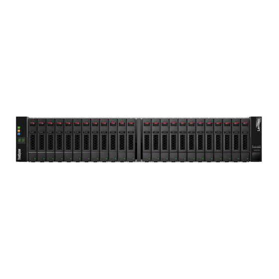
Page 23: 2U24 Enclosure System - Isometric Front Orientation
The 2U12 controller enclosure above is equipped with dual-controllers (4-port FC/iSCSI model shown). NOTE: Please refer to “Enclosure variants” (page 25) for details about various enclosure options. Figure 7 2U24 enclosure system – isometric front orientation Figure 8 2U24 enclosure system – isometric rear orientation Supercapacitor pack... -
Page 24: 5U84 Enclosure System - Isometric Front And Rear Orientations
The 2U24 controller enclosure above is equipped with dual-controllers (4-port SAS model shown). Isometric front view orientation Isometric rear view orientation (EBOD is equipped with dual-IOMS) Figure 9 5U84 enclosure system – isometric front and rear orientations System overview... -
Page 25: Enclosure Variants
Enclosure variants The 2U chassis can be configured as a controller enclosure (DS6200, DS4200, or DS2200) or an expansion enclosure (DS EXP) as shown in Table 3 Table 4. The 5U chassis can be configured as a expansion enclosure (DS EXP) as shown in Table IMPORTANT: The 2U and 5U core products–including key components and CRUs–are described herein. -
Page 26: 2U Enclosure Core Product
IMPORTANT: DS Series and DS EXP/D3284 storage enclosures support dual-controller configuration only. If a partner controller fails, the storage system will fail over and run on a single controller module until the redundancy is restored. For RBODs and EBODs, an IOM must be installed in each IOM slot to ensure sufficient air flow through the enclosure during operation. -
Page 27: 2U Enclosure Rear Panel
2U enclosure rear panel Numeric designators on PCMs and alphabetic designators on IOMs indicate slot sequencing for modules used in 2U enclosures. PCM and IOM modules are available as CRUs. The DS6200 and DS4200 RBODs use 4-port controller modules, whereas the DS2200 RBODs use 2-port controller modules. The DS Series RBODs support the DS EXP EBODs for optionally adding storage. -
Page 28: Port Fc/Iscsi Controller Module Detail (Ds6200/Ds4200)
2U rear panel components Controller modules The top slot for holding IOMs is A and the bottom slot is B. The face plate details of the IOMs show the modules aligned for use in A. This orientation also applies to canister insertion into IOM slots located on the 5U84 enclosure rear panel. -
Page 29: Expansion Module Detail (Ds Exp And D3284)
Serial Ports (Service Only) Figure 20 2-port HD mini-SAS controller module detail (DS2200 only) Expansion module Figure 21 shows the IOM used in supported DS Series expansion enclosures for adding storage. Ports A/B/C ship configured with 12Gb/s HD mini-SAS (SFF-8644) external connectors. Within 2U enclosures, the top slot for holding IOMs is A and the bottom slot is B. -
Page 30: 2U Enclosure Chassis
Power cooling module Figure 22 shows the power cooling module (PCM) used in controller enclosures and optional expansion enclosures. The example shows a PCM oriented for use in the left PCM slot of the enclosure rear panel. Figure 22 Power cooling module (PCM) detail 2U enclosure chassis The 2U chassis consists of a sheet metal enclosure with an integrated midplane PCB and module runner system. -
Page 31: U12 Enclosure Chassis - Isometric Front Orientation
Figure 23 2U12 enclosure chassis – isometric front orientation Figure 24 2U24 enclosure chassis – isometric front orientation NOTE: Either 2U chassis can be configured as a controller enclosure or as an optional expansion enclosure for adding storage. 2U enclosure chassis... -
Page 32: 5U Enclosure Core Product
5U enclosure core product The 5U chassis consists of a sheet metal enclosure, integrated PCBs, and a module runner system. The design concept is based on an enclosure subsystem together with a set of plug-in modules. A typical enclosure system—as supplied—includes the following: •... -
Page 33: 5U Enclosure Front Panel
5U enclosure front panel Figure 25 5U84 enclosure system – front panel components Plan view of a drawer – showing installed DDICs and numeric indexing Forward 0/42 14/56 28/70 1/43 15/57 29/71 2/44 16/58 30/72 3/45 17/59 31/73 4/46 18/60 32/74 5/47 19/61... -
Page 34: 5U Enclosure Rear Panel
IMPORTANT: Drawer sideplanes—also known as side cards—can be hot-swapped as field-replaceable units (FRUs). However, these FRUs require a special tool, and replacement should be performed by qualified service personnel. For additional information, contact support.lenovo.com, select Product support and navigate to Storage Products. -
Page 35: 5U Enclosure Chassis
The 2U enclosures use a redundant PCM that integrates a power supply and cooling fan within the same CRU module, as shown in Figure 22 (page 30). Conversely, the 5U enclosures use separate CRU modules for power supply and cooling/circulation, respectively. Figure 28 shows the power supply module, which provides the enclosure with power connection and a power switch. -
Page 36: Operator's (Ops) Panel
Opening a drawer does not interrupt the functioning of the storage system, and DDICs can be hot-swapped while the enclosure is in operation. However, drawers must not be left open for longer than 2 minutes, or airflow and cooling will be compromised. IMPORTANT: During normal operation, drawers should be closed to ensure proper airflow and cooling within the enclosure. -
Page 37: Enclosure Ops Panel
Identity Ops panel functions (see left ear on front panel) System Power On/Standby LED (Green/Amber) Module Fault LED (Amber) Identity LED (Blue) (power on (5s) test state) Unit Identification LED display Thermal sensor (located behind panel) Figure 31 LEDs: Ops panel – 2U enclosure front panel System Power On/Standby LED (green/amber) LED displays amber when only standby power is available. -
Page 38: Leds: Ops Panel - 5U Enclosure Front Panel
provides the functions shown in the illustration below and listed in the table. See also “Ops panel LEDs” (page 100). Ops panel functions (see left ear on front panel) Unit Identification LED display System Power On/Standby LED (Green/Amber) Module Fault LED (Amber) Logical Status (Amber) Top Drawer Fault (Amber) Bottom Drawer Fault (Amber) -
Page 39: Power Cooling Module - 2U Enclosures
Power cooling module – 2U enclosures AC-DC power is provided by up to two auto-ranging Power Cooling Modules (PCMs) with integrated axial cooling fans. The IOMs control fan speed. Also see “System airflow” (page 40) for optimal cooling within the enclosure(s). -
Page 40: System Airflow
PCMs are hot-pluggable, and replacement should only take a few seconds to do. Replacement must be completed as soon as possible after the removal of the defective PCM to avoid a thermal exception. The replacement procedure should be completed within an absolute maximum of 2 minutes. IMPORTANT: Operation of the enclosure with any modules missing will disrupt the airflow, and the disks will not receive sufficient cooling. - Page 41 Dual PSUs provide redundant power for the 5U system: if one PSU fails, the other keeps the system running while you replace the faulty module. PSUs are hot-swappable. Replacement of a PSU can be performed while the enclosure is running, but the procedure must be completed within two minutes of the removal of the defective module.
-
Page 42: Fan Cooling Module - 5U Enclosures
Fan cooling module – 5U enclosures The five fan cooling modules (FCMs) at the rear of the enclosure maintain all system components below their maximum temperature, assuming the ambient temperature is below 35ºC. Fan speed within the FCMs is governed by the controller modules. -
Page 43: Controller And Expansion Modules
Controller and expansion modules This section describes the IOMs used in Lenovo ThinkSystem DS Series storage enclosures. They are mechanically and electrically compliant to the latest SBB v2.1 specification. The isometric rear orientation in Figure 36 shows a frontal face plate view of a 4-port FC/iSCSI controller module aligned for use in the top controller module slot located on the 2U enclosure rear panel. - Page 44 = iSCSI (2) = FC (1) Description Definition Host 4/8/16Gb FC Off — No link detected. Link Status/ Green — The port is connected and the link is up. Link Activity Blinking green — The link has I/O activity. Host 10GbE iSCSI Off —...
-
Page 45: Leds:ds6200/Ds4200 Fc/Iscsi Controller Modules (Fc And 10Gbe Sfps)
4-When the port is down, both LEDs are off. Figure 37 LEDs:DS6200/DS4200 FC/iSCSI controller modules (FC and 10GbE SFPs) = iSCSI (2) = FC (1) Description Definition Not used in example The FC SFP is not shown in this example. Host 1Gb iSCSI Off —... -
Page 46: Leds: Ds6200/Ds4200 Iscsi Controller Module (1Gb Rj-45 Sfps)
4-When port is down, both LEDs are off. Figure 38 LEDs: DS6200/DS4200 iSCSI controller module (1Gb RJ-45 SFPs) 1 = HD mini-SAS host ports Description Definition Host 12Gb SAS Green — The port is connected and the link is up. Link Status/ Amber —... - Page 47 = FC (1) = iSCSI (2) Description Definition Host 4/8/16Gb FC Off — No link detected. Link Status/ Green — The port is connected and the link is up. Link Activity Blinking green — The link has I/O activity. Host 10GbE iSCSI Off —...
-
Page 48: Leds: Ds2200 Fc/Iscsi Controller Modules (Fc Or 10Gbe Sfps)
4-When port is down, both LEDs are off. Figure 40 LEDs: DS2200 FC/iSCSI controller modules (FC or 10GbE SFPs) = FC (1) = iSCSI (2) Description Definition Not used in example The FC SFP is not shown in this example. Host 1Gb iSCSI Off —... -
Page 49: Leds: Ds2200 Iscsi Controller Module (1Gb Rj-45 Sfps)
2-When in 1GbE iSCSI mode, the SFPs must be a qualified 1GbE iSCSI optic option. 3-When powering up and booting, iSCSI LEDs will be on/blinking momentarily, then they will switch to the mode of operation. 4-When port is down, both LEDs are off. Figure 41 LEDs: DS2200 iSCSI controller module (1Gb RJ-45 SFPs) 1 = HD mini-SAS host ports Description... -
Page 50: Controller Failure When A Single-Controller Is Operational
4-When port is down, both LEDs are off. Figure 42 LEDs: DS2200 SAS controller module (HD mini-SAS) NOTE: When a Link Status LED is lit, it remains so, even if the controller is shut down via the SMC or the CLI. When a controller is shut down or otherwise rendered inactive—its Link Status LED remains illuminated—... -
Page 51: Leds: Rear Panel "Cache Status
is being maintained by the supercapacitor, the Cache Status LED blinks at a rate of 1/10 second on and 9/10 second off. If the controller has failed or does not start, is the Cache Status LED on/blinking? Answer Action No, the Cache LED status is off, and the If the problem persists, replace the controller module. -
Page 52: 12Gb/S Expansion Module Leds
12Gb/s expansion module LEDs If optional expansion enclosures have been cabled to add storage, the supported DS Series expansion enclosures are configured with dual expansion modules. Description Definition Green — The expansion module is operating normally. Blinking green — System is booting. Off —... -
Page 53: Disk Drive Module
IMPORTANT: RBOD/EBOD configurations: • When the expansion module shown above (Figure 43) is used with DS Series controller modules for adding storage, its middle HD mini-SAS expansion port (“B”) is disabled by the firmware. See also Figure 55 (page 68) •... -
Page 54: Dual Path Lff 3.5" Disk Drive Carrier Modules
NOTE: Isometric pictorial views of supported drive carriers are provided in the following illustrations. Modules are shown oriented for insertion into disk drive slots located on the enclosure front panel. 3.5" SAS drive Figure 44 Dual path LFF 3.5" disk drive carrier modules Figure 45 Dual path SFF 2.5"... -
Page 55: Drive Status Indicators
Figure 46 2.5" to 3.5" hybrid drive carrier adapter Drive status indicators Green and amber LEDs on the front of each drive carrier module indicate disk drive status. The SEP controls these LEDs. “Disk drive carrier module LEDs” (page 97) describes the LED states. -
Page 56: Ddic In 5U Chassis
DDIC in 5U chassis Each disk drive is housed in a carrier that enables secure insertion of the disk drive into the drawer with the appropriate SAS carrier transition card. Figure 48 shows a DDIC with a 3.5" disk and Figure 49 shows a DDIC with an adapter and a 2.5"... - Page 57 The DDIC features a latch button (center of top view) and a slide latch with arrow label (left of latch button). These features allow you to install and secure the DDIC into the disk slot within the drawer. They also allow you to disengage the DDIC from its slot, and remove it from the drawer. The DDIC features a single Drive Fault LED (top view on right), which illuminates amber when the disk has a fault.
-
Page 58: Enclosure Management
• Figure 49 (page 56) for the DDIC holding the 2.5" disk with 3.5" adapter Figure 50 Pictorial view of 5U84 drawer fully populated with DDICs Enclosure management SBB IOMs actively manage the enclosure. Each module has a SAS expander with its own storage enclosure processor (SEP) that provides a SES target for a host to interface to through the ANSI SES Standard. -
Page 59: Installation
Installation Installation checklist This chapter shows how to plan for and successfully install your enclosure system into an industry standard 19-inch rack cabinet. Test File. CAUTION: To install the system, use only the power cords supplied, or power cables that match the specification quoted in “AC power cords”... -
Page 60: Planning For Installation
3-The Storage Management Console is introduced in “Accessing the SMC” (page 94). See the Storage Manager Guide or online help for additional information. Planning for installation Before beginning the enclosure installation, familiarize yourself with the system configuration requirements. The figures listed below show the locations for each plug-in module: •... -
Page 61: Preparing The Site And Host Server
• A 5U enclosure—delivered without DDICs installed—requires four people to lift it from the box. A suitable mechanical lift is required to hoist the enclosure for positioning in the rack. Make sure you wear an effective anti-static wrist or ankle strap and obey conventional ESD precautions when touching modules and components. -
Page 62: Unpacking The 2U12 And 2U24 Enclosures
2. The unpacking sequence pertaining to 2U enclosures is shown in Figure Figure 51 Unpacking the 2U12 and 2U24 enclosures 2U enclosures are supplied with the midplane PCB and all plug-in modules installed. For information about plug-in module replacement, see Module removal and replacement. -
Page 63: Required Tools
The railkit and accessories box is located immediately below the box lid in the illustration above. CAUTION: With four persons—positioned one at each corner of the enclosure—grip the straps securely by the loops, and lift the enclosure our of the box, using appropriate lifting technique. Place the enclosure in a static-protected area. -
Page 64: Installing The 5U Enclosure
e. Repeat the above sequence of steps for the companion rail. Figure 53 Securing brackets to the rail (left hand rail shown for 2U) 3. Install the enclosure into the rack: a. Lift the enclosure and align it with the installed rack rails, taking care to ensure that the enclosure remains level. -
Page 65: Securing The Brackets To The Rail (Left Hand Rail Shown For 5U)
3. Locate the rail location pins inside the front of the rack, and extend the length of the rail assembly to enable the rear location pins to locate. Ensure the pins are fully located in the square or round holes in the rack posts. See also Figure Figure 54 Securing the brackets to the rail (left hand rail shown for 5U) -
Page 66: Fde Considerations
Reinsert all of the rear panel modules, and install all of the DDICs into the drawers accessed from the front panel per the following instructions: • Installing a fan cooling module “Installing an FCM” (page 142) • Installing a PSU “Installing a PSU”... -
Page 67: Cable Requirements For Expansion Enclosures
Cable requirements for expansion enclosures When adding storage, use only Lenovo ThinkSystem or OEM-qualified cables, and observe the following guidelines: •... -
Page 68: Cabling Connections Between A 2U Controller Enclosure And 2U Expansion Enclosures
Controller A Controller A Controller B Controller B Add enclosures up to maximum (10) Add enclosures up to maximum (10) Reverse cabling Straight-through cabling Figure 55 Cabling connections between a 2U controller enclosure and 2U expansion enclosures The diagram above (left) shows reverse cabling of a DS Series dual-controller 2U enclosure and supported DS EXP 2U drive enclosures configured with dual expansion modules. - Page 69 for DS EXP, and on the following page for DS Series controller enclosures cabled with D3284 expansion enclosures. Connecting the controller enclosure and optional expansion enclosures...
-
Page 70: Cabling Connections Between A 2U Controller Enclosure And D3284 Expansion Enclosure-Reverse
Controller A Controller B Reverse cabling Figure 56 Cabling connections between a 2U controller enclosure and D3284 expansion enclosure–reverse Figure 56 Figure 57 show maximum configuration cabling for a DS6200/DS4200 controller enclosure with D3284 expansion enclosures. and the IMPORTANT entry beneath that figure. Refer to these diagrams NOTE: See also Figure 21 (page 29) when cabling D3284 expansion enclosures together with DS6200/DS4200 controller enclosures. -
Page 71: Power Cord Connection
Power cord connection Connect a power cord from each PCM or PSU on the enclosure rear panel to the PDU (power distribution unit) as shown in the illustrations below. Controller Enclosure Power Distribution Units (AC UPS shown) Figure 58 Typical AC power cord connection from PDU to PCM (2U) Expansion Enclosure Power Distribution Units (AC UPS shown) Figure 59 Typical AC power cord connection from PDU to PSU (D3284) -
Page 72: Grounding Checks
“Connecting a management host on the network” (page 79). The FC and iSCSI product models can be licensed to support replication, whereas the HD mini-SAS models cannot. Use only Lenovo ThinkSystem or OEM-qualified cables for host connection: • Qualified Fibre Channel SFP and cable options •... -
Page 73: Cnc Technology
ULP can show all LUNs through all host ports on both controllers, and the interconnect information is managed by the controller firmware. ULP appears to the host as an active-active storage system, allowing the host to select any available path to access the LUN, regardless of disk group ownership. TIP: See the topic about configuring system settings in the Storage Management Guide to initially configure the system or change system configuration settings (such as configuring host ports). - Page 74 whereas each DS2200 10GbE iSCSI controller module provides two host ports. CNC ports are designed for use with a 10GbE iSCSI SFP supporting data rates up to 10Gb/s, using either one-way or mutual CHAP (Challenge-Handshake Authentication Protocol). Installation...
-
Page 75: Hd Mini-Sas
The 10GbE iSCSI ports are used in either of two capacities: • To connect two storage systems through a switch for use of replication. • For attachment to 10GbE iSCSI hosts directly, or through a switch used for the 10GbE iSCSI traffic. The first usage option requires valid licensing for the replication feature, whereas the second option requires that the host computer supports Ethernet, iSCSI, and optionally, multipath I/O. -
Page 76: Host Connection
Host connection DS6200/DS4200 controller enclosures support up to eight direct-connect server connections, four per controller module. DS2200 controller enclosures support up to four server connections, two per controller module. Connect appropriate cables from the server’s HBAs to the controller module’s host ports as described below, and shown in the following illustrations. -
Page 77: Connecting Hosts: Ds6200/Ds4200 Direct Attach - One Server/ One Hba/ Dual Path
NOTE: In the examples that follow, a single diagram represents CNC and SAS host connections for DS6200 and DS4200 respectively. The location and sizes of the host ports are very similar. A single diagram represents CNC and SAS host connections for DS2200. Blue cables show controller A paths and green cables show controller B paths for host connection. -
Page 78: Connecting Hosts: Ds6200/Ds4200 Direct Attach - Four Servers/ One Hba Per Server/ Dual Path
DS6200/DS4200 Server 2 Server 1 Server 3 Server 4 Figure 64 Connecting hosts: DS6200/DS4200 direct attach – four servers/ one HBA per server/ dual path Switch attach A switch attach solution—or SAN—places a switch between the servers and the controller enclosures within the storage system. -
Page 79: Connecting A Management Host On The Network
DS6200/DS4200 Server 2 Server 1 Server 3 Server 4 Figure 67 Connecting hosts: DS6200/DS4200 switch attach – four servers/ multiple switches/ SAN fabric Connecting a management host on the network The management host directly manages storage systems over an Ethernet network. 1. -
Page 80: New User Setup
New user setup This product does not provide default users. When you first connect to the system, you will be prompted to set up a new user with manage capability. NOTE: At start up, the CLI (Serial/SSH) and WBI (HTTPS) are the only interfaces through which the system can be configured until the new user is created. -
Page 81: Setting Network Port Ip Addresses Using The Cli Port And Cable
Setting network port IP addresses using the CLI port and cable If you did not use DHCP to set network port IP values, set them manually as described below. • You can use the generic mini-USB cable and the USB CLI port. If you plan on using a mini-USB cable, you will need to enable the port for communication using DB9 serial cable. -
Page 82: Terminal Emulator Display Settings
Within the illustration below, the IOM is aligned for use in the bottom (0B) controller module slot in a 2U enclosure. Figure 68 Connecting a USB cable to the CLI port 4. If using a mini-USB cable, enable the CLI port for subsequent communication. Linux customers should enter the command syntax provided in “Setting parameters for the device driver”... - Page 83 7. Press Enter to display the CLI prompt (#). The CLI displays the system version, Management Controller version, and login prompt. NOTE: Follow the new user setup process to create the first user on the system. See “New user setup” (page 80) for details.
-
Page 84: Configure Controller Network Ports
NOTE: Using HyperTerminal with the CLI on a Microsoft Windows host: On a host computer connected to a controller module’s mini-USB CLI port, incorrect command syntax in a HyperTerminal session can cause the CLI to hang. To avoid this problem, use correct syntax, use a different terminal emulator, or connect to the CLI using telnet rather than the mini-USB cable. -
Page 85: Set Ipv4 Values For Network Ports
For IPv6, when Manual mode is enabled you can enter up to four static IP addresses for each controller. When Auto is enabled, the following initial values are set and remain set until the system is able to contact a DHCPv6 and/or SLAAC server for new addresses: •... -
Page 86: Change The Cnc Port Mode
NOTE: The following IP addresses are reserved for internal use by the storage system: 169.254.255.1, 169.254.255.2, 169.254.255.3, 169.254.255.4, and 127.0.0.1. Because these addresses are routable, do not use them anywhere in your network. 6. Perform one of the following: To save your settings and continue configuring your system, click Apply. ... - Page 87 be connected to the primary system. If the primary system goes offline, a connected server can access the replicated data from the secondary system. Replication configuration possibilities are many, and can be cabled—in switch attach fashion—to support the CNC-based systems (SAS systems do not support replication) on the same network, or on different networks. Connecting two storage systems to replicate volumes...
- Page 88 As you consider the physical connections of your system—specifically connections for replication—keep several important points in mind: • Ensure that controllers have connectivity between systems, whether the destination system is co-located or remotely located. • Qualified Converged Network Controller options can be used for host I/O or replication, or both. •...
-
Page 89: Cabling For Replication
Cabling for replication This section shows example replication configurations for CNC-based controller enclosures. NOTE: Simplified versions of controller enclosures are used in cabling illustrations to show CNC host ports used for I/O or replication, given that only the external connectors used in the host interface ports differ. •... -
Page 90: Connecting Two Ds6200/Ds4200 Storage Systems For Replication: Multiple Servers/Switches/One Location
Figure 71 Figure 72 (page 90) show I/O and replication occurring on different physical networks. For optimal protection, use three switches. Connect one (DS2200) or two (DS6200/DS4200) ports from each controller module to the left switch. Connect one (DS2200) or two (DS6200/DS4200) ports from each controller module to the right switch. -
Page 91: Connecting Two Ds2200 Storage Systems For Replication: Multiple Servers/Switches/Two Locations
DS2200 controller enclosure DS2200 controller enclosure I/O switch I/O switch Ethernet To host servers To host servers (site A) (site B) Figure 74 Connecting two DS2200 storage systems for replication: multiple servers/switches/two locations Figure 73 (page 90) Figure 74 represent two branch offices cabled to enable disaster recovery and backup. In case of failure at either the local site or the remote site, you can fail over the application to the available site. -
Page 92: Operation
Operation Before you begin Before powering on the enclosure system, make sure that all modules are firmly seated in their correct slots. Verify that you have successfully completed the sequential “Installation Checklist” instructions in Table 9 (page 59). Once you have completed steps 1 through 11, you can access the management interfaces using your web-browser to complete the system setup. -
Page 93: Operator's (Ops) Panel Leds
NOTE: Guidelines for consideration when powering enclosures on and off • Remove the AC power cord before inserting or removing a PCM (2U) or PSU (5U). • Move the PCM or PSU power switch to the off position before connecting or disconnecting the AC power cord. •... -
Page 94: Accessing The Smc
described in “Replacing a DDIC” (page 134), while adhering to guidelines provided in “Populating drawers” (page 137). Accessing the SMC Upon completing the hardware installation, you can access the controller module’s web-based management interface—Storage Management Console (SMC)—to configure, monitor, and manage the storage system. Invoke your web browser and enter the IP address of the controller module’s network port in the address field, then press Enter. -
Page 95: Troubleshooting And Problem Solving
They are not intended to be used as troubleshooting procedures for configured systems using production data and I/O. NOTE: For additional information, navigate to support.lenovo.com. In the All Products field, search for your ThinkSystem product by typing the name (e.g., DS6200). -
Page 96: 2U Enclosure Leds
2U enclosure LEDs 580W PCM LEDs Under normal conditions, the PCM OK LEDs will be a constant green. See also Figure 33 (page 39). When a fault occurs, the colors of the LEDs will display as shown in the following table. Table 13 PCM LED states PCM OK Fan Fail... -
Page 97: Disk Drive Carrier Module Leds
• If the above actions do not resolve the fault, contact Lenovo for assistance. Disk drive carrier module LEDs Disk drive status is monitored by a green LED and an amber LED mounted on the front of each drive carrier... -
Page 98: Iom Leds
Disk Activity LED Disk Fault LED Status/condition* (Green) (Amber) Off (disk module/enclosure) Not present Blink off with activity Blinking: 1s on/1s off Identify 1 down: Blink with Drive link (PHY lane) down activity 2 down: Off Fault (leftover/failed/locked-out) Blink off with activity Available Blink off with activity Storage system: Initializing... -
Page 99: 5U Enclosure Leds
If the restart does not resolve the fault, remove the IOM and reinsert it. • If the above actions do not resolve the fault, contact Lenovo for assistance. IOM replacement may be necessary. Expansion module LEDs Expansion IOM status is monitored by the LEDs located on the face plate. See also Figure 16 (page 27). -
Page 100: Psu Leds
PSU LEDs Figure 28 (page 34) for a visual description of the Power Supply Unit (PSU) module faceplate. Table 17 PSU LED states CRU Fail AC Missing Power (Amber) (Amber) (Green) Status No AC power to either PSU. PSU present, but not supplying power or PSU alert state. (usually due to critical temperature) Mains AC present, switch on. -
Page 101: Drawer Leds
Drawer LEDs Figure 30 (page 36) for a visual description of the Drawer LED inserts located on each drawer bezel. Table 20 Drawer LED descriptions Status/description Sideplane OK/ Green if the sideplane card is working and there are no power problems. Power Good Drawer Fault Amber if a drawer component has failed. -
Page 102: Ddic Led
DDIC LED The DDIC supports LFF 3.5" and SFF 2.5" disks as shown in Figure 48 (page 56) Figure 49 (page 56). The illustration below shows the top panel of the DDIC as viewed when the disk is aligned for insertion into the drawer slot. -
Page 103: Troubleshooting 2U Enclosures
Troubleshooting 2U enclosures The following sections describe common problems that can occur with your enclosure system, and some possible solutions. For all of the problems listed in Table 21, the module fault LED on the Ops panel will light amber to indicate a fault. -
Page 104: Thermal Monitoring And Control
Thermal monitoring and control The storage enclosure system uses extensive thermal monitoring and takes a number of actions to ensure component temperatures are kept low, and to also minimize acoustic noise. Air flow is from the front to back of the enclosure. -
Page 105: Troubleshooting 5U Enclosures
Troubleshooting 5U enclosures The table describes common problems that can occur with your enclosure system, together with possible solutions. For all of the problems listed in Table 22, the Module Fault LED on the Ops panel will light amber to indicate a fault. - Page 106 As noted in “Accessing the SMC” (page 94), use the Storage Management Console to configure and provision the system upon completing the hardware installation. As part of this process, configure and enable event notification so the system will notify you when a problem occurs that is at or above the configured severity (see the Configuring event notification topic within the Storage Manager Guide).
-
Page 107: Basic Steps
Basic steps • Gather fault information, including using system LEDs as described in “Gather fault information” (page 108). • Determine where in the system the fault is occurring as described in “Determine where the fault is occurring” (page 108). • Review event logs as described in “Review the event logs”... -
Page 108: Performing Basic Steps
Performing basic steps You can use any of the available options described above in performing the basic steps comprising the fault isolation methodology. Gather fault information When a fault occurs, it is important to gather as much information as possible. Doing so will help you determine the correct action needed to remedy the fault. -
Page 109: If The Enclosure Does Not Initialize
If the enclosure does not initialize It may take up to two minutes for all enclosures to initialize. If an enclosure does not initialize: • Perform a rescan • Power cycle the system • Make sure the power cord is properly connected, and check the power source to which it is connected •... -
Page 110: Isolating A Host-Side Connection Fault
Isolating a host-side connection fault For additional information, navigate to support.lenovo.com. In the All Products field, search for your ThinkSystem product by typing the name (e.g., DS6200). Host-side connection troubleshooting featuring CNC ports For additional information, navigate to support.lenovo.com. In the All Products field, search for your ThinkSystem product by typing the name (e.g., DS6200). -
Page 111: Customer-Replaceable Units
Customer-replaceable units NOTE: The following tables share the table endnotes located beneath them. See Figure 77 (page 115) pictorial views of IOM CRUs used in the different Lenovo ThinkSystem enclosures. Table 23 DS6200 enclosure models Lenovo ThinkSystem DS6200: 4-port controller enclosure matrix 2.5"... -
Page 112: Crus Addressing 2U 12-Drive Chassis
Figure 77 (page 115) shows isometric pictorial representations of controller modules and expansion modules used in 2U 12-drive Lenovo ThinkSystem enclosures. Modules are shown oriented for insertion into IOM slot A located on the enclosure rear panel. Troubleshooting and problem solving... -
Page 113: Crus Addressing 2U 24-Drive Chassis
CRUs addressing 2U 24-drive chassis NOTE: The 2U24 chassis is configurable as either an RBOD (DS6200/DS4200/DS2200) or an EBOD (DS EXP). Table 27 DS6200/DS4200/DS2200/DS EXP product components for 2U 24-drive chassis Item Enclosure component description Disk drive (SFF) a) 2.5" disk drive module (disks of differing type/speed and storage capacity: SAS, SSD) b) Dummy drive carrier module (blank to maintain optimum air flow within enclosure) Ear components (not customer replaceable) a) Left ear assembly... -
Page 114: Crus Addressing High-Density 5U 84-Drive Chassis
Figure 77 (page 115) shows isometric pictorial representations of controller modules and expansion modules used in 2U 24-drive Lenovo ThinkSystem enclosures. Modules are shown oriented for insertion into IOM slot A located on the enclosure rear panel. CRUs addressing high-density 5U 84-drive chassis NOTE: The 5U84 chassis is configured as an EBOD (D3284) for use with DS6200/DS4200 controllers. -
Page 115: Sbb Ioms Used In Ds Series Storage Enclosures
4-port SAS controller module 4-port FC/iSCSI controller module 3-port expansion module 2-port SAS controller module 2-port FC/iSCSI controller module Figure 77 SBB IOMs used in DS Series storage enclosures Customer-replaceable units... -
Page 116: Module Removal And Replacement
Module removal and replacement Overview This chapter provides procedures for replacing CRUs (customer-replaceable units), including precautions, removal instructions, installation instructions, and verification of successful installation. Each procedure addresses a specific task. Certain procedures refer to related documentation. See “Related documentation” (page 14) for a list of these documents and where to find them online. -
Page 117: Cru Replacement For 2U Chassis
If you do not have any of the suggested equipment for proper grounding, have an authorized technician install the part. For more information about static electricity or assistance with product installation, contact support.lenovo.com, select Product Support and navigate to Storage Products. CRU replacement for 2U chassis NOTE: Unless noted otherwise within a passage pertaining to a particular CRU, the replacement procedure should be completed within two minutes of the removal of the defective module. - Page 118 TIP: This step is not required for hot-swapping. However, it is required when replacing both PCMs at once. 3. Switch off the faulty PCM, and disconnect the power supply cable. 4. If replacing a single PCM via hot-swap, proceed to step 5.
- Page 119 9. If replacing two PCMs, repeat steps 5 through 8, being mindful of the illustrations TIP on page 117. Replacing a power cooling module...
-
Page 120: Installing A Pcm
Installing a PCM Refer to Figure 78 (page 118) Figure 79 (page 118) when performing this procedure, but ignore the directional arrows—since you will insert the module into the slot—rather than extracting it. IMPORTANT: Handle the PCM carefully, and avoid damaging the connector pins. Do not install the PCM if any pins appear to be bent. -
Page 121: Removing A Lff Drive Carrier Module
Removing a LFF drive carrier module 1. Press the latch in the carrier handle towards the handle hinge to release the carrier handle as shown below. Figure 80 Removing a LFF disk drive module (1 of 2) 2. Gently move the drive carrier module approximately 25 mm (1-inch), then wait 30 seconds. Figure 81 Removing a LFF disk drive module (2 of 2) 3. -
Page 122: Installing A Lff Drive Carrier Module
Installing a LFF drive carrier module 1. Release the drive carrier handle by depressing the latch in the handle. Figure 82 LFF drive carrier module in open position 2. Insert the drive carrier module into the enclosure. Make sure that the drive carrier is positioned such that the top of the disk is facing up, and the handle opens from the left as you face the enclosure front panel. -
Page 123: Removing A Sff Drive Carrier Module
4. Cam the drive carrier home. The camming foot on the carrier will engage into a slot in the enclosure. Continue to push firmly until the handle fully engages. You should hear a click as the latch handle engages and holds the handle closed. -
Page 124: Removing A Sff Disk Drive Module (1 Of 2)
1. Press the latch in the carrier handle downward to release the carrier handle so that it can revolve outward as shown below. Figure 85 Removing a SFF disk drive module (1 of 2) 2. Gently move the drive carrier module outward from the drive slot. Figure 86 Removing a SFF disk drive module (2 of 2) 3. -
Page 125: Installing A Sff Drive Carrier Module
Installing a SFF drive carrier module 1. Release the carrier handle by pressing the latch in the handle downwards, and opening the hinged handle as shown in Figure 87 (page 125). Insert the carrier into the enclosure in a vertical position. IMPORTANT: Make sure the carrier is positioned such that the disk is on its left side and the handle opens from the top. -
Page 126: Installing A Sff Drive Carrier Module (1 Of 2)
2. Slide the carrier fully into the enclosure until it is stopped by the camming lever on the bottom of the carrier. Figure 88 Installing a SFF drive carrier module (1 of 2) 3. Cam the carrier home. The camming lever on the carrier will engage into the a slot in the enclosure. Continue to push firmly until the handle fully engages. -
Page 127: Replacing A Dummy Drive Carrier
Replacing a dummy drive carrier A dummy drive carrier module is removed from the 2U enclosure simply by pulling the module out of the drive slot. A dummy drive carrier module is installed in the enclosure by properly aligning it and inserting it into the drive slot, followed by pushing it securely into place. -
Page 128: Configuring Partner Firmware Update
3. Check the system status and event logs to verify that the system is stable. 4. Replace the partner controller as described in these instructions. Configuring partner firmware update In a dual-controller system in which PFU is enabled, when you update firmware on one controller, the system automatically updates the partner controller. -
Page 129: Shutting Down A Controller Module
2. Run the show disk-group-statistics command a second time. This provides you a specific window of time (the interval between requesting the statistics) to determine if data is being written to or read from the disk group. Record the numbers displayed. 3. -
Page 130: Removing An Iom
The Display LED on the Ops panel located on the enclosure left ear will be blinking green when the above command is invoked. NOTE: See the CLI Reference Guide for additional information. Removing an IOM IMPORTANT: Considerations for removing controller modules: •... -
Page 131: Installing An Iom
6. Grip the latch handle and ease the IOM forward from the slot as shown in Figure 4-port FC/iSCSI controller module shown Figure 91 Removing an IOM NOTE: The illustration above shows a 4-port controller module of model type FC/iSCSI. However, the procedure applies to all IOMs discussed herein. -
Page 132: Verifying Component Operation
4. Set the module in position by manually closing the latch. You should hear a click as the latch handle engages and secures the IOM to its connector on the back of the midplane. 5. Reconnect the cables. NOTE: In a dual-controller system in which PFU is enabled, when you update the firmware on one controller, the system automatically updates the partner controller. -
Page 133: Cru Replacement For 5U Chassis
CRU replacement for 5U chassis NOTE: Unless noted otherwise within a passage pertaining to a particular CRU, the replacement procedure should be completed within two minutes of the removal of the defective module. Accessing drawers To observe or replace a DDIC, you must open the drawer in which it resides. The top drawer (Drawer 0) and the bottom drawer (Drawer 1) are accessed from the enclosure front panel. -
Page 134: Closing A Drawer
3. Pull the drawer outward until it locks at the drawer stops as shown in Figure 94 (page 134). This drawer has been fully populated with DDICs. Figure 94 Opening a drawer (2 of 2) IMPORTANT: The drawer must not remain open for more than two minutes while the enclosure is powered on. Closing a drawer 1. -
Page 135: Removing A Ddic (1 Of 2)
If the drive number is known, use the information contained in Figure 26 (page 33), which provides a single plan view of a drawer that is dual-indexed with top drawer (left integer) and bottom drawer (right integer) slot numbering. If the disk has failed, a fault LED is lit on the front panel of the affected drawer. - Page 136 5. Pull the DDIC upwards and out of the drawer slot. Figure 96 Removing a DDIC (2 of 2) Module removal and replacement...
-
Page 137: Installing A Ddic
Installing a DDIC IMPORTANT: Failed disks must be replaced with approved disks. Contact your service provider for details. 1. Open the relevant drawer per the instructions provided in “Opening a drawer” (page 133). 2. Align the DDIC with the target disk slot as shown in Figure 95 (page 135) and insert it into the disk slot. -
Page 138: Installation Guidelines
Installation guidelines The recommended order for partially populating drives in the 5U84 enclosure optimizes the airflow through the chassis. Please reference the following illustrations: • Figure 25 (page 33) shows location and indexing of drawers accessed from the enclosure front panel. •... - Page 139 4. If replacing a single PSU via hot-swap proceed to step 5. If replacing both PSUs, verify that the enclosure was shut down using management interfaces, and that the enclosure is powered off. 6. Verify that the power cord is disconnected. 7.
-
Page 140: Installing A Psu
8. If replacing both PSUs, repeat step 5 through step IMPORTANT: The PSU slot must not be empty for more than 2 minutes while the enclosure is powered. Installing a PSU 1. Ensure that the PSU is switched off. If replacing both PSUs, the enclosure must be powered off via an orderly shutdown using the management interfaces. -
Page 141: Removing An Fcm (1 Of 2)
Illustration needed–LOF item No.28 Figure 100 Removing an FCM (1 of 2) Illustration needed–LOF item No.29 Figure 101 Removing an FCM (2 of 2) Replacing an FCM... -
Page 142: Installing An Fcm
IMPORTANT: The FCM slot must not be empty for more than 2 minutes while the enclosure is powered. Installing an FCM 1. You can hotswap the replacement of a single FCM; however, if replacing multiple FCMs, the enclosure must be powered off via an orderly shutdown using the management interfaces. -
Page 143: Iom Latch Operation Detail
Illustrations in the expansion module removal procedure show rear panel views of the enclosure, and IOMs are properly aligned for insertion into the IOM slots. 1. Locate the enclosure containing the expansion canister you wish to replace. 2. Disconnect any cables connected to the IOM. Label each cable to facilitate re-connection to the replacement IOM. -
Page 144: Installing An Iom
Figure 104 Removing an IOM (2 of 2) Installing an IOM See CAUTION bullets regarding electrostatic discharge and anti-static protection on page 116. CAUTION: If passive copper cables are connected, the cable must not have a connection to a common ground/earth point. - Page 145 5. Reconnect the cables. 6. See “Verifying component operation” (page 132). Replacing an IOM...
-
Page 146: A Technical Specifications
Technical specifications Enclosure dimensions Table 29 2U enclosure dimensions Specification Metric Imperial units units Overall enclosure height (2U) 87.9 mm 3.46 in Width across mounting flange (located on front of chassis) 483 mm 19.01 in Width across body of enclosure 443 mm 17.44 in Depth from face of mounting flange to back of enclosure body... -
Page 147: Environmental Requirements
3-Weights may vary due to different power supplies, IOMs, and differing calibrations between scales. 4-Weights may vary due to actual number and type of disk drives (SAS or SSD) and air management modules installed. Environmental requirements Table 32 Ambient temperature and humidity Specification Temperature range Relative humidity... -
Page 148: Power Cooling Module
Power cooling module Specifications for the HE580W PCM are provided in the table. Table 33 2U Power cooling module specifications Specification Measurement/description Dimensions (size) 84.3 mm high x 104.5 mm wide x 340.8 mm long: • X-axis length: 104.5 mm (4.11 in) •... - Page 149 Table 34 5U84 Power supply unit specifications Specification Measurement/description Holdup time 5 ms from ACOKn high to rails out of regulation (see SBB v2 specification) Hot pluggable Mains inlet connector IEC60320 C20 with cable retention Weight 3 kg (6.6 lb) Cooling fans Separate fan cooling module CRU provides 2 adjacent fans: 80x80x38mm Power supply unit...
-
Page 150: B Standards And Regulations
Standards and regulations International standards The enclosure system complies with the requirements of the following agencies and standards: • CE to EN 60950-1 • CB report to IEC 60950-1 • UL & cUL to UL 60950-1 second edition Potential for radio frequency interference USA Federal Communications Commission (FCC) Notice This equipment has been tested and found to comply with the limits for a class A digital device, pursuant to Part 15... -
Page 151: Ac Power Cords
Please contact your supplier/Lenovo for a copy of the Recycling Procedures applicable to your country. IMPORTANT: Observe all applicable safety precautions detailed in the preceding chapters (weight restrictions, handling batteries and lasers, etc.) when dismantling and disposing of this equipment. -
Page 152: Taiwan Bsmi Rohs Declaration
Taiwan BSMI RoHS declaration Standards and regulations... -
Page 153: Cusb Device Connection
USB device connection Rear panel USB ports Lenovo ThinkSystem DS Series controllers contain a USB (Universal Serial Bus) Device interface pertaining to the Management Controller (MC). The Device interface is accessed via a port on the controller module face plate. -
Page 154: Supported Host Applications
Microsoft Windows operating systems provide a USB serial port driver. However, the USB driver requires details for connecting to DS Series controller enclosures. Lenovo provides a device driver for use in the Windows environment. The USB device driver and installation instructions are available via a download. -
Page 155: Using The Cli Port And Cable-Known Issues On Windows
Although Linux operating systems do not require installation of a device driver, certain parameters must be provided during driver loading to enable recognition of the DS Series controller enclosures. Setting parameters for the device driver 1. Enter the following command: modprobe usbserial vendor=0x210c product=0xa4a7 use_acm=1 2. -
Page 156: Dsfp Option For Cnc Ports
SFP option for CNC ports Locate the SFP transceivers Locate the qualified SFP options for your FC/iSCSI controller canister within your product ship kit. The SFP transceiver (SFP) should look similar to the generic SFP shown in the figure below and in Figure 107 (page 157). -
Page 157: Verify Component Operation
Canister face plate Target CNC port Installed SFP (actuator closed) Align SFP for installation (plug removed/actuator open) Fiber-optic interface cable Figure 107 Install a qualified SFP option into an DS2200 FC/iSCSI controller module Verify component operation View the CNC port Link Status/Link Activity LED on the controller canister face plate. A green LED indicates that the port is connected and the link is up: •... -
Page 158: Index
Index Numerics disk modules carrier blank 55 2U12 DDIC with 2.5" disk and adapter 56 12-drive enclosure (3.5" disks) 12 DDIC with 3.5" disk 56 2U24 dual path LFF 54 24-drive enclosure (2.5" disks) 12 dual path SFF 54 SFF to LFF adapter 55 document accessing conventions and symbols 15... - Page 159 2-port 1Gb iSCSI IOM (CNC) 49 USB device connection 2-port FC IOM (CNC) 48 Command-line Interface (CLI) 153 2-port HD mini-SAS IOM 50 supported host applications 154 3-port expansion module 52 vendor and product ID codes 154 4-port 10GbE iSCSI IOM (CNC) 45 4-port FC IOM (CNC) 45 4-port HD mini-SAS IOM 46 FCM 35...