
Related Manuals for Lenovo Storage D1212


Summary of Contents for Lenovo Storage D1212
- Page 1 Lenovo Storage D1212/D1224/D3284 Hardware Installation and Maintenance Guide Machine Types: 4587 and 6413...
- Page 2 Fourth Edition (February 2018) © Copyright Lenovo 2016, 2018. LIMITED AND RESTRICTED RIGHTS NOTICE: If data or software is delivered pursuant to a General Services Administration “GSA” contract, use, reproduction, or disclosure is subject to restrictions set forth in Contract No. GS-...
-
Page 3: Table Of Contents
Disk Drive LEDs (2U Enclosures) ..580W PCM LEDs ... . Disk Drive LEDs (5U Enclosures) ..© Copyright Lenovo 2016, 2018... - Page 4 ....126 Inserting a PSU ... . . Replacing ESMs ....Lenovo Storage D1212/D1224/D3284Hardware Installation and Maintenance Guide...
- Page 5 Index ....131 Japanese electromagnetic compatibility statements ....127 © Copyright Lenovo 2016, 2018...
- Page 6 Lenovo Storage D1212/D1224/D3284Hardware Installation and Maintenance Guide...
-
Page 7: About This Guide
About this Guide This guide provides information about initial hardware setup, removal, and installation of customer- replaceable units (CRUs) for the Lenovo Storage D1212/D1224/D3284 enclosures. Intended audience This guide is intended for system administrators and storage administrators. Qualified Personnel The personnel referred to within this document are defined as follows: •... -
Page 8: Safety Statements
Safety Information document. For example, if a caution statement is labeled Statement 1, translations for that caution statement are in the Safety Information document under Statement 1. Lenovo Storage D1212/D1224/D3284Hardware Installation and Maintenance Guide... - Page 9 If your system has a module containing a lithium battery, replace it only with the same module type made by the same manufacturer. The battery contains lithium and can explode if not properly used, handled, or disposed of. Do not: © Copyright Lenovo 2016, 2018...
- Page 10 Class 1 Laser Product Laser Klasse 1 Laser Klass 1 Luokan 1 Laserlaite Appareil A Laser de Classe 1 Statement 4 Three graphic illustrations for safety practices when lifting. viii Lenovo Storage D1212/D1224/D3284Hardware Installation and Maintenance Guide...
- Page 11 Statement 7 CAUTION: If the device has doors, be sure to remove or secure the doors before moving or lifting the device to avoid personal injury. The doors will not support the weight of the device. © Copyright Lenovo 2016, 2018...
- Page 12 Do not place any object weighing more than 82 kg (180 lb) on top of rack-mounted devices. >82 kg (180 lb) Statement 11 CAUTION: The following label indicates sharp edges, corners, or joints nearby. Lenovo Storage D1212/D1224/D3284Hardware Installation and Maintenance Guide...
- Page 13 Hazardous voltage, current, and energy levels might be present. Only a qualified service technician is authorized to remove the covers where the following label is attached. Statement 15 CAUTION: Make sure that the rack is secured properly to avoid tipping when the server unit is extended. © Copyright Lenovo 2016, 2018...
- Page 14 The power-control button on the device does not turn off the electrical current supplied to the device. The device also might have more than one connection to dc power. To remove all electrical current Lenovo Storage D1212/D1224/D3284Hardware Installation and Maintenance Guide...
- Page 15 3 meters in length. • Torque the wiring-terminal screws to 12 inch-pounds (1.4 newton-meters). • Incorporate a readily available approved and rated disconnect device in the field wiring. Statement 23 xiii © Copyright Lenovo 2016, 2018...
- Page 16 • Incorporate a readily available approved and rated disconnect device in the field wiring. Statement 25 CAUTION: This product contains a Class 1M laser. Do not view directly with optical instruments. Statement 26 CAUTION: Do not place any object on top of rack-mounted devices. Lenovo Storage D1212/D1224/D3284Hardware Installation and Maintenance Guide...
- Page 17 • The dc supply source shall be located within the same premises as this equipment. • Switching or disconnecting devices shall not be in the earthed circuit conductor between the dc source and the point of connection of the earthing electrode conductor. © Copyright Lenovo 2016, 2018...
- Page 18 The device also might have more than one power cord. To remove all electrical current from the device, ensure that all power cords are disconnected from the power source. Lenovo Storage D1212/D1224/D3284Hardware Installation and Maintenance Guide...
- Page 19 This device is for use only with Listed CONREF_to_boilerplate_terms. Attention: This product is suitable for use on an IT power distribution system whose maximum phase-to phase-voltage is 240 V under any distribution fault condition. xvii © Copyright Lenovo 2016, 2018...
- Page 20 Lenovo Storage D1212/D1224/D3284Hardware Installation and Maintenance Guide...
-
Page 21: Chapter 1. Safety Guidelines
It is ESSENTIAL that all apertures hold drives before the enclosure system is used. Empty drive bays must hold dummy drive carrier modules. Figure 1. Module Bay Caution Label (1) © Copyright Lenovo 2016, 2018... -
Page 22: 2U Enclosures Only
In a rack containing more than one enclosure, do not open more than one drawer per rack at a time. CAUTION: Lenovo Storage D1212/D1224/D3284Hardware Installation and Maintenance Guide... -
Page 23: Electrical Safety
Operating temperatures inside the enclosure drawers can reach up to 60°C. Take care when opening drawers and removing drive carriers. Figure 4. Hot Surface Warning Label CAUTION: Due to product acoustics, it is recommended that users wear ear protection for any prolonged exposure. -
Page 24: 2U Enclosures Only
When addressing these concerns consideration should be given to the electrical power consumption rating shown on the nameplate. Lenovo Storage D1212/D1224/D3284Hardware Installation and Maintenance Guide... -
Page 25: 2U Enclosures Only
• The electrical distribution system must provide a reliable earth connection for each enclosure and the rack. • The rack, when configured with the enclosures, must meet the safety requirements of UL 60950-1 and IEC 60950-1. 2U Enclosures Only Always remove all PCMs to minimize weight, before loading the enclosure into a rack. Each PCM in each enclosure has an earth leakage current of 1.0 mA. - Page 26 Lenovo Storage D1212/D1224/D3284Hardware Installation and Maintenance Guide...
-
Page 27: Chapter 2. System Overview
• “Enclosure Management” on page 31 Enclosure Introduction You can connect Storage D1212/D1224/D3284 enclosures directly to the host. You also can optionally connect Storage D3284 enclosure to a Lenovo Storage DS-series as the expansion enclosure. For more information about the operation of Storage DS-series, refer to ThinkSystem DS6200/DS4200/DS2200/DS EXP Storage Manager Guide. - Page 28 Figure 8. 2U12 Enclosure System – front view Figure 9. 2U12 Enclosure System – rear view Lenovo Storage D1212/D1224/D3284Hardware Installation and Maintenance Guide...
- Page 29 Figure 10. 2U24 Enclosure System – front view Figure 11. 2U24 Enclosure System – rear view Chapter 2 System Overview...
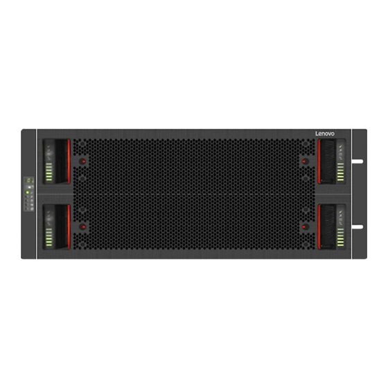
- Page 30 Figure 12. 5U84 Enclosure System – front view Lenovo Storage D1212/D1224/D3284Hardware Installation and Maintenance Guide...
-
Page 31: Enclosure Variants
Figure 13. 5U84 Enclosure System – rear view Enclosure Variants The following enclosure configurations are possible. 2U12 12 x LFF (Large Form Factor) and 12 x HFF (Hybrid Form Factor) drives. Table 1. 2U12 Enclosure Variants Product Configuration PCMs ESMs D1212 12 Gb/s direct dock LFF SAS 2U24... -
Page 32: The 2U Enclosure Core Product
Important: To ensure correct airflow and cooling, all PSU bays and cooling module bays must contain a functioning unit. If the enclosure is run with a single ESM, the other ESM bay must be filled with a blank module. Figure 14. Module Locations (2U12) Lenovo Storage D1212/D1224/D3284Hardware Installation and Maintenance Guide... -
Page 33: Enclosure Chassis
Figure 15. Module Locations (2U24) Enclosure Chassis The chassis (Figure 16 “Enclosure Chassis (2U12) ” on page 14) consists of a sheet metal enclosure assembly with an integrated midplane PCB and module runner system. • The chassis has a 19 inch rack mounting that enables it to be installed on to standard 19 inch racks and uses two EIA units of rack space (3.5 inch) for a 2U enclosure. -
Page 34: The 5U Enclosure Core Product
The 5U Enclosure Core Product The OneStor design concept is based on an enclosure subsystem together with a set of plug-in modules. A typical enclosure system (as supplied) comprises: • An enclosure chassis comprising: Lenovo Storage D1212/D1224/D3284Hardware Installation and Maintenance Guide... - Page 35 – Two sliding drawers containing Disk Drive In Carrier (DDIC) modules. – An operator’s (Ops) panel. – A front bezel. – A midplane PCB into which other components connect. – Four sideplanes and six baseplanes for front end components connectivity. •...
-
Page 36: Enclosure Chassis
Each drawer can be locked shut by turning both anti-tamper locks clockwise using a screwdriver with a Torx T20 bit (see Figure 18 “Module Locations” on page 15). Each side of each drawer has a series of status LEDs, shown in the following figure.. Lenovo Storage D1212/D1224/D3284Hardware Installation and Maintenance Guide... -
Page 37: Operator's (Ops) Panel (2U Enclosures)
Figure 20. Drawer LEDs Important: During normal operation, drawers must be kept shut to ensure correct airflow and cooling. Operator’s (Ops) Panel (2U Enclosures) The enclosure front panel has an operator’s (Ops) panel (shown in Figure 21 “Enclosure Front Operator’s Panel ”... -
Page 38: System Power On/Standby Led (Green/Amber)
Use a VPD (Vital Product Data) option to configure the unit identification display. The display will be on by default, and display a value of 0. See section. Lenovo Storage D1212/D1224/D3284Hardware Installation and Maintenance Guide... -
Page 39: Thermal Sensor
Thermal Sensor This thermal sensor is located outside the enclosure and sends input to the enclosure about its external operating ambient temperature. Operator’s (Ops) Panel (5U Enclosures) The front of the enclosure features an operator’s (ops) panel (shown in Figure 22 “Enclosure Operator’s Panel ”... -
Page 40: Unit Identification Display
• In normal operation the green LED is on and flickers as the drive operates. • In normal operation the amber LED state is: – Off if there is no drive present. – Off as the drive operates. – On if there is a drive fault. Lenovo Storage D1212/D1224/D3284Hardware Installation and Maintenance Guide... -
Page 41: Disk Drive Leds (5U Enclosures)
Disk Drive LEDs (5U Enclosures) LEDs in each drive carrier module are shown in Figure 62 “Drive Fault LED” on page 61. • In normal operation the amber LED state is: – Off as the drive operates. – On if there is a drive fault. Power Cooling Modules (PCM) Note: 2U Enclosures only. -
Page 42: Multiple Pcms
Note: 5U Enclosures only. Power is provided by two 2214W PSUs, as shown in Figure 25 “2214W PSU” on page 23. It requires an input of 200VAC to 240VAC at 50 Hz to 60 Hz. Lenovo Storage D1212/D1224/D3284Hardware Installation and Maintenance Guide... -
Page 43: Cooling Module
Figure 25. 2214W PSU Dual PSUs provide redundant power for the system: if one PSU fails, the other keeps the system running while you replace the faulty module. The PSUs are hot-swappable. Replacement of a PSU can be performed while the enclosure is running, but the procedure must be completed within two minutes of the removal of the defective PSU. -
Page 44: System Airflow
Important: The environment in which the enclosure operates must be dust-free to ensure adequate airflow. Environmental Service Module (ESM) This user guide describes the 12Gb/s JBOD ESMs. The ESMs are mechanically and electrically compliant to the latest SBB V2.1 specification. Lenovo Storage D1212/D1224/D3284Hardware Installation and Maintenance Guide... - Page 45 Figure 28. 12 Gb/s SAS JBOD Module (2U Enclosures) Figure 29. 12 Gb/s SAS JBOD Module (5U Enclosures) Each ESM maintains VPD in EEPROM devices, and is interconnected by SBB defined I C buses on the midplane. In this way, the SBB modules can discover the type and capabilities of the partner SBB modules and vice versa within the enclosure.
-
Page 46: 12 Gb/S Jbod Module Leds
Figure 30. 12 Gb/s SAS JBOD Module Connectors and Indicators (2U enclosures) (viewed from rear of enclosure) Figure 31. 12 Gb/s SAS JBOD Module Connectors and Indicators (5U enclosures) (viewed from rear of enclosure) Lenovo Storage D1212/D1224/D3284Hardware Installation and Maintenance Guide... -
Page 47: Drive Carrier Module (2U Enclosures)
Table 8. Ethernet connector LEDs Link/Activity LED (Left) State No Link Link Blinking Activity Table 9. Ethernet connector LEDs Speed LED (Right) State 10-Base-T 100-Base-TX SAS Connections The ESM has three mini-SAS-HD (SFF-8644) connector receptacles. By default each is configured as an SAS-3 universal port. - Page 48 Figure 33. 2.5" Drive Carrier Module with no Interposer Card Note: For information about the LEDs of 2.5" drive carrier module, refer to Figure 57 “2.5" Drive Carrier LEDs ” on page 55 Lenovo Storage D1212/D1224/D3284Hardware Installation and Maintenance Guide...
-
Page 49: Drive Status Indicators
Figure 34. 2.5" to 3.5" Cabrio Drive Carrier Adapter Note: For information about the LEDs of 3.5" drive carrier module, refer to Figure 56 “3.5" Drive Carrier LEDs ” on page 54 Drive Status Indicators Green and amber LEDs on the front of each drive carrier module indicate disk drive status; shown in Figure 35 “Dummy Drive Carrier Module ”... -
Page 50: Disk Drives In Carriers (Ddics) (5U Enclosures)
Note: When mixing SSDs and HDDs in the top front row (slot 0 - slot 13), up to four SSDs can be installed in the first four slots (slot 0 - slot 3). • HDDs in the same row must have the same rotational speed. Lenovo Storage D1212/D1224/D3284Hardware Installation and Maintenance Guide... -
Page 51: Enclosure Management
Figure 36. A Disk Drive In Carrier (DDIC) The 2.5" SAS solid-state drive with 3.5" adapter is supported. The drive carrier has a single amber LED which is lit when the drive has a fault. Enclosure Management SBB ESMs actively manage the enclosure. Each module has a SAS expander with its own storage enclosure processor (SEP) that provides a SES target for a host to interface to through the ANSI SES Standard. - Page 52 Lenovo Storage D1212/D1224/D3284Hardware Installation and Maintenance Guide...
-
Page 53: Chapter 3. Installation
2U enclosures only. Two PCMs provide full power redundancy – this lets the system continue to operate while a faulty PCM is replaced. Power Supply Units (PSUs) 5U enclosures only. Power is provided by two 2214W PSUs. © Copyright Lenovo 2016, 2018... -
Page 54: Prepare For Enclosure Installation
• A standard AC power supply from an independent source or a rack power distribution unit with an UPS (uninterruptible power supply). • A host computer with the correct software, BIOS, and drives. Before make a call to Lenovo phone service, check the correct software and hardware configurations at http://support.lenovo.com... - Page 55 Figure 37. Unpacking the 2U12 and 2U24 Enclosure Systems Chapter 3 Installation...
-
Page 56: How To Plan And Configure Your Installation
• Minimum depth: 933 mm (36.73 inches) from rack posts to maximum extremity of enclosure (excludes rear cabling). • Weight: up to 50 kg (110 lb), dependent upon configuration, per enclosure. • The rack should cause a maximum back pressure of 5 pascals (0.5 mm water gauge). Lenovo Storage D1212/D1224/D3284Hardware Installation and Maintenance Guide... -
Page 57: Rack Mounting Rail Kit
Rack Mounting Rail Kit Various sets of rack mounting rails are available for use in 19 inch rack cabinets. These rails have been designed and tested for the maximum enclosure weight and to make sure that multiple enclosures may be installed without loss of space within the rack. -
Page 58: 5U84 Enclosures
Ensure that the pins are fully located in the square or round holes in the rack posts (see Figure 40 “Mounting the System into a Rack (left-hand rail only shown for clarity)” on page 39). Lenovo Storage D1212/D1224/D3284Hardware Installation and Maintenance Guide... - Page 59 Figure 40. Mounting the System into a Rack (left-hand rail only shown for clarity) 4. Fully tighten all clamping screws and middle slide locking screws. 5. Ensure the rear spacer clips (x4) are fitted tight to the edge of the rack post. 6.
-
Page 60: Module Installation
Important: When more than one PSU is fitted, connect each PSU to separate and independent supplies to guarantee redundancy. Figure 42. Typical AC Power Cable Connections to PCMs Lenovo Storage D1212/D1224/D3284Hardware Installation and Maintenance Guide... -
Page 61: Grounding Checks
• MiniSAS HD to MiniSAS HD cable or MiniSAS HD to MiniSAS cable • Power cord • Rack kit If you connect the enclosure to a Lenovo Storage DS-series as the expansion enclosure, ensure that you have the following items: • Lenovo Storage DS-series •... - Page 62 • One or more non-RAID adapter (HBA) in the host can access the drives in the JBOD ESMs. Clustering is supported in this condition. See Figure 45 “Single host with dual host adapters- Multiple 2U Enclosures” on page 43. Figure 44. Single host with single host adapter- Multiple 2U Enclosures Lenovo Storage D1212/D1224/D3284Hardware Installation and Maintenance Guide...
- Page 63 Figure 45. Single host with dual host adapters- Multiple 2U Enclosures Multiple enclosures may be connected together using SAS patch cables, up to a maximum of 192 SFF/96 LFF drives or 8 enclosures. An example configuration is shown as below. Figure 46.
- Page 64 • One or more non-RAID adapter (HBA) in the host can access the drives in the JBOD ESMs. Clustering is supported in this condition. See Figure 49 “Single host with dual host adapters- Multiple 5U Enclosures” on page 45 and Figure 50 “Dual Host – Multiple 12G 5U Enclosures” on page 46. Lenovo Storage D1212/D1224/D3284Hardware Installation and Maintenance Guide...
- Page 65 Figure 48. Single host with single host adapter- Multiple 5U Enclosures Figure 49. Single host with dual host adapters- Multiple 5U Enclosures Multiple enclosures may be connected together using SAS patch cables, up to a maximum of 336 DDICs or 4 enclosures.
- Page 66 Multiple enclosures may be connected together using SAS patch cables, up to a maximum of two 5U enclosures and two 2U12 enclosures, a maximum of two 5U enclosures and one 2U24 enclosures or a maximum of 192 drives. An example configuration is shown as below. Lenovo Storage D1212/D1224/D3284Hardware Installation and Maintenance Guide...
- Page 67 Figure 51. Dual Host – Mixed 12G 2U and 5U Enclosures Note: When two servers are connected, the dual host must be supported by application. Multiple enclosures may be connected together using SAS patch cables, up to a maximum of two 5U enclosures and two 2U12 enclosures, a maximum of two 5U enclosures and one 2U24 enclosures or a maximum of 192 drives.
- Page 68 Multiple enclosures may be connected together using SAS patch cables, up to a maximum of two 5U enclosures and two 2U12 enclosures, a maximum of two 5U enclosures and one 2U24 enclosures or a maximum of 192 drives. An example configuration is shown as below. Lenovo Storage D1212/D1224/D3284Hardware Installation and Maintenance Guide...
- Page 69 Figure 53. Dual Host – Mixed 12G 2U and 5U Enclosures Note: When two servers are connected, the dual host must be supported by application. Figure 54. Single host – multiple 5U enclosure as expansion enclosures for Storage DS-series Chapter 3 Installation...
- Page 70 Lenovo Storage D1212/D1224/D3284Hardware Installation and Maintenance Guide...
-
Page 71: Chapter 4. Operation
The Unit Identification Display has the electrical capability of driving all seven of the segments, plus the dot/ decimal point in each character of the display. How To Set the Unit Identification Number Note: 5U enclosures only. © Copyright Lenovo 2016, 2018... -
Page 72: Power Down
PCMs or moving the PSU switch to the "Off" position. For PCM, see “Power Cooling Modules (PCM)” on page 21. For PSU, see “Power Supply Unit (PSU)” on page 22. Lenovo Storage D1212/D1224/D3284Hardware Installation and Maintenance Guide... -
Page 73: Chapter 5. Troubleshooting And Problem Solving
• “Field Replaceable Units (5U Enclosures)” on page 74 Initial Start-Up Problems Faulty Cords First check that you have wired up the enclosure system correctly. Contact Lenovo service or representative for replacements if: • Cords are missing or damaged. • Plugs are incorrect. -
Page 74: 580W Pcm Leds
• In normal operation the amber LED state is: – Off if there is no drive present. – Off as the drive operates. – On if there is a drive fault. Figure 56. 3.5" Drive Carrier LEDs Lenovo Storage D1212/D1224/D3284Hardware Installation and Maintenance Guide... -
Page 75: Operator's Panel Leds (2U Enclosures)
Figure 57. 2.5" Drive Carrier LEDs Table 12. Drive LED States Green Drive LED Amber Drive LED Status No drive installed On/Flashing Drive installed and operational Flashing: 1 second on / 1 second off SES device identity set SES device fault bit set Power control circuit failure Flashing: 1 second on / 1 second off RAID array status... -
Page 76: Operator's Panel Leds (5U Enclosures)
Enclosure identification or invalid ID selected Operator’s Panel LEDs (5U Enclosures) The operator’s (ops) panel (see Figure 58 “Ops Panel LEDs ” on page 57) displays the aggregated status of all the modules. Lenovo Storage D1212/D1224/D3284Hardware Installation and Maintenance Guide... -
Page 77: Psu Leds
Figure 58. Ops Panel LEDs Table 14. Ops Panel LED Descriptions Display/LED Description Unit Identification Display Usually shows the identification number for the enclosure, but can be used for other purposes. Power On/Standby LED Amber if the system is in standby. Green if the system has full power. Module Fault LED Amber indicates a fault in a PSU, cooling module or ESM. -
Page 78: Cooling Module Leds
AC power missing, PSU in standby (other PSU is providing power). GEM software has lost communication with the PSU. – PSU has failed. Follow the procedure in “Removing a PSU” on page 91. Cooling Module LEDs Note: 5U enclosures only. Lenovo Storage D1212/D1224/D3284Hardware Installation and Maintenance Guide... -
Page 79: Drawer Leds
Figure 60. Cooling Module LEDs Table 16. Cooling Module LED Descriptions Description Module OK Constant green indicates that the fan is working correctly. Off means the fan has failed. Follow the procedure in “Replacing a Cooling Module” on page 89. Fan Fault Amber indicates that a fan has failed. -
Page 80: Disk Drive In Carrier (Ddic) Led
Each disk drive has a single amber drive fault LED as shown in Figure 62 “Drive Fault LED” on page 61. When lit, this indicates a drive failure – the drive should be replaced as soon as possible using the procedure described in “Replacing a Disk Drive in Carrier (DDIC)” on page 86. Lenovo Storage D1212/D1224/D3284Hardware Installation and Maintenance Guide... -
Page 81: Esm Leds
Figure 62. Drive Fault LED ESM LEDs ESM LED are shown as below. Figure 63. 12Gb/s SAS JBOD Module Connectors and Indicators (2U enclosures) (viewed from rear of enclosure) Chapter 5 Troubleshooting and Problem Solving... -
Page 82: Temperature Sensors
PCM alert - loss of DC power from a single PCM PCM fan fall Fault - loss of redundancy Module Fault ESM detected PCM fault Fault Module Fault PCM removed Configuration error Module Fault Lenovo Storage D1212/D1224/D3284Hardware Installation and Maintenance Guide... -
Page 83: Power Cooling Module Faults
Table 19. Alarm Conditions (continued) Status Severity OPs Panel LED Fault - critical Module Fault Enclosure configuration error (VPD) Low warning temperature alert Warning Module Fault High warning temperature alert Warning Module Fault Over-temperature alarm Fault - critical Module Fault C bus failure Fault - loss of redundancy Module Fault... -
Page 84: Thermal Alarm
Cooling module fan failure Fault – loss of redundancy ESM detected PSU fault Fault PSU removed Configuration error Fault – critical Enclosure configuration error (VPD) Low warning temperature alert Warning High warning temperature alert Warning Lenovo Storage D1212/D1224/D3284Hardware Installation and Maintenance Guide... -
Page 85: Thermal Monitoring And Control
Table 20. Alarm Conditions (continued) Status Severity Fault – critical Over-temperature alarm Under-temperature alarm Fault – critical C bus failure Fault – loss of redundancy Ops panel communication error (I Fault – critical RAID error Fault – critical ESM fault Fault –... -
Page 86: Thermal Alarm
Important: In this situation (where PCM or PSU programming has failed) the PCM or PSU can be reprogrammed but it must not be moved between bays. If the PCM or PSU is moved, it must be returned to the original bay before reprogramming can occur. Lenovo Storage D1212/D1224/D3284Hardware Installation and Maintenance Guide... -
Page 87: Ddic Pop-Up Troubleshooting
DDIC Pop-up Troubleshooting If a DDIC pops up, the top drawer cannot be fully opened or closed. To solve the problem, perform the corresponding procedure based on the symptom listed in the following table. Note: You can still fully open or close the bottom drawer even though a DDIC pops up. Action Symptom Cause... - Page 88 Note: After the pop-up DDIC is detected, keep the strip contacting with the side of the pop-up DDIC at an angle of about 30 degrees. Figure 66. Keeping the strip contacting with the pop-up DDIC Lenovo Storage D1212/D1224/D3284Hardware Installation and Maintenance Guide...
- Page 89 4. Move and place the strip between the chassis lid and the pop-up DDIC. Then, rotate the strip directly on the top of the pop-up DDIC and fully open the top drawer at the same time. Figure 67. Moving and placing the strip between the chassis lid and the pop-up DDIC Figure 68.
- Page 90 8. Reach the pop-up DDIC by reaching out a hand behind the top drawer. If you still cannot reach the pop-up DDIC, do the following: a. Remove the front bezel from the right side of the chassis. Lenovo Storage D1212/D1224/D3284Hardware Installation and Maintenance Guide...
- Page 91 b. Insert a flat head screwdriver into the slot nearby the bottom drawer and push the retaining arm up. Figure 70. Pushing the retaining arm up c. Open the bottom drawer until you can reach the pop-up DDIC. CAUTION: When the top and bottom drawers (with drives installed) open at the same time, ensure that the rear of chassis is suitably fastened on the workbench.
-
Page 92: Field Replaceable Units (2U Enclosures)
External MiniSAS HD 8644/MiniSAS HD 8644 2M Cable 00YL855 External MiniSAS HD 8644/MiniSAS HD 8644 3M Cable 01DC163 External MiniSAS HD 8644/2xMiniSAS HD 8644 2M Y-Cable 39M5068 Line cord - 2.8 m, 10A/250V, C13 to IRAM 2073 (Argentina) Lenovo Storage D1212/D1224/D3284Hardware Installation and Maintenance Guide... - Page 93 Table 21. Field Replaceable Units (continued) FRU Part Number Description 39M5076 Line cord - 4.3 m, 10A/125V, C13 to NEMA 5-15P (US) 39M5095 Line cord - 2.8 m, 10A/250V, C13 to NEMA 6-15P (US) 39M5102 Line cord - 2.8 m, 10A/250V, C13 to AS/NZ 3112 (Australia/NZ) 39M5123 2.8 m, 10A/230V, C13 to CEE7-VII (Europe) 39M5130...
-
Page 94: Field Replaceable Units (5U Enclosures)
PWRCRD, 4.3m, US/CAN, NEMA L15-30P - (3P+Gnd) to 3X IEC 320 C19 Line Cord 69Y1614 PWRCRD, 4.3m, EMEA/AP, IEC 309 32A (3P+N+Gnd) to 3X IEC 320 C19 Line Cord 69Y1616 PWRCRD, 4.3m, A/NZ, (PDL/Clipsal) 32A (3P+N+Gnd) to 3X IEC 320 C19 Line Cord Lenovo Storage D1212/D1224/D3284Hardware Installation and Maintenance Guide... -
Page 95: Chapter 6. Module Removal And Replacement
• For 2U enclosures, after replacing any of the following FRUs or CRUs, update the firmware for all of the following FRUs or CRUs to the latest version. To download the latest firmware, go to the Lenovo Support Web site. -
Page 96: Removing A Power Cooling Module
4. Grip the handle and withdraw the PCM, taking care to support the base of the module with both hands, as you remove it from the enclosure. (See Figure 72 “Removing a PCM (2) ” on page 77). Lenovo Storage D1212/D1224/D3284Hardware Installation and Maintenance Guide... -
Page 97: Installing A Power Cooling Module
Figure 72. Removing a PCM (2) Installing a Power Cooling Module Important: Handle the PCM carefully and avoid damaging the connector pins. Do not install the PCM if any pins appear to be bent. 1. Check for damage, especially to all connectors. 2. - Page 98 Figure 73. Removing a Drive Carrier Module (1) 2. Gently remove the drive carrier module approximately 1 inch (25mm), then wait 30 seconds (see Figure 74 “Removing a Drive Carrier Module (2)” on page 79). Lenovo Storage D1212/D1224/D3284Hardware Installation and Maintenance Guide...
-
Page 99: Installing A 3.5-Inch Drive Carrier Module
Figure 74. Removing a Drive Carrier Module (2) 3. Remove the module fully from the drive bay. CAUTION: Dummy drive carrier modules MUST be fitted to ALL unused drive bays. There will be inadequate drive cooling if any are left open. Installing a 3.5-inch Drive Carrier Module To install a 3.5-inch drive carrier module, do the following: 1. - Page 100 4. Cam the drive carrier home. The camming foot on the carrier engages into a bay in the enclosure. Continue to push firmly until the handle fully engages. A click should be heard as the latch engages and holds the handle closed. Lenovo Storage D1212/D1224/D3284Hardware Installation and Maintenance Guide...
-
Page 101: Removing/Replacing 2.5-Inch Drive Carrier Modules
Figure 77. Engaging a Drive Carrier Module in an Enclosure Removing/Replacing 2.5-inch Drive Carrier Modules The removal/replacement procedure for 2.5” drive carrier modules is basically the same as for 3.5” drive carriers, except that the 2.5” drive carriers are mounted vertically. To remove/replace 2.5-inch drive carrier modules, do the following: 1. - Page 102 2. Slide the carrier fully into the enclosure until it is stopped by the camming lever on the bottom of the carrier (see Figure 79 “Installing a 2.5” Drive Carrier Module (1)” on page 82). Figure 79. Installing a 2.5” Drive Carrier Module (1) Lenovo Storage D1212/D1224/D3284Hardware Installation and Maintenance Guide...
- Page 103 3. Cam the carrier home. The camming lever on the carrier will engage into a bay in the enclosure. Continue to push firmly until the handle fully engages. A click should be heard as the latch engages and holds the handle closed (see Figure 80 “Installing a 2.5” Drive Carrier Module (2)” on page 83). Important: Make sure that the handle always opens from the top.
-
Page 104: Dummy Carrier Module Removal/Replacement
(see Figure 83 “Anti-tamper Locks (shown disengaged)” on page 84). Unlock them if necessary by rotating them counterclockwise using a screwdriver with a torx T20 bit. Figure 83. Anti-tamper Locks (shown disengaged) Lenovo Storage D1212/D1224/D3284Hardware Installation and Maintenance Guide... -
Page 105: Closing A Drawer
2. Push the drawer latches inward and hold them. (See Figure 84 “Opening the Bottom Drawer” on page 85 3. Pull out the drawer until it locks open. Figure 84. Opening the Bottom Drawer Important: The drawer must not be left open for more than two minutes while the enclosure is powered. Closing a Drawer Note: 5U enclosures only. -
Page 106: Replacing A Disk Drive In Carrier (Ddic)
4. Slide the release button, as shown in the following figure. 5. Slide the top surface in the direction of the arrow until the latch releases, as shown in the following figure. The DDIC should pop up slightly from the slot. Lenovo Storage D1212/D1224/D3284Hardware Installation and Maintenance Guide... -
Page 107: Inserting A Ddic
Figure 87. Removing a DDIC 6. If the DDIC does not pop up, perform steps 1 and 2 simultaneously in above figure. The DDIC will pop up slightly from the slot. 7. Lift the DDIC out of the slot, as shown in the following figure. Figure 88. - Page 108 4. Check that the release latch has returned to its locked position, as shown in Figure 90 “Latch Position of a Correctly Inserted Drive” on page 88. Figure 90. Latch Position of a Correctly Inserted Drive 5. Close the drawer using the instructions in “Closing a Drawer” on page 85. Lenovo Storage D1212/D1224/D3284Hardware Installation and Maintenance Guide...
-
Page 109: Replacing A Cooling Module
Note: The drawers must be populated with drives in whole rows at a time (there are 3 rows of 14 drives per drawer). The minimum number of drives in an enclosure is 14, the number of rows must not differ by more than 1 between top and bottom drawers and the rows should be populated from the front to the rear of the enclosure. -
Page 110: Inserting A Cooling Module
2. Slide the cooling module into its bay until the latch clicks home. The enclosure automatically detects and makes use of the new unit. Replacing a Power Supply Unit (PSU) Note: 5U enclosures only. This topic provides instructions on how to remove and insert the PSU. Lenovo Storage D1212/D1224/D3284Hardware Installation and Maintenance Guide... -
Page 111: Removing A Psu
Removing a PSU Important: Before removing a PSU, make sure that you have a replacement module to insert. 1. Identify the PSU to be removed using appropriate fault reporting software. 2. As shown in Figure 94 “Removing a PSU Module (1) ” on page 91 and Figure 95 “Removing a PSU Module (2) ”... -
Page 112: Inserting A Psu
• Before removing an ESM, make sure that you have a replacement module to insert. • After installing a new ESM, DHCP is enabled by default. If necessary, configure the static IP address using the JBOD Configure Utility. You can download the utility from the Lenovo Support Web site. Removing an ESM (2U Enclosures) Important: Do not remove this module unless a replacement can be immediately added. -
Page 113: Installing An Esm (2U Enclosures)
Figure 97. Removing an ESM Installing an ESM (2U Enclosures) Note: EMC (Electromagnetic Compatibility) precautions: if passive copper cables are connected, the cable must not have a connection to a common ground/earth point. 1. Examine for damage, closely inspect the interface connector. Do not install it if the pins are bent. 2. -
Page 114: Removing An Esm (5U Enclosures)
95, pinch the latch on the module and pull the handle toward you (1). This will lever the module out of its connector on the midplane. 4. Pull the module out of the enclosure (2). Lenovo Storage D1212/D1224/D3284Hardware Installation and Maintenance Guide... - Page 115 Figure 100. Removing an ESM (1) Figure 101. Removing an ESM (2) Important: The ESM bay must not be empty for more than two minutes while the enclosure is powered. Chapter 6 Module Removal and Replacement...
-
Page 116: Inserting An Esm (5U Enclosures)
4. Close the latch until it clicks home. This levers the module home into its connector on the midplane. The enclosure automatically detects the new unit. 5. Connect the cables to the new module (if necessary, refer to the note you made before you removed the cables from the defective ESM). Lenovo Storage D1212/D1224/D3284Hardware Installation and Maintenance Guide... -
Page 117: Chapter 7. Gem Cli Commands
• The vertical bar (|) is used to mean as a logical OR, meaning that one option or the other can be chosen. Example: help [all] | [] This means that the help command can be invoked with the all parameter or the name of a command: © Copyright Lenovo 2016, 2018... -
Page 118: Connecting To The Gem Cli
The default account and password are: • User name: cliuser • Password: L@12sT12 (case sensitive) Note: After replacing the chassis, the password will be restored to the default value. Reset the password as needed. Lenovo Storage D1212/D1224/D3284Hardware Installation and Maintenance Guide... -
Page 119: Gem Cli General Commands
GEM CLI General Commands The CLI commands in the following section are for general use, and can be issued without any possibility of causing data loss or other serious problems. change_password Changes the password for the currently logged in user. The password is changed at the enclosure level, so all ESMs use the updated login credentials on completion. - Page 120 Device stats: read write success slave arb loss busy error timeout slavedrop no resp total ----------------Retry Stats------------------------ Success after NoRetry OneRetry MultiRetry Failure after MultiRetry Customer VPD Region Total Writes Success Lenovo Storage D1212/D1224/D3284Hardware Installation and Maintenance Guide...
- Page 121 Note: This command is supported on version 5.0.0.19 or later. Syntax: driveinv Example: 2+15:08:09.151 M0 GEM> driveinv Temp Drive Vendor Model Serial Size LENOVO ST1800MM0018 X S3Z0EFWW0000M642K6YY L59B 29 C 1800 GB LENOVO ST1800MM0018 X S3Z0DTJB0000K6436TPH L59B 30 C 1800 GB...
- Page 122 : 0994355-04 Expander 0: Present SMP Target : 50050CC11084913F SSP Target : 50050CC11084913E 0+03:42:29.293 M0 GEM> help Displays the complete list of supported CLI commands or provides usage information for a specified command. Lenovo Storage D1212/D1224/D3284Hardware Installation and Maintenance Guide...
- Page 123 Syntax: help [[type] | [cmd]] type The command classification to list The specific command for which the usage shall be retrieved Example: 0+03:42:33.775 M0 GEM> help Supported commands: change_password To change Current User Password cleardriveindicator Clears the drive indicator LED ddump System-wide diagnostic dump ddumpo...
-
Page 124
The subnet mask to assign to the Ethernet port gateway An optional default route to be used by the Ethernet port • dns
[dns2] Set any static DNS addresses. These settings will only apply if DHC address assignment is disabled. Lenovo Storage D1212/D1224/D3284Hardware Installation and Maintenance Guide... - Page 125 dns1 The IPv4 address of the primary Domain Name Server Dns2 The IPv4 address of the optional secondary Domain Name Server Example: 0+03:56:39.021 M0 GEM> ipconfig Ether: Enabled DHCP: Enabled Telnet: Enabled 10.22.168.220 Net Mask: 255.255.240.0 Gateway: 10.22.160.1 DNS 1: 0.0.0.0 DNS 2: 0.0.0.0...
- Page 126 0+06:55:42.222 M0 GEM> logdumpnv 6+05:03:14.780; ENC_MGT; can_manager; 04; M0:Message 3 6+05:03:12.353; ENC_MGT; can_manager; 04; M0:Message 2 6+05:03:10.093; ENC_MGT; can_manager; 04; M0:Message 1 0+06:55:43.831 M0 GEM> logdumpnv old 6+05:03:10.093; ENC_MGT; can_manager; 04; M0:Message 1 Lenovo Storage D1212/D1224/D3284Hardware Installation and Maintenance Guide...
-
Page 127
6+05:03:12.353; ENC_MGT; can_manager; 04; M0:Message 2 6+05:03:14.780; ENC_MGT; can_manager; 04; M0:Message 3 0+06:58:00.622 M0 GEM> logdumpnv new 2 6+05:03:14.780; ENC_MGT; can_manager; 04; M0:Message 3 6+05:03:12.353; ENC_MGT; can_manager; 04; M0:Message 2 0+06:58:48.320 M0 GEM> poweroffdrive Powers off the drives within the specified bays. Syntax: poweroffdrive
... - Page 128 Table 23. Zoning Modes Zoning Description D1212 D1224 D3284 mode Zoning Port A -> Universal Port A -> Universal Port A -> Universal disabled Port B -> Universal Port B -> Universal Port B -> Universal Lenovo Storage D1212/D1224/D3284Hardware Installation and Maintenance Guide...
- Page 129 Table 23. Zoning Modes (continued) Zoning Description D1212 D1224 D3284 mode Port C -> Universal Port C -> Universal Port C -> Universal Drives Port A -> Drives 0-1, Port A -> Drives 0-11 Port A -> Drives 0-6, 14-20, 28-34, 42-48, partitioned 4-5, 8-9 56-62, 70-76...
- Page 130 0+03:05:17.297 M0 GEM> setcanisterindicator 0 0+07:29:06.202 M0 GEM> setdriveindicator Starts displaying a drive location indication on the specified drive bay. The drive location indication is used to aid in locating a drive bay for servicing. Lenovo Storage D1212/D1224/D3284Hardware Installation and Maintenance Guide...
-
Page 131
Syntax: setdriveindicator
drive The 0-based ID of the drive bay for which the locate indication is to be displayed Example: 0+03:03:11.579 M0 GEM> setdriveindicator 1 0+03:05:17.297 M0 GEM> settime Sets the current log time for the enclosure. Setting the log time on one ESM synchronises it with the partner ESM, if present. - Page 132 PCM 2 VPD structure : 0x03 PCM 1 VPD CRC : 0x6B58AD13 PCM 2 VPD CRC : 0x6B58AD13 : Not present Battery 1 firmware : Not present Battery 2 firmware 0+07:41:26.877 M0 GEM> Lenovo Storage D1212/D1224/D3284Hardware Installation and Maintenance Guide...
-
Page 133: Chapter 8. Technical Specifications
5°C to 35°C -40°C to +70°C Relative Humidity 20% to 80% non- 5% to 100% non- 20% to 80% non- 5% to 100% non- condensing precipitating condensing condensing Max. Wet Bulb 28°C 29°C 28°C 29°C © Copyright Lenovo 2016, 2018... -
Page 134: Power Cooling Module
Voltage Range 100 - 240 VAC rated Frequency 50/60 Hz Voltage Range Selection Auto ranging: 90 - 264 VAC, 47/63Hz Maximum Inrush Current Power Factor Correction ≥95% @ nominal input voltage Harmonics Meets EN61000-3-2 Lenovo Storage D1212/D1224/D3284Hardware Installation and Maintenance Guide... -
Page 135: Power Supply Unit
Output +5 V @: 42A, +12 V:@ 38A, +5 V standby voltage @ 2.7A Operating Temperature 0° to 57°C Hot Pluggable Switches & LEDs AC mains switch and four status indicator LEDs Enclosure Cooling Dual axial cooling fans with variable fan speed control Power Supply Unit Note: 5U enclosures only. - Page 136 Lenovo Storage D1212/D1224/D3284Hardware Installation and Maintenance Guide...
-
Page 137: Chapter 9. Standards And Regulations
Generic Immunity. Safety Compliance System Product Type Approval UL, cUL, CE Safety Compliance UL 60950-1 second edition IEC 60950 EN 60950 EMC Compliance Conducted Emissions Limit Levels CFR47 Part 15B Class A EN55022 Class A © Copyright Lenovo 2016, 2018... -
Page 138: Ac Power Cords
Please contact your supplier/Lenovo for a copy of the Recycling Procedures applicable to your product. Important: Observe all applicable safety precautions detailed in the preceding chapters (weight restrictions, handling batteries and lasers etc.) when dismantling and disposing of this equipment. -
Page 139: Appendix A. Getting Help And Technical Assistance
Before you call, make sure that you have taken these steps to try to solve the problem yourself. If you believe that you require warranty service for your Lenovo product, the service technicians will be able to assist you more efficiently if you prepare before you call. -
Page 140: Using The Documentation
. Then click Servers and search for the storage system. Creating a personalized support web page You can create a personalized support web page by identifying Lenovo products that are of interest to you. To create a personalized support web page, go to http://www.ibm.com/support/ mynotifications . - Page 141 IBM Taiwan product service contact information: IBM Taiwan Corporation 3F, No 7, Song Ren Rd. Taipei, Taiwan Telephone: 0800-016-888 Appendix A. Getting help and technical assistance...
- Page 142 Lenovo Storage D1212/D1224/D3284Hardware Installation and Maintenance Guide...
-
Page 143: Appendix B. Notices
Lenovo representative for information on the products and services currently available in your area. Any reference to a Lenovo product, program, or service is not intended to state or imply that only that Lenovo product, program, or service may be used. Any functionally equivalent product, program, or service that does not infringe any Lenovo intellectual property right may be used instead. -
Page 144: Trademarks
Lenovo encourages owners of information technology (IT) equipment to responsibly recycle their equipment when it is no longer needed. Lenovo offers a variety of programs and services to assist equipment owners in recycling their IT products. For information on recycling Lenovo products, go to: http://www.lenovo.com/... -
Page 145: Particulate Contamination
If Lenovo determines that the levels of particulates or gases in your environment have caused damage to the device, Lenovo may condition provision of repair or replacement of devices or parts on implementation of appropriate remedial measures to mitigate such environmental contamination. -
Page 146: Federal Communications Commission (Fcc) Statement
Properly shielded and grounded cables and connectors must be used in order to meet FCC emission limits. Lenovo is not responsible for any radio or television interference caused by using other than recommended cables and connectors or by unauthorized changes or modifications to this equipment. Unauthorized changes or modifications could void the user's authority to operate the equipment. -
Page 147: Japanese Electromagnetic Compatibility Statements
Verträglichkeit von Geräten), bzw. der EMV EU Richtlinie 2014/30/EU, für Geräte der Klasse A. Dieses Gerät ist berechtigt, in Übereinstimmung mit dem Deutschen EMVG das EG-Konformitätszeichen - CE - zu führen. Verantwortlich für die Konformitätserklärung nach Paragraf 5 des EMVG ist die Lenovo (Deutschland) GmbH, Meitnerstr. 9, D-70563 Stuttgart. -
Page 148: Korea Communications Commission (Kcc) Statement
JEITA harmonics guideline - Japanese Statement of Compliance for Products More than 20A Korea Communications Commission (KCC) statement This is electromagnetic wave compatibility equipment for business (Type A). Sellers and users need to pay attention to it. This is for any areas other than home. Lenovo Storage D1212/D1224/D3284Hardware Installation and Maintenance Guide... -
Page 149: Russia Electromagnetic Interference (Emi) Class A Statement
Russia Electromagnetic Interference (EMI) Class A statement People's Republic of China Class A electronic emission statement Taiwan Class A compliance statement Appendix B. Notices... -
Page 150: Taiwan Bsmi Rohs Declaration
Taiwan BSMI RoHS declaration Lenovo Storage D1212/D1224/D3284Hardware Installation and Maintenance Guide... -
Page 151: Index
Taiwan product service from the World Wide Web telecommunication regulatory statement from World Wide Web telephone numbers sources of trademarks important notices United States FCC Class A notice information center Japanese electromagnetic compatibility statements © Copyright Lenovo 2016, 2018... - Page 152 Lenovo Storage D1212/D1224/D3284Hardware Installation and Maintenance Guide...